US9200200B2 - Phosphor, light emitting device, surface light source device, display device and illumination device - Google Patents
Phosphor, light emitting device, surface light source device, display device and illumination device Download PDFInfo
- Publication number
- US9200200B2 US9200200B2 US14/118,324 US201214118324A US9200200B2 US 9200200 B2 US9200200 B2 US 9200200B2 US 201214118324 A US201214118324 A US 201214118324A US 9200200 B2 US9200200 B2 US 9200200B2
- Authority
- US
- United States
- Prior art keywords
- phosphor
- light emitting
- light
- light source
- emitting device
- Prior art date
- Legal status (The legal status is an assumption and is not a legal conclusion. Google has not performed a legal analysis and makes no representation as to the accuracy of the status listed.)
- Active, expires
Links
Images




Classifications
-
- C—CHEMISTRY; METALLURGY
- C09—DYES; PAINTS; POLISHES; NATURAL RESINS; ADHESIVES; COMPOSITIONS NOT OTHERWISE PROVIDED FOR; APPLICATIONS OF MATERIALS NOT OTHERWISE PROVIDED FOR
- C09K—MATERIALS FOR MISCELLANEOUS APPLICATIONS, NOT PROVIDED FOR ELSEWHERE
- C09K11/00—Luminescent materials, e.g. electroluminescent or chemiluminescent
- C09K11/08—Luminescent materials, e.g. electroluminescent or chemiluminescent containing inorganic luminescent materials
- C09K11/77—Luminescent materials, e.g. electroluminescent or chemiluminescent containing inorganic luminescent materials containing rare earth metals
-
- C—CHEMISTRY; METALLURGY
- C09—DYES; PAINTS; POLISHES; NATURAL RESINS; ADHESIVES; COMPOSITIONS NOT OTHERWISE PROVIDED FOR; APPLICATIONS OF MATERIALS NOT OTHERWISE PROVIDED FOR
- C09K—MATERIALS FOR MISCELLANEOUS APPLICATIONS, NOT PROVIDED FOR ELSEWHERE
- C09K11/00—Luminescent materials, e.g. electroluminescent or chemiluminescent
- C09K11/08—Luminescent materials, e.g. electroluminescent or chemiluminescent containing inorganic luminescent materials
- C09K11/77—Luminescent materials, e.g. electroluminescent or chemiluminescent containing inorganic luminescent materials containing rare earth metals
- C09K11/7783—Luminescent materials, e.g. electroluminescent or chemiluminescent containing inorganic luminescent materials containing rare earth metals containing two or more rare earth metals one of which being europium
-
- C—CHEMISTRY; METALLURGY
- C09—DYES; PAINTS; POLISHES; NATURAL RESINS; ADHESIVES; COMPOSITIONS NOT OTHERWISE PROVIDED FOR; APPLICATIONS OF MATERIALS NOT OTHERWISE PROVIDED FOR
- C09K—MATERIALS FOR MISCELLANEOUS APPLICATIONS, NOT PROVIDED FOR ELSEWHERE
- C09K11/00—Luminescent materials, e.g. electroluminescent or chemiluminescent
- C09K11/08—Luminescent materials, e.g. electroluminescent or chemiluminescent containing inorganic luminescent materials
- C09K11/0883—Arsenides; Nitrides; Phosphides
-
- C—CHEMISTRY; METALLURGY
- C09—DYES; PAINTS; POLISHES; NATURAL RESINS; ADHESIVES; COMPOSITIONS NOT OTHERWISE PROVIDED FOR; APPLICATIONS OF MATERIALS NOT OTHERWISE PROVIDED FOR
- C09K—MATERIALS FOR MISCELLANEOUS APPLICATIONS, NOT PROVIDED FOR ELSEWHERE
- C09K11/00—Luminescent materials, e.g. electroluminescent or chemiluminescent
- C09K11/08—Luminescent materials, e.g. electroluminescent or chemiluminescent containing inorganic luminescent materials
- C09K11/77—Luminescent materials, e.g. electroluminescent or chemiluminescent containing inorganic luminescent materials containing rare earth metals
- C09K11/7728—Luminescent materials, e.g. electroluminescent or chemiluminescent containing inorganic luminescent materials containing rare earth metals containing europium
-
- C—CHEMISTRY; METALLURGY
- C09—DYES; PAINTS; POLISHES; NATURAL RESINS; ADHESIVES; COMPOSITIONS NOT OTHERWISE PROVIDED FOR; APPLICATIONS OF MATERIALS NOT OTHERWISE PROVIDED FOR
- C09K—MATERIALS FOR MISCELLANEOUS APPLICATIONS, NOT PROVIDED FOR ELSEWHERE
- C09K11/00—Luminescent materials, e.g. electroluminescent or chemiluminescent
- C09K11/08—Luminescent materials, e.g. electroluminescent or chemiluminescent containing inorganic luminescent materials
- C09K11/77—Luminescent materials, e.g. electroluminescent or chemiluminescent containing inorganic luminescent materials containing rare earth metals
- C09K11/7728—Luminescent materials, e.g. electroluminescent or chemiluminescent containing inorganic luminescent materials containing rare earth metals containing europium
- C09K11/7734—Aluminates
-
- C—CHEMISTRY; METALLURGY
- C09—DYES; PAINTS; POLISHES; NATURAL RESINS; ADHESIVES; COMPOSITIONS NOT OTHERWISE PROVIDED FOR; APPLICATIONS OF MATERIALS NOT OTHERWISE PROVIDED FOR
- C09K—MATERIALS FOR MISCELLANEOUS APPLICATIONS, NOT PROVIDED FOR ELSEWHERE
- C09K11/00—Luminescent materials, e.g. electroluminescent or chemiluminescent
- C09K11/08—Luminescent materials, e.g. electroluminescent or chemiluminescent containing inorganic luminescent materials
- C09K11/77—Luminescent materials, e.g. electroluminescent or chemiluminescent containing inorganic luminescent materials containing rare earth metals
- C09K11/7728—Luminescent materials, e.g. electroluminescent or chemiluminescent containing inorganic luminescent materials containing rare earth metals containing europium
- C09K11/77348—Silicon Aluminium Nitrides or Silicon Aluminium Oxynitrides
-
- F21V9/16—
-
- G—PHYSICS
- G02—OPTICS
- G02B—OPTICAL ELEMENTS, SYSTEMS OR APPARATUS
- G02B6/00—Light guides; Structural details of arrangements comprising light guides and other optical elements, e.g. couplings
- G02B6/0001—Light guides; Structural details of arrangements comprising light guides and other optical elements, e.g. couplings specially adapted for lighting devices or systems
- G02B6/0011—Light guides; Structural details of arrangements comprising light guides and other optical elements, e.g. couplings specially adapted for lighting devices or systems the light guides being planar or of plate-like form
-
- H01L33/502—
-
- H—ELECTRICITY
- H05—ELECTRIC TECHNIQUES NOT OTHERWISE PROVIDED FOR
- H05B—ELECTRIC HEATING; ELECTRIC LIGHT SOURCES NOT OTHERWISE PROVIDED FOR; CIRCUIT ARRANGEMENTS FOR ELECTRIC LIGHT SOURCES, IN GENERAL
- H05B33/00—Electroluminescent light sources
- H05B33/12—Light sources with substantially two-dimensional [2D] radiating surfaces
- H05B33/14—Light sources with substantially two-dimensional [2D] radiating surfaces characterised by the chemical or physical composition or the arrangement of the electroluminescent material, or by the simultaneous addition of the electroluminescent material in or onto the light source
-
- H—ELECTRICITY
- H10—SEMICONDUCTOR DEVICES; ELECTRIC SOLID-STATE DEVICES NOT OTHERWISE PROVIDED FOR
- H10H—INORGANIC LIGHT-EMITTING SEMICONDUCTOR DEVICES HAVING POTENTIAL BARRIERS
- H10H20/00—Individual inorganic light-emitting semiconductor devices having potential barriers, e.g. light-emitting diodes [LED]
- H10H20/80—Constructional details
-
- H—ELECTRICITY
- H10—SEMICONDUCTOR DEVICES; ELECTRIC SOLID-STATE DEVICES NOT OTHERWISE PROVIDED FOR
- H10H—INORGANIC LIGHT-EMITTING SEMICONDUCTOR DEVICES HAVING POTENTIAL BARRIERS
- H10H20/00—Individual inorganic light-emitting semiconductor devices having potential barriers, e.g. light-emitting diodes [LED]
- H10H20/80—Constructional details
- H10H20/85—Packages
- H10H20/851—Wavelength conversion means
- H10H20/8511—Wavelength conversion means characterised by their material, e.g. binder
- H10H20/8512—Wavelength conversion materials
-
- Y—GENERAL TAGGING OF NEW TECHNOLOGICAL DEVELOPMENTS; GENERAL TAGGING OF CROSS-SECTIONAL TECHNOLOGIES SPANNING OVER SEVERAL SECTIONS OF THE IPC; TECHNICAL SUBJECTS COVERED BY FORMER USPC CROSS-REFERENCE ART COLLECTIONS [XRACs] AND DIGESTS
- Y02—TECHNOLOGIES OR APPLICATIONS FOR MITIGATION OR ADAPTATION AGAINST CLIMATE CHANGE
- Y02B—CLIMATE CHANGE MITIGATION TECHNOLOGIES RELATED TO BUILDINGS, e.g. HOUSING, HOUSE APPLIANCES OR RELATED END-USER APPLICATIONS
- Y02B20/00—Energy efficient lighting technologies, e.g. halogen lamps or gas discharge lamps
-
- Y02B20/181—
Definitions
- aspects of embodiments relate to a phosphor, a light emitting device, a surface light source device, a display device and an illumination device.
- a phosphor wavelength conversion material has been used as a material converting light having a certain wavelength emitted by various light sources into light having a desired wavelength.
- LEDs light emitting diodes
- LCD liquid crystal display
- phosphor materials have been recognized as a core technology in the manufacturing of white light emitting devices.
- White light emitting devices have been generally manufactured in a scheme in which at least one or more types of phosphor, for example, a yellow or red phosphor and a blue phosphor, are applied to a blue or ultraviolet LED chip.
- a red phosphor is combined with a different one or more types of phosphors to then be used, it may be difficult to secure a sufficient color rendering index in a case in which a full width at half maximum of a respective phosphor is relatively low, and there may be limitations in implementing desired natural white light.
- the color rendering properties required as above may be important evaluation terms when white light emitting devices are employed as light sources for illumination devices.
- the white light emitting devices have been generally manufactured in a scheme of coating blue LEDs with yellow phosphors.
- light emission surfaces of blue LEDs having GaN/InGaN active layers are coated with yellow phosphors of YAG (Y 3 Al 5 O 12 ):Ce to thus convert a portion of blue light into yellow, and converted yellow and a different portion of blue light are then combined to thereby provide white light.
- White light emitting devices according to the related art configured of the YAG:Ce phosphors (or TAG-based phosphors) and the blue LEDs as described above have relatively low color rendering properties.
- ⁇ -SiAlON-based phosphors have been proposed, and ⁇ -SiAlON-based phosphors are known as being able to emit long wavelength light as compared to YAG:Ce phosphors (see Japanese Patent Laid-Open Publication No. 2002-363554 or the like).
- Such ⁇ -SiAlON-based phosphors have relatively excellent thermal stability, but have relatively low light emission efficiency as compared to that of YAG:Ce phosphors. Accordingly, a scheme for increasing light emission efficiency of ⁇ -SiAlON-based phosphors has been required.
- An aspect of an embodiment provides a high brightness ⁇ -SiAlON-based phosphor having improved light emission efficiency.
- An aspect of an embodiment provides a white light emitting device, a surface light source device, an illumination device and a display device using the phosphor described above.
- a phosphor including an ⁇ -type Si 3 N 4 crystal structure and including oxinitride represented by an empirical formula Ca x Eu y M z Si 12-(m+n) Al n+m O n N 16-n , wherein M is at least one selected from a group consisting of Sr, Lu, La and Ba, and satisfies 0.5 ⁇ x ⁇ 1.1, 0.00005 ⁇ y ⁇ 0.09, 1.0 ⁇ m ⁇ 3.6, 0.001 ⁇ n ⁇ 0.2, and 0.00001 ⁇ z ⁇ 0.1.
- M may include two or more types of elements selected from the group, and all of the two or more types of elements may satisfy 0.00001 ⁇ z ⁇ 0.1.
- M may be Sr and may satisfy 0.00001 ⁇ z ⁇ 0.05.
- M may be Ba and may satisfy 0.00001 ⁇ z ⁇ 0.1.
- M may be Lu and may satisfy 0.00001 ⁇ z ⁇ 0.04.
- a white light emitting device including: a light emitting device emitting excitation light; a phosphor disposed in the vicinity of the light emitting device to convert a wavelength of at least a portion of the excitation light and including the empirical formula of at least one of claims 1 to 5 ; and at least one light emitting element emitting a wavelength of light different from that of the light emitting device and the phosphor and provided by at least one of an additional light emitting device and a different type of phosphor.
- the white light emitting device may further include a package body including a groove part in which the light emitting device is mounted.
- the white light emitting device may further include a resin encapsulation unit encapsulating the light emitting device, and at least one of the phosphor and the different type of phosphor may be distributed within the resin encapsulation unit.
- the phosphor and the different type of phosphor may respectively forma plurality of different phosphor-containing resin layers, and the plurality of phosphor-containing resin layers may have a stacked structure.
- the phosphor may be provided in ceramic plate form.
- a surface light source device using, as a wavelength converting material, the phosphor described above.
- a surface light source device including: a light guide plate; and alight source module disposed on at least one side of the light guide plate to provide light to an inside of the light guide plate, wherein the light source module includes a circuit board and a plurality of white light emitting devices mounted on the circuit board and using, as a wavelength converting material, the phosphor described above.
- a display device using, as a wavelength converting material, the phosphor described above.
- a display device including: an image display panel displaying an image; and a backlight unit providing light to the image display panel and including the surface light source device described above.
- an illumination device using, as a wavelength converting material, the phosphor described above.
- an illumination device including: a light source module; and a diffusion sheet disposed on the light source module and allowing light incident from the light source module to be uniformly diffused thereon, wherein the light source module includes a circuit board and a plurality of white light emitting devices mounted on the circuit board and using, as a wavelength converting material, the phosphor described above.
- FIGS. 1 to 5 are images captured using a scanning electron microscope (SEM), illustrating forms of metal element particles used for ⁇ -SiAlON-based phosphors;
- FIG. 6 is a graph illustrating light emission spectra of two types of phosphors added in amounts different from those of metal elements used in an ⁇ -SiAlON-based phosphor;
- FIG. 7 is a graph illustrating light emission spectra depending on metal elements used in an ⁇ -SiAlON-based phosphor
- FIG. 8 is a graph illustrating light emission characteristics depending on an amount of Sr added to an ⁇ -SiAlON-based phosphor
- FIG. 9 is a graph illustrating light emission characteristics depending on an amount of Ba added to an ⁇ -SiAlON-based phosphor
- FIG. 10 is a graph illustrating light emission characteristics depending on an amount of Lu added to an ⁇ -SiAlON-based phosphor
- FIG. 11 is a graph illustrating light emission spectra of an ⁇ -SiAlON-based phosphor according to an embodiment and a phosphor of a comparative example
- FIGS. 12 to 14 are schematic views of white light emitting devices according to respective embodiments.
- FIGS. 15 and 16 are schematic views of white light source modules according to an embodiment
- FIGS. 17A to 19B are cross-sectional views illustrating examples of backlight units according to various embodiments.
- FIG. 20 is an exploded perspective view of a display device according to an embodiment.
- Embodiments may, however, be embodied in many different forms and should not be construed as being limited to embodiments set forth herein. Rather, these embodiments are provided so that this disclosure will be thorough and complete, and will fully convey the scope of the inventive concept to those skilled in the art.
- the shapes and dimensions of elements may be exaggerated for clarity, and the same reference numerals will be used throughout to designate the same or like elements.
- a phosphor according to an embodiment may have an ⁇ -type Si 3 N 4 crystal structure and include oxynitride represented by an empirical formula Ca x Eu y M z Si 12-(m+n) Al n+m O n N 16-n , wherein the empirical formula may satisfy the following conditions.
- M is at least one selected from a group consisting of Sr, Lu, La and Ba
- the phosphor according to the embodiment may be an ⁇ -SiAlON-based phosphor obtained by adding all of Ca and M (at least one selected from a group consisting of Sr, Lu, La and Ba) together with Eu, an active agent, to a SiAlON host lattice having an ⁇ -type Si 3 N 4 crystal structure.
- the ⁇ -SiAlON-based phosphor may be a phosphor exhibiting light emissions having a yellow region using ultraviolet light or blue light as excitation light and may be used in white light emitting devices due to having relatively excellent thermal stability.
- the ⁇ -SiAlON-based phosphor may be obtained using a method of weighing and mixing respective materials using a silicon nitride powder, an aluminum nitride powder, a calcium carbonate powder and a europium oxide powder as initial materials, in a predetermined amount thereof, to then be sintered at a high temperature under the atmosphere of N 2 or the like.
- Ca 2+ ions having a relatively small size may be employed in an empty sphere of a host matrix, and in detail, in the case of the present embodiment, Sr, Lu, La and Ba may be co-doped in addition to using Ca.
- further improved light emission efficiency as compared with an existing ⁇ -SiAlON-based phosphor may be obtained by allowing an M element co-coped with Ca to be provided in a suitable amount thereof.
- FIGS. 1 to 5 are images captured using a scanning electron microscope (SEM), illustrating forms of metal element particles used in ⁇ -SiAlON-based phosphors.
- a basic composition of the ⁇ -SiAlON-based phosphor may be Ca 0.875 Eu 0.03 Si 12-(m+n) Al n+m O n N 16-n .
- FIG. 1 illustrates a state in which only Ca is employed therein, that is, a phosphor of a composition not including M
- FIG. 6 is a graph illustrating light emission spectra of two types of phosphors having different amounts of metal elements added to the ⁇ -SiAlON-based phosphor.
- ‘a’ refers to a phosphor of a composition in which an amount x of Ca is 0.28 and metal element M is not added
- ‘b’ refers to a phosphor of a composition in which an addition amount x of Ca is 0.875 and an addition amount z of Sr is 0.02.
- light emission characteristics may be excellent in the case in which the phosphor of the composition proposed according to the present embodiment and particularly Sr are included.
- an influence depending on a type and an addition amount of a metal element used in the ⁇ -SiAlON-based phosphor will be described in more detail.
- FIG. 7 is a graph illustrating light emission spectra depending on metal elements used in an ⁇ -SiAlON-based phosphor.
- a basic composition may be Ca 0.875 Eu 0.03 Si 12-(m+n) Al n+m O n N 16-n as per the foregoing description.
- the ⁇ -SiAlON-based phosphor has a yellow light emission peak and light emission characteristics are improved in the case of being used together with Sr, Lu and Ba as compared with a case in which Ca is only used.
- ⁇ -SiAlON-based phosphor composition will be described through light emission characteristics depending on the content of a metal element M used in the ⁇ -SiAlON-based phosphor.
- a basic composition of the ⁇ -SiAlON-based phosphor including the metal element M added thereto may be Ca 0.875 Eu 0.03 Si 12-(m+n) Al n+m O n N 16-n .
- FIG. 8 is a graph illustrating light emission characteristics depending on an amount of Sr added to an ⁇ -SiAlON-based phosphor and results obtained by measuring brightness by applying a phosphor to a package.
- the comparison of light emission characteristics is carried out through the case in which Sr is added to an ⁇ -SiAlON-based phosphor as described above and a case of a composition in which Sr is not added.
- Sr is added together with Ca
- light emission characteristics through phosphors provided in a light emitting device may be improved and may be further improved in terms of a composition in which an amount of Sr is around 0.02.
- brightness may be reduced according to an increase in the amount of Sr, and it can be appreciated that when the amount of Sr is greater than around 0.05, a reduction in brightness is relatively great. Therefore, the amount of Sr may be within a range of 0.00001 ⁇ z ⁇ 0.05.
- FIG. 9 is a graph illustrating light emission characteristics depending on an amount of Ba added to an ⁇ -SiAlON-based phosphor and results obtained by measuring brightness by applying a phosphor to a package.
- the comparison of light emission characteristics is carried out through the case in which Ba is added to an ⁇ -SiAlON-based phosphor as described above and a case of a composition in which Ba is not added.
- FIG. 9 when Ba is added together with Ca, light emission characteristics through phosphors provided in the light emitting device may be improved and may be further improved in a composition in which an amount of Ba is around 0.02 to 0.03. Then, brightness may be maintained at a comparatively constant level thereof according to an increase in the amount of Ba. Thereafter, it can be appreciated that when the amount of Ba is greater than around 1.0, a reduced degree of brightness is relatively great. Therefore, the amount of Ba may be within a range of 0.00001 ⁇ z ⁇ 0.1.
- FIG. 10 is a graph illustrating light emission characteristics depending on an amount of Lu added to an ⁇ -SiAlON-based phosphor and results obtained by measuring brightness by applying a phosphor to a package.
- the comparison of light emission characteristics is carried out through the case in which Lu is added to an ⁇ -SiAlON-based phosphor as described above and a case of a composition in which Lu is not added.
- Lu is added together with Ca
- light emission characteristics through phosphors provided in the light emitting device may be improved and may be further improved in a composition in which an amount of Lu is around 0.02.
- the amount of Lu may be within a range of 0.00001 ⁇ z ⁇ 0.03.
- FIG. 11 is a graph illustrating light emission spectra of an ⁇ -SiAlON-based phosphor according to an embodiment and a phosphor of a comparative example.
- ‘a’ refers a phosphor proposed according to an embodiment of the inventive concept and has a composition of Ca 0.875 Eu 0.03 Sr 0.02 Si 12-(m+n) Al n+m O n N 16-n
- ‘b’ refers to a silicate-based yellow phosphor according to the related art.
- FIG. 11 it can be appreciated that although the ⁇ -SiAlON-based phosphor according to the embodiment shows a light emission spectrum similar to the silicate-based phosphor, a yellow region is further reinforced.
- the phosphors as described above may be widely used in light emitting devices, display devices, and the like to be described below.
- FIGS. 12 to 14 are schematic views of white light emitting devices according to respective embodiments.
- a white light emitting device 10 may include a blue LED chip 15 and a resin encapsulation unit 19 encapsulating the blue LED chip 15 and having an upwardly convex lens shape.
- the resin encapsulation unit 19 used according to the present embodiment may have a hemispherical lens shape so as to secure relatively wide directivity.
- the blue LED chip 15 may be directly mounted on a separate circuit board.
- the resin encapsulation unit 19 may be formed of the silicon rein described above, an epoxy resin or a combination thereof.
- a yellow phosphor 12 may be included, and in addition to the yellow phosphor 12 , phosphors 14 emitting peak wavelengths of green, red or the like may be distributed.
- the ⁇ -SiAlON-based phosphor in which Ca and a metal element, that is, M, are used together may be used.
- a green phosphor is used, a ⁇ -SiAlON phosphor, an oxinitride phosphor represented by an empirical formula M x A y O x N (4/3)y , or oxinitride represented by M a A b O c N ((2/3)a+(4/3)b ⁇ (2/3)c) , may be used as a phosphor.
- M may be at least one group II element selected from a group consisting of Be, Mg, Ca, Sr and Zn
- A may be at least one group IV element selected from a group consisting of C, Si, Ge, Sn, Ti, Zr and Hf.
- M1 may be at least one element selected from Ba, Sr, Ca and Mg
- D may be at least one element selected from S, Se and Te.
- L may be at least one group II element selected from a group consisting of Ba, Ca and Mg or may be at least one group I element selected from a group consisting of Li, Na, K, Rb and Cs.
- D may be at least one selected from S, Se and Te, and Re may be at least one selected from Y, La, Ce, Nd, Pm, Sm, Gd, Tb, Dy, Ho, Er, Tm, Yb, Lu, F, Cl, Br and I.
- white light having a relatively high color rendering index of 70 or higher may be provided in a form in which a specific yellow phosphor and green and red phosphors are combined in consideration of at least one of a half-width, a peak wavelength, conversion efficiency and the like.
- color reproduction characteristics may be enhanced.
- the range of x may satisfy the condition of 0.15 ⁇ x ⁇ 3.
- a portion of Si in the empirical formula described above may be substituted with a different element, for example, at least one element selected from a group consisting of B, Al, Ga and In, and unlike the description above, may be substituted with at least one element selected from a group consisting of Ti, Zr, Gf, Sn and Pb.
- a white light emitting device 20 may include a package body 21 having a reflective cup formed in a central portion thereof, a blue LED chip 25 mounted on the bottom of the reflective cup, and a transparent resin encapsulation unit 29 disposed within the reflective cup and encapsulating the blue LED chip 25 .
- the resin encapsulation unit 29 may be formed of, for example, a silicon resin, an epoxy resin or a combination thereof.
- the resin encapsulation unit 29 may include the yellow phosphor 22 described with reference to FIG. 12 and phosphors 24 and 26 emitting a color different therefrom, for example, green or red.
- the embodiment described above provides the case of the form in which two or more types of phosphor powder particles are mixed with each other to be distributed in a single resin encapsulation unit
- various modification embodiments through different structures may be carried out.
- the above-mentioned two or three types of phosphors may have different layer structures.
- the green phosphor, the red phosphor and the yellow or yellowish-orange phosphor may be provided as a phosphor film having at least one layer structure, for example, in ceramic plate form, by distributing phosphor powder particles at a relatively high pressure.
- a white light emitting device may be implemented to have a structure including a plurality of phosphor-contained resin layers.
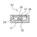
- a white light emitting device 30 may include a package body 31 having a reflective cup formed in a central portion thereof, a blue LED 35 mounted on the bottom of the reflective cup, and a transparent resin encapsulation unit 39 disposed within the reflective cup and encapsulating the blue LED 35 , similarly to the foregoing embodiment. Resin layers containing different phosphors may be provided on the resin encapsulation unit 39 .
- a wavelength conversion unit may be configured to include a first resin layer 32 containing the green phosphor, a second resin layer 34 containing the yellow phosphor, and a third resin layer 36 containing the red phosphor.
- a sequence in which the first to third resin layers 32 , 34 and 36 are stacked may be changed as needed.
- a white light source module may be usefully employed as a light source for an LCD backlight unit. That is, the white light source module according to the embodiment may be provided as a light source for an LCD backlight unit and may be combined with several optical members, for example, a diffusion plate, alight guard plate, a reflective plate, a prism sheet, and the like, to thereby configure a backlight assembly.
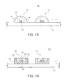
- FIGS. 15 and 16 illustrate white light source modules as above.
- a light source module 50 for an LCD backlight may include a circuit board 51 and a plurality of white LED devices 10 mounted thereon to be arrayed.
- a conductive pattern may be formed on an upper surface of the circuit board 51 to be connected to the LED devices 10 .
- the respective white LED device 10 illustrated in FIG. 15 may be considered to be the white LED device described with reference to FIG. 12 . That is, a blue LED 15 may be directly mounted on the circuit board 51 in a chip on board (COB) scheme.
- the configuration of respective white LED devices 10 may include a hemispheric resin encapsulation unit 19 having a lens function without a separate reflective wall, such that respective white LED devices 10 may have relatively wide beam angles. A wide angle of the spread beam of the respective white light source may contribute to a reduction in the size, for example, a thickness or a width, of an LCD display.
- a light source module 60 for an LCD backlight may include a circuit board 61 and a plurality of white LED devices 20 mounted thereon to be arrayed.
- the white LED device 20 may include the blue LED chip 25 mounted within the reflective cup in the package body 21 and the resin encapsulation unit 29 encapsulating the blue LED chip 25 , and the resin encapsulation unit 29 may include a yellow phosphor 22 and phosphors 24 and 26 emitting a color different therefrom, for example, green or red.
- FIGS. 17A and 17B are cross-sectional views illustrating examples of a back light unit according to various embodiments.
- a backlight unit in which a light emitting diode package according to an embodiment of the inventive concept is applied as alight source an edge-type backlight unit 1300 is illustrated in FIG. 17A .
- the edge-type backlight unit 1300 according to the present embodiment may include a light guide plate 1340 and LED light source modules 1310 provided on both sides of the light guide plate 1340 .
- the LED light source module 1310 may only be disposed on a single side thereof, and unlike the description above, additional LED light source modules may also be provided on other sides.
- a reflective plate 1320 may be further provided on a lower part of the light guide plate 1340 .
- the LED light source module 1310 used in the present embodiment may include a printed circuit board 1301 and a plurality of LED light sources 1305 mounted on the board 1301 , and the LED light sources 1305 may be provided using a light emitting device package employing the foregoing phosphor, to be applied thereto.
- FIG. 17B illustrates a direct-type backlight unit 1400 .
- the direct-type backlight unit 1400 may include a light diffusion plate 1440 and LED light source modules 1410 arrayed on a lower surface of the light diffusion plate 1440 .
- the backlight unit 1400 illustrated in FIG. 17B may include a bottom case 1460 provided with a lower part of the light diffusion plate 1440 and receiving the light source modules.
- the LED light source module 1410 employed in the present embodiment may include the printed circuit board 1401 and the plurality of LED light sources 1405 mounted on an upper surface of the printed circuit board 1401 .
- the plurality of LED light sources may be light emitting device packages using the above-mentioned phosphors as wavelength conversion materials.
- a direct-type backlight unit 1500 may include a phosphor film 1550 and an LED light source module 1510 arrayed on a lower surface of the phosphor film 1550 .
- the backlight unit 1500 illustrated in FIG. 18 may include a bottom case 1560 receiving the light source module 1510 .
- the phosphor film 1550 may be disposed on an upper surface of the bottom case 1560 .
- a wavelength of at least a portion of light emitted from the light source module 1510 may be changed by the phosphor film 1550 .
- the phosphor film 1550 may be manufactured as a separate film to be applied, the phosphor film 1550 may be provided in a form in which it is integrated with the light diffusion plate.
- the LED light source module 1510 may include a printed circuit board 1501 and a plurality of LED light sources 1505 mounted on the printed circuit board 1501 .
- FIGS. 19A and 19B illustrate edge-type backlight units according to embodiments of the inventive concept.
- An edge-type backlight unit 1600 shown in FIG. 19A may include a light guide plate 1640 and an LED light source 1605 provided with one side of the light guide plate 1640 . Light from the LED light source 1605 may be guided to the interior of the light guide plate 1640 through a reflective structure 1620 .
- a phosphor film 1650 may be interposed between a side of the light guide plate 1640 and the LED light source 1605 .
- An edge-type backlight unit 1700 shown in FIG. 19B may include alight guide plate 1740 and an LED light source 1705 and a reflective structure 1720 provided with one side of the light guide plate 1740 .
- the present embodiment illustrates a manner in which a phosphor film 1750 is applied to a light emission surface of the light guide plate.
- the phosphor according to the embodiment may also be implemented to be applied to other devices such as a backlight unit or the like instead of being directly applied to the LED light source.
- FIG. 20 is an exploded perspective view of a display device according to an embodiment.
- the display device 2400 shown in FIG. 20 may include a backlight unit 2200 and an image display panel 2300 such as a liquid crystal panel.
- the backlight unit 2200 may include a light guide plate 2240 and an LED light source module 2100 provided on at least one side of the light guide plate 2240 .
- the backlight unit 2200 may further include a bottom case 2210 and a reflective plate 2220 disposed below the light guide plate 2240 as shown in FIG. 20 .
- the display device may include several types of optical sheets 2260 such as a diffusion sheet, a prism sheet or a protective sheet between the light guide plate 2240 and the liquid crystal panel 2300 .
- the LED light source module 2100 may include a printed circuit board 2110 provided with at least one side of the light guide plate 2240 and a plurality of LED light sources 2150 mounted on the printed circuit substrate 2110 to allow light to be incident onto the light guide plate 2240 .
- the plurality of LED light sources 2150 may be the above-mentioned light emitting device packages.
- the plurality of LED light sources employed in the present embodiment may be side view-type light emitting device packages of which sides adjacent to a light emission surface are mounted.
- the above-mentioned phosphor may be applied to a package having various mounting structures to be applied to an LED light source module providing various types of white light.
- the above-mentioned light emitting device package or the above-mentioned light source module including the same may be applied to various types of display devices or illumination apparatuses.
- a high brightness ⁇ -SiAlON-based phosphor having relatively high light emission efficiency may be provided, and a white light emitting device, a surface light source device, an illumination device and a display device using the phosphor as described above may be provided.
Landscapes
- Chemical & Material Sciences (AREA)
- Inorganic Chemistry (AREA)
- Engineering & Computer Science (AREA)
- Materials Engineering (AREA)
- Organic Chemistry (AREA)
- Physics & Mathematics (AREA)
- General Physics & Mathematics (AREA)
- Optics & Photonics (AREA)
- Led Device Packages (AREA)
- Luminescent Compositions (AREA)
- Vessels And Coating Films For Discharge Lamps (AREA)
Applications Claiming Priority (3)
| Application Number | Priority Date | Filing Date | Title |
|---|---|---|---|
| KR10-2011-0047509 | 2011-05-19 | ||
| KR1020110047509A KR101772656B1 (ko) | 2011-05-19 | 2011-05-19 | 형광체 및 발광장치 |
| PCT/KR2012/003972 WO2012157998A2 (fr) | 2011-05-19 | 2012-05-18 | Matériau fluorescent, dispositif électroluminescent, dispositif de source de lumière planaire, dispositif d'affichage et dispositif d'éclairage |
Publications (2)
| Publication Number | Publication Date |
|---|---|
| US20140104874A1 US20140104874A1 (en) | 2014-04-17 |
| US9200200B2 true US9200200B2 (en) | 2015-12-01 |
Family
ID=47177516
Family Applications (1)
| Application Number | Title | Priority Date | Filing Date |
|---|---|---|---|
| US14/118,324 Active 2032-12-31 US9200200B2 (en) | 2011-05-19 | 2012-05-18 | Phosphor, light emitting device, surface light source device, display device and illumination device |
Country Status (3)
| Country | Link |
|---|---|
| US (1) | US9200200B2 (fr) |
| KR (1) | KR101772656B1 (fr) |
| WO (1) | WO2012157998A2 (fr) |
Cited By (1)
| Publication number | Priority date | Publication date | Assignee | Title |
|---|---|---|---|---|
| US20140264170A1 (en) * | 2011-10-12 | 2014-09-18 | Ube Industries, Ltd. | Oxynitride phosphor powder, silicon nitride powder for production of oxynitride phosphor powder, and production method of oxynitride phosphor powder |
Families Citing this family (3)
| Publication number | Priority date | Publication date | Assignee | Title |
|---|---|---|---|---|
| KR102164079B1 (ko) * | 2014-05-30 | 2020-10-12 | 엘지이노텍 주식회사 | 산질화물계 형광체를 포함하는 발광 소자 패키지 |
| JP2017073412A (ja) * | 2015-10-05 | 2017-04-13 | 株式会社ジャパンディスプレイ | 表示装置及び光源装置 |
| DE102016104875A1 (de) * | 2016-03-16 | 2017-09-21 | Osram Opto Semiconductors Gmbh | Optoelektronisches Bauelement, Verfahren zur Herstellung eines optoelektronischen Bauelements und Blitzlichtbeleuchtung für ein tragbares Gerät |
Citations (12)
| Publication number | Priority date | Publication date | Assignee | Title |
|---|---|---|---|---|
| JP2002363554A (ja) | 2001-06-07 | 2002-12-18 | National Institute For Materials Science | 希土類元素を付活させた酸窒化物蛍光体 |
| US20030030038A1 (en) | 2001-06-07 | 2003-02-13 | National Institute For Materials Science | Oxynitride phosphor activated by a rare earth element, and sialon type phosphor |
| US20030030368A1 (en) | 2001-07-16 | 2003-02-13 | Patent-Treuhand-Gesellschaft Fur Elektrische Gluehlampen Mbh | Illumination unit having at least one LED as light source |
| JP2003336059A (ja) | 2002-05-23 | 2003-11-28 | National Institute For Materials Science | サイアロン系蛍光体 |
| JP2006257326A (ja) | 2005-03-18 | 2006-09-28 | National Institute For Materials Science | Yb系α−サイアロン蛍光体 |
| JP3914991B2 (ja) | 2003-11-27 | 2007-05-16 | 独立行政法人物質・材料研究機構 | サイアロン蛍光体の製造方法 |
| US20070246732A1 (en) | 2004-08-30 | 2007-10-25 | Fujikura Ltd. | Oxynitride phosphor and a light emitting device |
| WO2010087348A1 (fr) | 2009-01-27 | 2010-08-05 | 電気化学工業株式会社 | LUMINOPHORE À BASE D'α-SIALON, SON PROCÉDÉ DE PRODUCTION ET DISPOSITIF ÉLECTROLUMINESCENT |
| US20100237767A1 (en) | 2006-05-10 | 2010-09-23 | Hideyuki Emoto | Sialon phosphor, process for producing the same, and illuminator and luminescent element employing the same |
| US20100244067A1 (en) * | 2006-11-17 | 2010-09-30 | Merck Patent Gesellschaft | Phosphor plates for leds from structured films |
| KR20110016493A (ko) | 2008-08-13 | 2011-02-17 | 우베 고산 가부시키가이샤 | Li 함유 α-사이알론계 형광체와 그 제조방법, 조명 기구 및 화상 표시 장치 |
| US8294848B2 (en) * | 2008-10-01 | 2012-10-23 | Samsung Display Co., Ltd. | Liquid crystal display having light diffusion layer |
-
2011
- 2011-05-19 KR KR1020110047509A patent/KR101772656B1/ko active Active
-
2012
- 2012-05-18 WO PCT/KR2012/003972 patent/WO2012157998A2/fr not_active Ceased
- 2012-05-18 US US14/118,324 patent/US9200200B2/en active Active
Patent Citations (21)
| Publication number | Priority date | Publication date | Assignee | Title |
|---|---|---|---|---|
| US20030030038A1 (en) | 2001-06-07 | 2003-02-13 | National Institute For Materials Science | Oxynitride phosphor activated by a rare earth element, and sialon type phosphor |
| JP2002363554A (ja) | 2001-06-07 | 2002-12-18 | National Institute For Materials Science | 希土類元素を付活させた酸窒化物蛍光体 |
| US20030030368A1 (en) | 2001-07-16 | 2003-02-13 | Patent-Treuhand-Gesellschaft Fur Elektrische Gluehlampen Mbh | Illumination unit having at least one LED as light source |
| US6657379B2 (en) | 2001-07-16 | 2003-12-02 | Patent-Treuhand-Gesellschaft Fur Elektrische Gluehlampen Mbh | Illumination unit having at least one LED as light source |
| JP4288047B2 (ja) | 2001-07-16 | 2009-07-01 | パテント−トロイハント−ゲゼルシヤフト フユール エレクトリツシエ グリユーラムペン ミツト ベシユレンクテル ハフツング | 光源として少なくとも1つのledを備えた照明ユニット |
| JP2003336059A (ja) | 2002-05-23 | 2003-11-28 | National Institute For Materials Science | サイアロン系蛍光体 |
| JP3914991B2 (ja) | 2003-11-27 | 2007-05-16 | 独立行政法人物質・材料研究機構 | サイアロン蛍光体の製造方法 |
| US7597821B2 (en) | 2004-08-30 | 2009-10-06 | Fujikura Ltd. | Oxynitride phosphor and a light emitting device |
| US20070246732A1 (en) | 2004-08-30 | 2007-10-25 | Fujikura Ltd. | Oxynitride phosphor and a light emitting device |
| KR100772047B1 (ko) | 2004-08-30 | 2007-10-31 | 가부시키가이샤후지쿠라 | 산질화물 형광체 및 발광 장치 |
| JP2006257326A (ja) | 2005-03-18 | 2006-09-28 | National Institute For Materials Science | Yb系α−サイアロン蛍光体 |
| US20100237767A1 (en) | 2006-05-10 | 2010-09-23 | Hideyuki Emoto | Sialon phosphor, process for producing the same, and illuminator and luminescent element employing the same |
| KR20110004916A (ko) | 2006-05-10 | 2011-01-14 | 덴끼 가가꾸 고교 가부시키가이샤 | 사이알론 형광체 및 그 제조 방법 및 그것을 이용한 조명기구 및 발광소자 |
| US20120270049A1 (en) | 2006-05-10 | 2012-10-25 | Denki Kagaku Kogyo Kabushiki Kaisha | Sialon phosphor, process for producing the same, and illuminator and luminescent element employing the same |
| US20130193600A1 (en) | 2006-05-10 | 2013-08-01 | Denki Kagaku Kogyo Kabushiki Kaisha | Sialon phosphor, process for producing the same, and illuminator and luminescent element employing the same |
| US20100244067A1 (en) * | 2006-11-17 | 2010-09-30 | Merck Patent Gesellschaft | Phosphor plates for leds from structured films |
| KR20110016493A (ko) | 2008-08-13 | 2011-02-17 | 우베 고산 가부시키가이샤 | Li 함유 α-사이알론계 형광체와 그 제조방법, 조명 기구 및 화상 표시 장치 |
| US20110133629A1 (en) | 2008-08-13 | 2011-06-09 | Ube Industries, Ltd. | Li-containing alpha-sialon-based phosphor, production process thereof, lighting device and image display device |
| US8294848B2 (en) * | 2008-10-01 | 2012-10-23 | Samsung Display Co., Ltd. | Liquid crystal display having light diffusion layer |
| WO2010087348A1 (fr) | 2009-01-27 | 2010-08-05 | 電気化学工業株式会社 | LUMINOPHORE À BASE D'α-SIALON, SON PROCÉDÉ DE PRODUCTION ET DISPOSITIF ÉLECTROLUMINESCENT |
| US20110279018A1 (en) | 2009-01-27 | 2011-11-17 | Hideyuki Emoto | Alpha-sialon phosphor, method for producing same, and light-emitting device |
Non-Patent Citations (6)
| Title |
|---|
| International Preliminary Report on Patentability dated Nov. 19, 2013 issued in International Application No. PCT/KR2012/003972. |
| International Search Report dated Dec. 12, 2012 issued in corresponding International Application No. PCT/KR2012/003972. |
| Sakuma, K., et al., "Luminescence properties of (Ca, Y)-alpha-SiAION:Eu phosphors", ScienceDirect, Materials Letters 61 (2007) p. 547-550, © 2006 Elsevier B.V. |
| Sakuma, K., et al., "Luminescence properties of (Ca, Y)-alpha-SiAlON:Eu phosphors", ScienceDirect, Materials Letters 61 (2007) p. 547-550, © 2006 Elsevier B.V. |
| Sakuma, K., et al., "Luminescence properties of (Ca, Y)-α-SiAION:Eu phosphors", ScienceDirect, Materials Letters 61 (2007) p. 547-550, © 2006 Elsevier B.V. |
| Sakuma, K., et al., "Luminescence properties of (Ca, Y)-α-SiAlON:Eu phosphors", ScienceDirect, Materials Letters 61 (2007) p. 547-550, © 2006 Elsevier B.V. |
Cited By (2)
| Publication number | Priority date | Publication date | Assignee | Title |
|---|---|---|---|---|
| US20140264170A1 (en) * | 2011-10-12 | 2014-09-18 | Ube Industries, Ltd. | Oxynitride phosphor powder, silicon nitride powder for production of oxynitride phosphor powder, and production method of oxynitride phosphor powder |
| US9758720B2 (en) * | 2011-10-12 | 2017-09-12 | Ube Industries, Ltd. | Oxynitride phosphor powder, silicon nitride powder for production of oxynitride phosphor powder, and production method of oxynitride phosphor powder |
Also Published As
| Publication number | Publication date |
|---|---|
| KR101772656B1 (ko) | 2017-08-29 |
| WO2012157998A3 (fr) | 2013-03-21 |
| KR20120129330A (ko) | 2012-11-28 |
| WO2012157998A2 (fr) | 2012-11-22 |
| US20140104874A1 (en) | 2014-04-17 |
Similar Documents
| Publication | Publication Date | Title |
|---|---|---|
| CN102227826B (zh) | 显示装置用照明装置和显示装置 | |
| CN102403438B (zh) | 发光装置 | |
| US7737621B2 (en) | Light emitting device provided with a wavelength conversion unit incorporating plural kinds of phosphors | |
| US9087968B2 (en) | White light emitting device, display apparatus and illumination apparatus | |
| KR100946015B1 (ko) | 백색 발광장치 및 이를 이용한 lcd 백라이트용 광원모듈 | |
| US20180022993A1 (en) | Fluoride phosphor composite, method of manufacturing fluoride phosphor composite, white light emitting apparatus, display apparatus, lighting device, and electronic device | |
| US8129735B2 (en) | LED with controlled angular non-uniformity | |
| US20120306356A1 (en) | Fluorescent substance, light emitting device, surface light source device, display device and illuminating device | |
| US20110006668A1 (en) | Lighting Structures Including Diffuser Particles Comprising Phosphor Host Materials | |
| US20090315053A1 (en) | Light emitting device | |
| US20130020931A1 (en) | White light emitting device, and display apparatus and illumination apparatus using the same | |
| US12369438B2 (en) | System and method for providing color light sources in proximity to predetermined wavelength conversion structures | |
| WO2009093427A1 (fr) | Dispositif électroluminescent | |
| JP2008227523A (ja) | 窒化物蛍光体及びその製造方法並びに窒化物蛍光体を用いた発光装置 | |
| US10833230B2 (en) | Wavelength converting member and light emitting device | |
| CN102782887A (zh) | 卤磷酸盐荧光体及白色发光装置 | |
| US9200200B2 (en) | Phosphor, light emitting device, surface light source device, display device and illumination device | |
| US20120092853A1 (en) | Light emitting module | |
| US9559271B2 (en) | Oxynitride-based phosphor and white light emitting device including the same | |
| JPWO2014010211A1 (ja) | 発光モジュール | |
| CN119029117A (zh) | 发光装置 | |
| KR20130079803A (ko) | 백색 발광 장치 및 이를 이용한 디스플레이 및 조명장치 | |
| KR20110092426A (ko) | 백색 발광 다이오드 패키지 및 그 패키지를 구비한 백라이트 모듈 |
Legal Events
| Date | Code | Title | Description |
|---|---|---|---|
| AS | Assignment |
Owner name: SAMSUNG ELECTRONICS CO., LTD., KOREA, REPUBLIC OF Free format text: ASSIGNMENT OF ASSIGNORS INTEREST;ASSIGNORS:PARK, WOO-JUNG;YUN, BONG-GOO;SONG, WON-YOUNG;AND OTHERS;SIGNING DATES FROM 20130823 TO 20130830;REEL/FRAME:031621/0198 |
|
| STCF | Information on status: patent grant |
Free format text: PATENTED CASE |
|
| MAFP | Maintenance fee payment |
Free format text: PAYMENT OF MAINTENANCE FEE, 4TH YEAR, LARGE ENTITY (ORIGINAL EVENT CODE: M1551); ENTITY STATUS OF PATENT OWNER: LARGE ENTITY Year of fee payment: 4 |
|
| MAFP | Maintenance fee payment |
Free format text: PAYMENT OF MAINTENANCE FEE, 8TH YEAR, LARGE ENTITY (ORIGINAL EVENT CODE: M1552); ENTITY STATUS OF PATENT OWNER: LARGE ENTITY Year of fee payment: 8 |