US9207015B2 - Dryer having evaporator equipped with second condenser - Google Patents
Dryer having evaporator equipped with second condenser Download PDFInfo
- Publication number
- US9207015B2 US9207015B2 US14/057,226 US201314057226A US9207015B2 US 9207015 B2 US9207015 B2 US 9207015B2 US 201314057226 A US201314057226 A US 201314057226A US 9207015 B2 US9207015 B2 US 9207015B2
- Authority
- US
- United States
- Prior art keywords
- evaporator
- condenser
- refrigerant
- refrigerant pipe
- dryer
- Prior art date
- Legal status (The legal status is an assumption and is not a legal conclusion. Google has not performed a legal analysis and makes no representation as to the accuracy of the status listed.)
- Expired - Fee Related, expires
Links
Images




Classifications
-
- F26B21/086—
-
- F—MECHANICAL ENGINEERING; LIGHTING; HEATING; WEAPONS; BLASTING
- F26—DRYING
- F26B—DRYING SOLID MATERIALS OR OBJECTS BY REMOVING LIQUID THEREFROM
- F26B21/00—Arrangements for supplying or controlling air or other gases for drying solid materials or objects
- F26B21/30—Controlling, e.g. regulating, parameters of gas supply
- F26B21/33—Humidity
- F26B21/333—Humidity by condensing the moisture in the drying medium, which may be recycled, e.g. using a heat pump cycle
-
- D—TEXTILES; PAPER
- D06—TREATMENT OF TEXTILES OR THE LIKE; LAUNDERING; FLEXIBLE MATERIALS NOT OTHERWISE PROVIDED FOR
- D06F—LAUNDERING, DRYING, IRONING, PRESSING OR FOLDING TEXTILE ARTICLES
- D06F58/00—Domestic laundry dryers
- D06F58/02—Domestic laundry dryers having dryer drums rotating about a horizontal axis
-
- D—TEXTILES; PAPER
- D06—TREATMENT OF TEXTILES OR THE LIKE; LAUNDERING; FLEXIBLE MATERIALS NOT OTHERWISE PROVIDED FOR
- D06F—LAUNDERING, DRYING, IRONING, PRESSING OR FOLDING TEXTILE ARTICLES
- D06F58/00—Domestic laundry dryers
- D06F58/02—Domestic laundry dryers having dryer drums rotating about a horizontal axis
- D06F58/04—Details
-
- D—TEXTILES; PAPER
- D06—TREATMENT OF TEXTILES OR THE LIKE; LAUNDERING; FLEXIBLE MATERIALS NOT OTHERWISE PROVIDED FOR
- D06F—LAUNDERING, DRYING, IRONING, PRESSING OR FOLDING TEXTILE ARTICLES
- D06F58/00—Domestic laundry dryers
- D06F58/20—General details of domestic laundry dryers
- D06F58/206—Heat pump arrangements
-
- F—MECHANICAL ENGINEERING; LIGHTING; HEATING; WEAPONS; BLASTING
- F25—REFRIGERATION OR COOLING; COMBINED HEATING AND REFRIGERATION SYSTEMS; HEAT PUMP SYSTEMS; MANUFACTURE OR STORAGE OF ICE; LIQUEFACTION SOLIDIFICATION OF GASES
- F25B—REFRIGERATION MACHINES, PLANTS OR SYSTEMS; COMBINED HEATING AND REFRIGERATION SYSTEMS; HEAT PUMP SYSTEMS
- F25B39/00—Evaporators; Condensers
- F25B39/02—Evaporators
-
- F—MECHANICAL ENGINEERING; LIGHTING; HEATING; WEAPONS; BLASTING
- F25—REFRIGERATION OR COOLING; COMBINED HEATING AND REFRIGERATION SYSTEMS; HEAT PUMP SYSTEMS; MANUFACTURE OR STORAGE OF ICE; LIQUEFACTION SOLIDIFICATION OF GASES
- F25B—REFRIGERATION MACHINES, PLANTS OR SYSTEMS; COMBINED HEATING AND REFRIGERATION SYSTEMS; HEAT PUMP SYSTEMS
- F25B39/00—Evaporators; Condensers
- F25B39/04—Condensers
Definitions
- This relates to a dryer, and more particularly, to a dryer having enhanced dehumidifying power.
- a laundry treating apparatus having a drying function such as a washer or dryer
- hot air may be supplied into the drum to evaporate moisture from the laundry, thereby drying the laundry.
- a dryer may include a drum rotatably provided within a cabinet, a drive motor to drive the drum, a blower fan to blow air into the drum, and a heating device to heat air conveyed into the drum.
- the heating device may use, for example, high-temperature electric resistance heat generated using electric resistance, or combustion heat generated by combusting gas.
- FIG. 1 is a side view of an internal structure of a heat pump type dryer
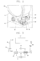
- FIG. 2 is a partial detail view of a circulation type heat pump within the dryer shown in FIG. 1 ;
- FIG. 3 is a schematic diagram of a drying method carried out by the heat pump shown in FIG. 2 ;
- FIG. 4 illustrates a refrigerant circulation path of an evaporator in an exemplary heat pump
- FIG. 5 is a schematic diagram of a circulation path of refrigerant using an additional condenser integrated with an evaporator, in accordance with embodiments as broadly described herein;
- FIGS. 6 and 7 illustrate a refrigerant circulation path in an evaporator and an additional condenser integrated with an evaporator, in accordance with embodiments as broadly described herein;
- FIG. 8 is a graph showing enhanced dehumidifying performance according to enhanced heat exchange efficiency.
- Dryers may be classified according to a method for processing the high temperature humid air discharged from the drum as a condensation (circulation) type dryer for condensing moisture contained in the high temperature humid air by cooling the air below the dew point temperature while it circulates, without discharging the high temperature humid air out of the dryer, or an exhaustion type dryer for directly discharging the high temperature humid air from the drum to the outside.
- a condensation (circulation) type dryer for condensing moisture contained in the high temperature humid air by cooling the air below the dew point temperature while it circulates, without discharging the high temperature humid air out of the dryer, or an exhaustion type dryer for directly discharging the high temperature humid air from the drum to the outside.
- the air in order to condense air discharged from the drum, the air may be cooled below the dew point temperature and then heated by the heating device prior to being supplied to the drum again.
- loss of heat energy contained in the air may be generated while being cooled down during the condensation process, and an additional heater or the like may further heat the air to a temperature required for drying.
- the high temperature humid air is discharged to the outside and outside air at a normal (room) temperature is drawn in and heated to a required temperature level by the heating device.
- a normal (room) temperature is drawn in and heated to a required temperature level by the heating device.
- residual thermal energy contained in the high temperature air being discharged to the outside may be wasted, thereby reducing thermal efficiency.
- a laundry treating apparatus for collecting energy to generate hot air and unused energy being discharged to the outside may increase energy efficiency, such as, for example, a laundry treating apparatus having a heat pump system.
- the heat pump system may include two heat exchangers, a compressor and an expansion apparatus, and energy contained in the discharged hot air may be reused to heat air being supplied to the drum, thereby increasing energy efficiency.
- an evaporator may be provided at the exhaust side of the drum, and a condenser at an inlet side of the drum, and thus thermal energy may be transferred to refrigerant through the evaporator and then thermal energy contained in the refrigerant may be transferred to air conveyed into the drum, thereby generating hot air using waste energy.
- a heater for reheating air that has been heated while passing through the evaporator may also be provided.
- the size of the condenser may be somewhat restricted due to a lack of space, thereby causing difficulty in achieving the desired condensation effect. Accordingly, heat exchange efficiency may be reduced and the cooling of refrigerant may not be properly carried out, thereby reducing dehumidifying capability.
- a dryer may include a cabinet 100 and a drum 110 rotatably provided within the cabinet 100 .
- the drum 110 may be rotatably supported by a supporter, for example, at the front and rear ends thereof.
- An intake duct 170 may be provided in the cabinet 100 to draw outside air into the cabinet 100 and supply the air to the drum 110 .
- the intake duct 170 may extend in the vertical direction at the rear of the drum 110 , and may define an intake flow path.
- the air drawn in through the intake duct 170 may be drawn in from outside of the cabinet 100 , separately from the drying duct 190 .
- a heater 180 for heating the air to an adequate temperature for drying may be provided within the intake duct 170 .
- the heater 180 may receive electrical energy to sufficiently and quickly supply heating to air to be supplied to the drum 110 , and also so that the refrigerant cycle may be stably managed in a normal state.
- heating required for drying may be sufficiently supplied in a relatively short period of time, thereby reducing drying time.
- additional heating may be supplied in a short period of time when necessary to further heat the air flowing in the circulation flow path.
- the air supplied to the drum 110 may be supplied through a circulation flow path formed in the drying duct 190 , separately from the air provided through the intake flow path formed in the intake duct 170 .
- the drying duct 190 may be provided in the cabinet 100 to circulate air discharged from the drum 110 back to the drum 110 .
- the air in the drum 110 dries/absorbs moisture from the laundry and then flows into a front surface duct located at a lower front side of the drum 110 , and is supplied back to the drum 110 through the drying duct 190 by way of a lint filter, or is discharged to the outside of the cabinet 100 through an exhaust duct.
- a blower fan 120 to forcibly blow air to the outside of the dryer may be provided on the circulation flow path formed by the drying duct 190 .
- An evaporator 130 and a condenser 140 may be sequentially provided on a flow path formed by the drying duct 190 .
- the evaporator 130 and condenser 140 forming a kind of heat exchanger, may form a refrigerant cycle of the heat pump, thereby achieving heat exchange with air (Ad) on the circulation flow path.
- the air supplied to the drum 110 may be heated by the heater 180 on the intake flow path or the condenser 140 on the circulation flow path to become high-temperature dry air at about 150-250° C. when supplied back into the drum 110 .
- the high-temperature air may contact an object to be dried to evaporate moisture therefrom.
- the evaporated moisture will then be contained in intermediate temperature air exhausted out of the drum 110 .
- the moisture may be removed from this intermediate temperature humid air so that it may be circulated and re-used. Since the moisture content in the air is affected by the temperature, the moisture may be removed by cooling the air. Accordingly, the air on the circulation flow path may be cooled by heat exchange with the evaporator 130 . In order to supply the air cooled by the evaporator 130 back to the drum 110 at an appropriate temperature for drying, it may be heated by high temperature air, carried out by the condenser 140 .
- a refrigerant cycle may perform heat exchange with the environment using phase change(s) of refrigerant.
- refrigerant may be transformed into a low-temperature and low-pressure gas by absorbing heat from the environment in the evaporator, compressed into a high-temperature and high-pressure gas in the compressor, transformed into a high-temperature and high-pressure liquid by dissipating heat to the environment in the condenser, transformed into a low-temperature and low-pressure liquid by dropping its pressure in the expansion apparatus, and brought into the evaporator again. Due to the circulation of refrigerant, heat may be absorbed from the environment in the evaporator and heat may be supplied to the environment in the condenser.
- the refrigerant cycle may be also referred to as a heat pump.
- Such a refrigerant cycle may include the compressor 150 and expansion apparatus 160 along with the evaporator 130 and condenser 140 .
- FIGS. 2 and 3 The flow path of air in heat exchange with the refrigerant cycle is illustrated in FIGS. 2 and 3 .
- an arrow passing through the evaporator and condenser and a line connecting the evaporator and condenser does not indicate the flow path of the refrigerant. Rather, these arrows indicate the flow path of the air in FIGS. 2 and 3 , which is sequentially brought into contact with the evaporator 130 and the like to perform heat exchange.
- the evaporator 130 and condenser 140 may be sequentially disposed on the circulation flow path (a large circulation line formed along a bold arrow in FIG. 3 ) formed by the drying duct 190 .
- the air (Ad) on the circulation flow path performs heat exchange with the heat pump during the refrigerant cycle, specifically the air (Ad) on the circulation flow path dissipates heat in heat exchange with the evaporator 130 , and absorbs heat in heat exchange with the condenser 140 . As a result, the air on the circulation flow path re-absorbs heat it has dissipated.
- the evaporator 130 and condenser 140 may mainly be in charge of heat exchange during the refrigerant cycle, and the air from which heat is taken in the evaporator 130 liquefies moisture contained therein to exhaust it as condensation water, so that dry air may be heated by the compressor 150 and condenser 140 to be changed into high temperature dry air.
- the high-temperature air may be provided into the drum 110 along with the air from the intake flow path to perform the drying process. Part of the air provided to the drum and used in the drying process is exhausted to the outside of the dryer 100 , and part is reused.
- waste heat may be collected using the refrigerant cycle, without causing an overload during the refrigerant cycle.
- the heat exchange of refrigerant may be carried out by phase change(s) at optimal operating temperature and pressure, and to this end, a heat exchanger such as an evaporator and a condenser, a compressor, an expansion apparatus and the like may be used. Accordingly, in order to collect more heat, the size of the heat exchanger or compressor may be increased. However, due to limited installation space in the dryer, the size of these components may be somewhat limited.
- the heater 180 may be provided within the intake duct 170 to continuously replenish the inhaled air with heating. According to embodiments as broadly described herein, heating may be replenished by the heater 180 to sufficiently supply the heating required for drying, thereby reducing drying time. Furthermore, the heat exchange of refrigerant may be carried out by phase change(s) at optimal operating temperature(s) and pressure(s), and to this end, heating may be sufficiently supplied. Otherwise, it may cause a problem such as refrigerant being supplied to the compressor in a liquid phase or the like, and thus the cycle cannot be stably operated, thereby reducing the reliability of the cycle. Accordingly, as disclosed herein, the air provided to the drum may be additionally replenished with heating by the heater 180 , and thus the refrigerant cycle may be stably operated in a normal state.
- the additional blower fan 120 may be provided on the intake flow path to provide more airflow, and prevent the heater 180 from overheating, as shown in FIGS. 2 through 4 .
- the laundry treating apparatus may further include an exhaust duct 15 branched from the drying duct 190 , upstream of the evaporator 130 and may exhaust part of the air to the outside of the cabinet 100 .
- the exhaust duct 15 may form an exhaust flow path for discharging hot air coming out of the drum 110 to the outside.
- waste heat may be absorbed from part of the intermediate temperature humid air coming out of the drum 110 within a range that can be processed by the refrigerant cycle, and the rest of the air is exhausted. Accordingly, energy waste may be reduced overload during the refrigerant cycle may be avoided. Furthermore, it may be possible to reduce power consumption as well as enhance reliability.
- the exemplary evaporator 130 shown in FIG. 4 is formed on a single refrigerant path with one inlet 131 and one outlet 132 , and the pipe line Pe of the evaporator may pass through a plurality of overlapped plate shaped heat dissipation fins and may extend vertically in a zigzag pattern.
- Refrigerant flowing into the evaporator 130 through the inlet 131 from the expansion apparatus 160 flows along the refrigerant line of the evaporator 130 to perform heat exchange, and is then circulated to the compressor 150 through the outlet 132 of the refrigerant pipe of the evaporator 130 .
- the evaporator 130 merely performs a heat exchange operation with high temperature and humid air in the dryer to reduce the temperature of the air and extract condensation water. Furthermore, air flowing through the condenser 140 is heated to allow the high temperature and humid air to flow back into the drum 110 . Due to this, in a dryer as embodied and broadly described herein, the condenser 140 may function as a first condenser 140 , and a second condenser 141 may be provided in the evaporator 130 to further increase a heating change, thereby enhancing heat exchange efficiency.
- refrigerant follows a path through the compressor 150 , the first condenser 140 , expansion apparatus 160 and the evaporator 130 .
- refrigerant that has passed through the compressor 150 is condensed in the first condenser 140 , and then condensed again in the second condenser 141 separately provided in the evaporator 130 , thereby enhancing a condensation effect.
- the evaporator 130 may include the second condenser 141 configured to condense refrigerant (P2) that has already been condensed in the first condenser 140 .
- Refrigerant (P4) condensed again in the second condenser may be is circulated to the expansion apparatus 160 .
- refrigerant (P4) coming out of the expansion apparatus 160 may be circulated along the refrigerant pipe of the evaporator 130 to supercool refrigerant during the refrigerant cycle, thereby enhancing dehumidifying capability in the evaporator 130 .
- refrigerant (P5) coming through the evaporator 130 may pass through the compressor 150 , and the compressed refrigerant (P1) flows to the refrigerant pipe of the condenser 140 again.
- the refrigerant pipe of the evaporator 130 and the refrigerant pipe of the second condenser 141 may be intrusively formed in the same heat dissipation fins.
- the heat dissipation fin may be formed such that a plurality of plate-shaped metals having excellent thermal conductivity overlap with one another to efficiently perform external heat exchange with the refrigerant flowing through the refrigerant pipe. In this manner, a degree of supercooling may be further increased through the first condensation carried out by the first condenser 140 and the second condensation carried out by the second condenser 141 to enhance dehumidifying capability in the evaporator 130 , thereby enhancing the efficiency of the heat pump.
- the refrigerant cycle in a condensation type dryer having a heat pump may enhance dehumidifying capability in the evaporator 130 for removing moisture in the dry flow path.
- refrigerant flowing into the pipe from the first condenser 140 outlet passes through the second condenser 141 without directly passing through the expansion apparatus 160 .
- it has a structure in which refrigerant in the second condenser 141 may be further supercooled and brought into the evaporator 130 in a low temperature dry state through the expansion apparatus 160 , thereby enhancing dehumidifying capability.
- the second condenser 141 may be vertically arranged at the rear end, or downstream end, of the evaporator 130 , or horizontally arranged at the lower bottom end thereof, as illustrated in FIGS. 6 and 7 , respectively, which illustrate the refrigerant flow path structure of an evaporator in which a partial refrigerant plumbing pipe of the evaporator 130 is independently plumbed in place of the second condenser 141 .
- the refrigerant pipe of the evaporator 130 may be vertically arranged in a zigzag pattern, and the lowest end portion of the refrigerant pipe may be disposed at a condensation water line of condensation water accumulated below the evaporator 130 , at a bottom of the drying duct 190 , and the refrigerant pipe Pc2 of the second condenser 141 may be vertically arranged in a zigzag pattern at the rear end with respect to the flow direction of dry air, or downstream end.
- the disposition and arrangement of the pipe plumbing of the second condenser 141 may maximize heat exchange efficiency by causing air to first pass through the second condenser 141 and then pass through the first condenser 140 since the moisture is removed and the temperature is reduced while high temperature and humid air (Ad) first passes through the evaporator 130 .
- the refrigerant pipe plumbing path of the evaporator 130 is configured with one path, and the refrigerant pipe plumbing path of the second condenser 141 is formed with an independent refrigerant line separated from the plumbing flow path of the evaporator 130 .
- the refrigerant pipe plumbing path of the evaporator 130 may include one path vertically arranged in a zigzag pattern in four columns, and the refrigerant pipe plumbing path of the second condenser 141 may include one path vertically arranged in a zigzag pattern in one column, as shown in FIG. 6 .
- FIG. 6 the refrigerant pipe plumbing path of the evaporator 130 may include one path vertically arranged in a zigzag pattern in four columns, and the refrigerant pipe plumbing path of the second condenser 141 may include one path vertically arranged in a zigzag pattern in one column, as shown in FIG. 6 .
- FIG. 6 FIG.
- FIG. 6 illustrates a structure in which the front, or upstream, end (left side in the drawing) first through fourth columns of the evaporator 130 is used for the evaporator plumbing performing refrigerant dehumidification and air cooling portions, and the last, fifth, column of the rear, or downstream, end (right side in the drawing) is used for the plumbing of the second condenser 141 to increase the degree of supercooling of the refrigerant.
- refrigerant may be evaporated in the evaporator plumbing (first through fourth columns from the front end) to transfer the heat of vaporization to external high temperature and humid air (Ad), thereby allowing moisture in the air to be cooled into condensation water.
- dry air at ambient temperature that has passed through the evaporator 130 may be heat transferred to the second condenser 141 through condenser refrigerant in a portion (the fifth column, at the rear end) used for the second condenser 141 , thereby increasing the degree of supercooling of the refrigerant due to the second condenser 141 .
- the refrigerant pipe plumbing path of the evaporator 130 may be vertically arranged in a zigzag pattern, and the refrigerant pipe plumbing path Pc2 of the second condenser 141 may be arranged so that it is submerged under condensation water below a condensation water line at a lower portion of the evaporator 130 , and horizontally arranged in a zigzag pattern.
- the heat of vaporization at an upper portion of the evaporator 130 may be transferred and then the generated condensation water may flow down due to gravity since the second condenser 141 is provided at the lower portion, thereby increasing the degree of supercooling due to a temperature difference between condensation water and refrigerant while passing through the second condenser 141 .
- the first condenser 140 which is a heat pump system
- the second condenser 141 the expansion apparatus 160 , the evaporator 130 and the compressor 150 are connected to circulate refrigerant along a refrigerant circulation line so as to form a refrigerant cycle.
- the refrigerant cycle may perform a second condensing operation on refrigerant (P2) coming out of the first condenser 140 through the second condenser 141 to increase the degree of supercooling of the refrigerant (P3) coming out of the second condenser 141 by ⁇ Q.
- the enthalpy of refrigerant (P3) coming out of the second condenser 141 may be less than that of refrigerant (P2) coming out of the first condenser 140 .
- the dehumidifying performance of the evaporator 130 may be enhanced by approximately 400 W during the refrigerant cycle due to a difference ( ⁇ Q) between the enthalpy of refrigerant (P2) coming out of the first condenser 140 and the enthalpy of refrigerant (P3) coming out of the second condenser 141 .
- the refrigerant is phase-changed to the state (2) (refrigerant in the phase of P2). Then, a degree of supercooling using the second condenser 141 according to the present disclosure is increased to the location of (3) (refrigerant in the phase of P3) from that of (2) (refrigerant in the phase of P2).
- a heat absorption start location in the evaporator 130 is moved to the location of (4) (P4), and thus it is seen that the dehumidifying performance is enhanced from 2600 W (in a system not employing such a second condenser) to 3000 W, from enthalpy (4) to enthalpy (5), by about 400 W.
- the second condenser 141 may be integrally added to the evaporator 130 to supercool refrigerant in the refrigerant cycle and maximize a condensation effect, thereby enhancing heat exchange efficiency.
- the second condenser 141 may be positioned along a path separated from the refrigerant line of the evaporator 130 , thereby enhancing dehumidifying performance by about 400 W due to condensation water cooling providing enhanced heat exchange efficiency.
- a dryer employing a circulation type heat pump in which a second condenser is integrally added to an evaporator to supercool refrigerant in the refrigerant cycle and maximize a condensation effect, thereby enhancing heat exchange efficiency.
- a dryer employing a heat pump structure in which a second condenser is configured through a path separated from the refrigerant line of the evaporator, in the rear heat or lower heat of the evaporator, thereby promoting heat exchange efficiency enhanced through cool dry air or lower condensation water, and enhancing dehumidifying performance by about 400 W.
- a heat pump type dryer as embodied and broadly described herein may include a cabinet, a drum rotatably provided within the cabinet, a drying duct provided in the cabinet to circulate air discharged from the drum by resupplying it thereto, an evaporator and a first condenser sequentially provided on a flow path formed by the drying duct, and a compressor and an expansion apparatus configured to form a refrigerant cycle along with the evaporator and the first condenser.
- the evaporator may include a second condenser to condense refrigerant condensed from the first condenser again, and the refrigerant pipe of the evaporator and the refrigerant pipe of the second condenser may be intrusively formed in the same heat dissipation fins to supercool refrigerant during the refrigerant cycle, thereby enhancing dehumidifying capability in the evaporator.
- the refrigerant pipe of the evaporator and the refrigerant pipe of the second condenser may be intrusively formed in the same heat dissipation fins.
- the refrigerant pipe of the evaporator may be vertically arranged in a zigzag pattern, and the lowest end portion of the refrigerant pipe may be disposed on the condensation water line, and the refrigerant pipe of the second condenser may be vertically arranged in a zigzag pattern at the rear side with respect to the flow direction of dry air.
- the refrigerant pipe plumbing path of the evaporator may be configured with one path, and the refrigerant pipe plumbing path of the second condenser may be formed with an independent refrigerant line separated from the pluming flow path of the evaporator.
- the refrigerant pipe plumbing path of the evaporator may be formed with one path vertically arranged in a zigzag pattern with four columns, and the refrigerant pipe plumbing path of the second condenser may be formed with one path vertically arranged in a zigzag pattern with one column.
- the refrigerant pipe plumbing path of the evaporator may be vertically arranged in a zigzag pattern, and the refrigerant pipe plumbing path of the second condenser may be disposed to be submerged under condensation water below a condensation water line at a lower portion of the evaporator, and horizontally arranged in a zigzag pattern.
- the first condenser, the second condenser, the expansion apparatus, the evaporator and the compressor may be connected to circulate refrigerant along a refrigerant circulation line so as to form a refrigerant cycle.
- the refrigerant cycle may perform a second condensing operation on refrigerant (P2) coming out of the first condenser through the second condenser to increase the supercooling degree of refrigerant (P3) coming out of the second condenser.
- the enthalpy of refrigerant (P3) coming out of the second condenser may be less than that of refrigerant (P2) coming out of the first condenser.
- the dehumidifying performance of the evaporator may be enhanced by 400 W during the refrigerant cycle due to a difference ( ⁇ Q) between the enthalpy of refrigerant (P2) coming out of the first condenser and the enthalpy of refrigerant (P3) coming out of the second condenser.
- any reference in this specification to “one embodiment,” “an embodiment,” “example embodiment,” etc. means that a particular feature, structure, or characteristic described in connection with the embodiment is included in at least one embodiment of the invention.
- the appearances of such phrases in various places in the specification are not necessarily all referring to the same embodiment.
Landscapes
- Engineering & Computer Science (AREA)
- Textile Engineering (AREA)
- Mechanical Engineering (AREA)
- General Engineering & Computer Science (AREA)
- Detail Structures Of Washing Machines And Dryers (AREA)
Applications Claiming Priority (2)
| Application Number | Priority Date | Filing Date | Title |
|---|---|---|---|
| KR10-2012-0117469 | 2012-10-22 | ||
| KR1020120117469A KR101987695B1 (ko) | 2012-10-22 | 2012-10-22 | 2차 응축기가 설치된 증발기를 구비한 의류건조기 |
Publications (2)
| Publication Number | Publication Date |
|---|---|
| US20140109426A1 US20140109426A1 (en) | 2014-04-24 |
| US9207015B2 true US9207015B2 (en) | 2015-12-08 |
Family
ID=49378180
Family Applications (1)
| Application Number | Title | Priority Date | Filing Date |
|---|---|---|---|
| US14/057,226 Expired - Fee Related US9207015B2 (en) | 2012-10-22 | 2013-10-18 | Dryer having evaporator equipped with second condenser |
Country Status (7)
| Country | Link |
|---|---|
| US (1) | US9207015B2 (fr) |
| EP (1) | EP2725132B1 (fr) |
| KR (1) | KR101987695B1 (fr) |
| AU (2) | AU2013245520B2 (fr) |
| BR (1) | BR102013026926B1 (fr) |
| DE (1) | DE202013104698U1 (fr) |
| RU (1) | RU2557737C2 (fr) |
Cited By (9)
| Publication number | Priority date | Publication date | Assignee | Title |
|---|---|---|---|---|
| CN105487584A (zh) * | 2016-01-12 | 2016-04-13 | 河南佰衡节能科技股份有限公司 | 一种热泵式烤房环境湿度控制系统 |
| US20160186374A1 (en) * | 2014-12-29 | 2016-06-30 | Lg Electronics Inc. | Clothes treating apparatus |
| US20170002506A1 (en) * | 2014-03-21 | 2017-01-05 | Electrolux Appliances Aktiebolag | Laundry Drying Machine |
| CN109883158A (zh) * | 2019-03-25 | 2019-06-14 | 杨鑫 | 一种高效率对流烘干机 |
| US20190264379A1 (en) * | 2016-01-05 | 2019-08-29 | Lg Electronics Inc. | Clothes treatment apparatus having heat pump module |
| US10508384B2 (en) | 2009-06-29 | 2019-12-17 | Electrolux Home Products Corporation N.V. | Top of an appliance for drying laundry providing drying air recirculation and moisture condensation |
| US10519592B2 (en) | 2009-06-29 | 2019-12-31 | Electrolux Home Products Corporation N.V. | Appliance for drying laundry providing drying air recirculation and moisture condensation |
| US20220162795A1 (en) * | 2020-11-20 | 2022-05-26 | Samsung Electronics Co., Ltd. | Dryer |
| US12435456B2 (en) | 2022-01-25 | 2025-10-07 | Samsung Electronics Co., Ltd. | Washing machine with drying function |
Families Citing this family (12)
| Publication number | Priority date | Publication date | Assignee | Title |
|---|---|---|---|---|
| KR101987695B1 (ko) * | 2012-10-22 | 2019-06-11 | 엘지전자 주식회사 | 2차 응축기가 설치된 증발기를 구비한 의류건조기 |
| US20160102426A1 (en) * | 2014-10-08 | 2016-04-14 | General Electric Company | Laundry dryer with heat shield |
| CN106192322A (zh) * | 2015-04-29 | 2016-12-07 | 青岛海尔洗衣机有限公司 | 一种冷凝干衣机及冷凝干衣方法 |
| CN106283569B (zh) * | 2015-05-22 | 2020-04-14 | 青岛海尔洗衣机有限公司 | 干衣机及其控制方法 |
| CN107642951B (zh) * | 2016-07-28 | 2019-09-17 | 中国科学院理化技术研究所 | 一种混合式热泵干燥系统 |
| KR20180014615A (ko) * | 2016-08-01 | 2018-02-09 | 엘지전자 주식회사 | 의류처리장치 |
| KR20180019385A (ko) * | 2016-08-16 | 2018-02-26 | 엘지전자 주식회사 | 의류처리장치 |
| CN106984142A (zh) * | 2017-04-21 | 2017-07-28 | 深圳市捷晶能源科技有限公司 | 一种除湿干燥系统与除湿干燥方法 |
| CN108759329A (zh) * | 2018-06-28 | 2018-11-06 | 江苏必领能源科技有限公司 | 闭式除湿水风热泵多烘房烘干系统 |
| CN110057168A (zh) * | 2019-03-12 | 2019-07-26 | 浙江海洋大学 | 一种节能型热泵水产品烘干装置 |
| CN110057169B (zh) * | 2019-03-12 | 2024-09-17 | 浙江海洋大学 | 一种水产品热泵型干燥装置 |
| EP4253636A1 (fr) * | 2022-03-31 | 2023-10-04 | V-Zug AG | Séchoir pourvu d'échangeur de chaleur supplémentaire |
Citations (19)
| Publication number | Priority date | Publication date | Assignee | Title |
|---|---|---|---|---|
| US3290793A (en) * | 1963-04-29 | 1966-12-13 | Gen Motors Corp | Dry cleaner with refrigerated solvent reclaiming system |
| DE4409607A1 (de) * | 1993-04-21 | 1994-10-27 | Miele & Cie | Kondensationswäschetrockner mit einer Wärmepumpe |
| EP0999302A1 (fr) * | 1998-10-21 | 2000-05-10 | Whirlpool Corporation | Sèche-linge à tambour avec pompe à chaleur |
| US20050204755A1 (en) * | 2002-09-26 | 2005-09-22 | Matsushita Electric Industrial Co., Ltd. | Drying apparatus |
| US7020985B2 (en) * | 2004-03-26 | 2006-04-04 | Whirlpool Corporation | Multiple outlet air path for a clothes dryer |
| WO2009059889A1 (fr) * | 2007-11-06 | 2009-05-14 | BSH Bosch und Siemens Hausgeräte GmbH | Appareil électroménager possédant une unité de pompe à chaleur et moyens de refroidissement d'un composant de celle-ci |
| WO2011080116A1 (fr) | 2009-12-31 | 2011-07-07 | Arcelik Anonim Sirketi | Sèche-linge à pompe à chaleur |
| WO2011088116A1 (fr) | 2010-01-13 | 2011-07-21 | Advanced Reactor Concepts LLC | Combustible nucléaire en métal annulaire chemisé |
| US8082677B2 (en) * | 2007-02-23 | 2011-12-27 | Electrolux Home Products Corporation, N.V. | Home laundry drier |
| US20120246962A1 (en) | 2011-03-29 | 2012-10-04 | Lee Junseok | Clothes dryer |
| EP2573252A1 (fr) * | 2011-09-26 | 2013-03-27 | Electrolux Home Products Corporation N.V. | Appareil de traitement du linge avec pompe à chaleur |
| WO2013045363A1 (fr) | 2011-09-27 | 2013-04-04 | Arcelik Anonim Sirketi | Sèche-linge doté d'une pompe à chaleur |
| US8418377B2 (en) * | 2007-11-06 | 2013-04-16 | Bsh Bosch Und Siemens Hausgeraete Gmbh | Dryer with heat pump |
| US8601717B2 (en) * | 2010-07-26 | 2013-12-10 | General Electric Company | Apparatus and method for refrigeration cycle capacity enhancement |
| US8615895B2 (en) * | 2010-05-13 | 2013-12-31 | Samsung Electronics Co., Ltd. | Clothes dryer |
| US20140041400A1 (en) * | 2010-12-27 | 2014-02-13 | Electrolux Home Products Corporation N.V. | Heat pump system for a laundry dryer and a method for operating a heat pump laundry dryer |
| US20140109428A1 (en) * | 2012-10-22 | 2014-04-24 | Seonghwan Kim | Dryer |
| US20140109426A1 (en) * | 2012-10-22 | 2014-04-24 | Seungphyo AHN | Dryer having evaporator equipped with second condenser |
| US8707581B2 (en) * | 2010-08-25 | 2014-04-29 | Electrolux Home Products Corporation N.V. | Laundry treating machine with basement portion having multi-level air flow path |
Family Cites Families (7)
| Publication number | Priority date | Publication date | Assignee | Title |
|---|---|---|---|---|
| DE4307372A1 (de) * | 1993-03-09 | 1994-09-15 | Licentia Gmbh | Programmgesteuerter Wäschetrockner mit einem Wärmepumpenkreis |
| CN2595848Y (zh) * | 2002-12-20 | 2003-12-31 | 华东船舶工业学院 | 热泵式干衣机 |
| JP4888025B2 (ja) * | 2006-10-05 | 2012-02-29 | パナソニック株式会社 | 乾燥装置 |
| DE102007002181B3 (de) * | 2007-01-15 | 2008-08-21 | BSH Bosch und Siemens Hausgeräte GmbH | Kondensationstrockner mit einer Wärmepumpe |
| JP2011092510A (ja) * | 2009-10-30 | 2011-05-12 | Toshiba Corp | 衣類乾燥機 |
| EP2385169A1 (fr) * | 2010-05-03 | 2011-11-09 | Electrolux Home Products Corporation N.V. | Machine à laver avec système de pompe à chaleur et procédé de fonctionnement de la machine à laver |
| EP2460926A1 (fr) * | 2010-12-02 | 2012-06-06 | Electrolux Home Products Corporation N.V. | Séchoir à pompe thermique |
-
2012
- 2012-10-22 KR KR1020120117469A patent/KR101987695B1/ko not_active Expired - Fee Related
-
2013
- 2013-09-20 RU RU2013142950/12A patent/RU2557737C2/ru active
- 2013-10-18 AU AU2013245520A patent/AU2013245520B2/en not_active Ceased
- 2013-10-18 DE DE202013104698.1U patent/DE202013104698U1/de not_active Expired - Lifetime
- 2013-10-18 BR BR102013026926-3A patent/BR102013026926B1/pt not_active IP Right Cessation
- 2013-10-18 EP EP13189242.4A patent/EP2725132B1/fr not_active Not-in-force
- 2013-10-18 US US14/057,226 patent/US9207015B2/en not_active Expired - Fee Related
-
2018
- 2018-04-13 AU AU2018100480A patent/AU2018100480B4/en not_active Ceased
Patent Citations (20)
| Publication number | Priority date | Publication date | Assignee | Title |
|---|---|---|---|---|
| US3290793A (en) * | 1963-04-29 | 1966-12-13 | Gen Motors Corp | Dry cleaner with refrigerated solvent reclaiming system |
| DE4409607A1 (de) * | 1993-04-21 | 1994-10-27 | Miele & Cie | Kondensationswäschetrockner mit einer Wärmepumpe |
| EP0999302A1 (fr) * | 1998-10-21 | 2000-05-10 | Whirlpool Corporation | Sèche-linge à tambour avec pompe à chaleur |
| US20050204755A1 (en) * | 2002-09-26 | 2005-09-22 | Matsushita Electric Industrial Co., Ltd. | Drying apparatus |
| US7020985B2 (en) * | 2004-03-26 | 2006-04-04 | Whirlpool Corporation | Multiple outlet air path for a clothes dryer |
| US8082677B2 (en) * | 2007-02-23 | 2011-12-27 | Electrolux Home Products Corporation, N.V. | Home laundry drier |
| WO2009059889A1 (fr) * | 2007-11-06 | 2009-05-14 | BSH Bosch und Siemens Hausgeräte GmbH | Appareil électroménager possédant une unité de pompe à chaleur et moyens de refroidissement d'un composant de celle-ci |
| US8418377B2 (en) * | 2007-11-06 | 2013-04-16 | Bsh Bosch Und Siemens Hausgeraete Gmbh | Dryer with heat pump |
| WO2011080116A1 (fr) | 2009-12-31 | 2011-07-07 | Arcelik Anonim Sirketi | Sèche-linge à pompe à chaleur |
| WO2011088116A1 (fr) | 2010-01-13 | 2011-07-21 | Advanced Reactor Concepts LLC | Combustible nucléaire en métal annulaire chemisé |
| US8615895B2 (en) * | 2010-05-13 | 2013-12-31 | Samsung Electronics Co., Ltd. | Clothes dryer |
| US8601717B2 (en) * | 2010-07-26 | 2013-12-10 | General Electric Company | Apparatus and method for refrigeration cycle capacity enhancement |
| US8707581B2 (en) * | 2010-08-25 | 2014-04-29 | Electrolux Home Products Corporation N.V. | Laundry treating machine with basement portion having multi-level air flow path |
| US20140041400A1 (en) * | 2010-12-27 | 2014-02-13 | Electrolux Home Products Corporation N.V. | Heat pump system for a laundry dryer and a method for operating a heat pump laundry dryer |
| US20120246962A1 (en) | 2011-03-29 | 2012-10-04 | Lee Junseok | Clothes dryer |
| EP2573252A1 (fr) * | 2011-09-26 | 2013-03-27 | Electrolux Home Products Corporation N.V. | Appareil de traitement du linge avec pompe à chaleur |
| US20140223758A1 (en) * | 2011-09-26 | 2014-08-14 | Electrolux Home Products Corporation N.V. | Laundry Treatment Apparatus with Heat Pump |
| WO2013045363A1 (fr) | 2011-09-27 | 2013-04-04 | Arcelik Anonim Sirketi | Sèche-linge doté d'une pompe à chaleur |
| US20140109428A1 (en) * | 2012-10-22 | 2014-04-24 | Seonghwan Kim | Dryer |
| US20140109426A1 (en) * | 2012-10-22 | 2014-04-24 | Seungphyo AHN | Dryer having evaporator equipped with second condenser |
Non-Patent Citations (2)
| Title |
|---|
| Russian Decision to Grant a Patent dated Mar. 25, 2015 issued in Application No. 2013142950 (with English translation). |
| Russian Office Action issued in related Application No. 2013142950 dated Dec. 26, 2014 (with English translation). |
Cited By (14)
| Publication number | Priority date | Publication date | Assignee | Title |
|---|---|---|---|---|
| US10508384B2 (en) | 2009-06-29 | 2019-12-17 | Electrolux Home Products Corporation N.V. | Top of an appliance for drying laundry providing drying air recirculation and moisture condensation |
| US10519592B2 (en) | 2009-06-29 | 2019-12-31 | Electrolux Home Products Corporation N.V. | Appliance for drying laundry providing drying air recirculation and moisture condensation |
| US20170002506A1 (en) * | 2014-03-21 | 2017-01-05 | Electrolux Appliances Aktiebolag | Laundry Drying Machine |
| US9845567B2 (en) * | 2014-03-21 | 2017-12-19 | Electrolux Appliances Aktiebolag | Laundry drying machine |
| US20160186374A1 (en) * | 2014-12-29 | 2016-06-30 | Lg Electronics Inc. | Clothes treating apparatus |
| US9803313B2 (en) * | 2014-12-29 | 2017-10-31 | Lg Electronics Inc. | Clothes treating apparatus |
| US20190264379A1 (en) * | 2016-01-05 | 2019-08-29 | Lg Electronics Inc. | Clothes treatment apparatus having heat pump module |
| US10988894B2 (en) * | 2016-01-05 | 2021-04-27 | Lg Electronics Inc. | Clothes treatment apparatus having heat pump module |
| CN105487584A (zh) * | 2016-01-12 | 2016-04-13 | 河南佰衡节能科技股份有限公司 | 一种热泵式烤房环境湿度控制系统 |
| CN109883158A (zh) * | 2019-03-25 | 2019-06-14 | 杨鑫 | 一种高效率对流烘干机 |
| CN109883158B (zh) * | 2019-03-25 | 2024-04-26 | 杨鑫 | 一种高效率对流烘干机 |
| US20220162795A1 (en) * | 2020-11-20 | 2022-05-26 | Samsung Electronics Co., Ltd. | Dryer |
| US12338570B2 (en) * | 2020-11-20 | 2025-06-24 | Samsung Electronics Co., Ltd. | Dryer |
| US12435456B2 (en) | 2022-01-25 | 2025-10-07 | Samsung Electronics Co., Ltd. | Washing machine with drying function |
Also Published As
| Publication number | Publication date |
|---|---|
| BR102013026926A2 (pt) | 2014-08-19 |
| EP2725132A2 (fr) | 2014-04-30 |
| AU2013245520A1 (en) | 2014-05-08 |
| AU2013245520B2 (en) | 2018-01-18 |
| KR101987695B1 (ko) | 2019-06-11 |
| RU2557737C2 (ru) | 2015-07-27 |
| AU2018100480A4 (en) | 2018-05-17 |
| RU2013142950A (ru) | 2015-03-27 |
| KR20140050982A (ko) | 2014-04-30 |
| EP2725132B1 (fr) | 2019-07-31 |
| AU2018100480B4 (en) | 2019-11-07 |
| EP2725132A3 (fr) | 2016-03-30 |
| DE202013104698U1 (de) | 2014-01-29 |
| US20140109426A1 (en) | 2014-04-24 |
| BR102013026926B1 (pt) | 2021-07-20 |
Similar Documents
| Publication | Publication Date | Title |
|---|---|---|
| US9207015B2 (en) | Dryer having evaporator equipped with second condenser | |
| EP2725133B1 (fr) | Sèche-linge | |
| US9146056B2 (en) | Laundry treating apparatus having expansion valve which is variable according to the driving mode | |
| US9200841B2 (en) | Clothes dryer | |
| CN104233735B (zh) | 一种热泵干衣机及干衣方法 | |
| CN102822410A (zh) | 干衣机 | |
| JP2009066398A (ja) | ダクトレス乾燥機 | |
| WO2010003936A1 (fr) | Sèche-linge du type pompe à chaleur | |
| EP2385169A1 (fr) | Machine à laver avec système de pompe à chaleur et procédé de fonctionnement de la machine à laver | |
| WO2010140334A1 (fr) | Dispositif de séchage | |
| KR102063765B1 (ko) | 폐열 회수수단을 갖는 건조기 | |
| KR101694158B1 (ko) | 세탁물 처리장치 | |
| CN1837452A (zh) | 一种半导体除湿式干衣机及干衣方法 | |
| JP2016123770A (ja) | 洗濯乾燥機 | |
| CN106988104A (zh) | 半导体热泵除湿干衣系统及干衣方法 | |
| KR20120014531A (ko) | 의류건조기 | |
| JP2010281500A (ja) | 乾燥装置 | |
| KR101241914B1 (ko) | 건조기 | |
| KR101085217B1 (ko) | 간접 냉각방식의 용제회수기 |
Legal Events
| Date | Code | Title | Description |
|---|---|---|---|
| AS | Assignment |
Owner name: LG ELECTRONICS INC., KOREA, REPUBLIC OF Free format text: ASSIGNMENT OF ASSIGNORS INTEREST;ASSIGNORS:AHN, SEUNGPHYO;NOH, HYUNWOO;LEE, HYUKSOO;REEL/FRAME:031433/0111 Effective date: 20131007 |
|
| STCF | Information on status: patent grant |
Free format text: PATENTED CASE |
|
| FEPP | Fee payment procedure |
Free format text: PAYOR NUMBER ASSIGNED (ORIGINAL EVENT CODE: ASPN); ENTITY STATUS OF PATENT OWNER: LARGE ENTITY |
|
| MAFP | Maintenance fee payment |
Free format text: PAYMENT OF MAINTENANCE FEE, 4TH YEAR, LARGE ENTITY (ORIGINAL EVENT CODE: M1551); ENTITY STATUS OF PATENT OWNER: LARGE ENTITY Year of fee payment: 4 |
|
| FEPP | Fee payment procedure |
Free format text: MAINTENANCE FEE REMINDER MAILED (ORIGINAL EVENT CODE: REM.); ENTITY STATUS OF PATENT OWNER: LARGE ENTITY |
|
| LAPS | Lapse for failure to pay maintenance fees |
Free format text: PATENT EXPIRED FOR FAILURE TO PAY MAINTENANCE FEES (ORIGINAL EVENT CODE: EXP.); ENTITY STATUS OF PATENT OWNER: LARGE ENTITY |
|
| STCH | Information on status: patent discontinuation |
Free format text: PATENT EXPIRED DUE TO NONPAYMENT OF MAINTENANCE FEES UNDER 37 CFR 1.362 |
|
| FP | Lapsed due to failure to pay maintenance fee |
Effective date: 20231208 |