US9213908B2 - Method for registering at least one part of a first and second image using a collineation warping function - Google Patents
Method for registering at least one part of a first and second image using a collineation warping function Download PDFInfo
- Publication number
- US9213908B2 US9213908B2 US14/006,859 US201114006859A US9213908B2 US 9213908 B2 US9213908 B2 US 9213908B2 US 201114006859 A US201114006859 A US 201114006859A US 9213908 B2 US9213908 B2 US 9213908B2
- Authority
- US
- United States
- Prior art keywords
- image
- warping function
- orientation
- measurements
- collineation
- Prior art date
- Legal status (The legal status is an assumption and is not a legal conclusion. Google has not performed a legal analysis and makes no representation as to the accuracy of the status listed.)
- Active, expires
Links
Images


Classifications
-
- G—PHYSICS
- G06—COMPUTING OR CALCULATING; COUNTING
- G06T—IMAGE DATA PROCESSING OR GENERATION, IN GENERAL
- G06T3/00—Geometric image transformations in the plane of the image
- G06T3/18—Image warping, e.g. rearranging pixels individually
-
- G06K9/32—
-
- G06T3/0093—
-
- G06T7/0028—
-
- G—PHYSICS
- G06—COMPUTING OR CALCULATING; COUNTING
- G06T—IMAGE DATA PROCESSING OR GENERATION, IN GENERAL
- G06T7/00—Image analysis
- G06T7/30—Determination of transform parameters for the alignment of images, i.e. image registration
- G06T7/33—Determination of transform parameters for the alignment of images, i.e. image registration using feature-based methods
-
- G—PHYSICS
- G06—COMPUTING OR CALCULATING; COUNTING
- G06V—IMAGE OR VIDEO RECOGNITION OR UNDERSTANDING
- G06V10/00—Arrangements for image or video recognition or understanding
- G06V10/20—Image preprocessing
- G06V10/24—Aligning, centring, orientation detection or correction of the image
-
- G—PHYSICS
- G06—COMPUTING OR CALCULATING; COUNTING
- G06T—IMAGE DATA PROCESSING OR GENERATION, IN GENERAL
- G06T2207/00—Indexing scheme for image analysis or image enhancement
- G06T2207/30—Subject of image; Context of image processing
- G06T2207/30204—Marker
- G06T2207/30208—Marker matrix
-
- G—PHYSICS
- G06—COMPUTING OR CALCULATING; COUNTING
- G06T—IMAGE DATA PROCESSING OR GENERATION, IN GENERAL
- G06T2207/00—Indexing scheme for image analysis or image enhancement
- G06T2207/30—Subject of image; Context of image processing
- G06T2207/30244—Camera pose
Definitions
- the present invention relates to a method for registering at least one part of a first and second image using a collineation warping function. Moreover, the present invention relates to a computer program product comprising software code sections for implementing the method.
- Such a method is often required in computer vision applications such as augmented reality (AR) applications.
- AR augmented reality
- many applications in the field of computer vision require to spatially register at least part of a second image I which is a current camera image to it.
- Examples include panorama stitching and camera pose estimation, for example for a video-see-through augmented reality application.
- the transformation of any part of the template corresponding to a planar surface to its corresponding position in a current camera image is composed of a 3D translation followed by a 3D rotation and finally a perspective projection onto the image plane.
- This transformation can be fully described with a collineation W representing a perspective transformation between the 2D points on the template and the 2D corresponding points in the camera image.
- the collineation is often represented by a (3 ⁇ 3) matrix that is invertible.
- the matrix is defined up to a scale and has eight degrees of freedom and could be written as:
- the collineation defines a one-to-one and onto warping.
- the collineation warping is called affine warping when the entries p 7 and p 8 of the corresponding matrix are equal to zeros.
- the collineation can then be represented with a matrix
- the affine warping preserves parallelism and ratio of distances.
- the collineation warping corresponding to that planar surface is an affine warping.
- FIG. 1 A standard approach for finding a transformation as mentioned above is displayed in FIG. 1 .
- a first step S 1 one or multiple template or reference images (first image) are captured by a camera or loaded from a source. Then at first, a current image (second image) is either captured or loaded (step S 2 ). In the next step S 3 the actual estimation takes place.
- a collineation warping function has to be found that registers at least part of the current image and the corresponding position in the template image. Among other techniques, this can be done in an iterative minimization process where a first set of pixels in the template image is compared with a computed set of pixels in the current camera image and the computed set of pixels in the camera image used for the comparison varies at each iteration, see for example [2].
- step S 4 the found collineation warping function W is used in an application.
- the authors in [3] use the orientation of a mobile capturing device measured by accelerometers to rectify images they use as a template image. During alignment of current camera images with the template image, they do however not consider the orientation of the device at all.
- a method for registering at least one part of a first and a second image comprising the steps of:
- the present invention proposes to reduce the complexity of finding the collineation warping function W as mentioned above, needed to spatially register a captured current image with a template image by incorporating the measured orientation of the capturing device.
- the collineation warping function W may be decomposed into a collineation warping function P that can be computed directly from the measured orientation, followed by an affine transformation A that needs to be estimated.
- Finding A is cheaper and more stable than finding W as it requires fewer parameters to be estimated, as set out in more detail below.
- the measurements of orientation are provided by at least one of an inertial sensor, an accelerometer, a gyroscope, a compass, or a mechanical, electromagnetic, acoustic, or optical tracking system.
- an inertial sensor may, e.g. continuously, provide sensor information including the position and/or orientation of an object or device with regard to the environment, by using any combination of the following: magnetometer (e.g. a compass), motion sensor/rotation sensor (accelerometers/gyroscopes), gravity sensor, and other sensors providing such information.
- the measurements of distance are provided by at least one of a time-of-flight camera, a stereo camera, triangulation of radio signals, difference of phase measurements, or a device using a structured-light-based approach.
- a sensor providing distance information may be a device using a structured-light-based approach where the light is visible or infra-red (e.g. Microsoft's known Kinect camera).
- the measurements of orientation comprise a two-dimensional rotation computed based on a measurement of a gravity vector.
- the at least one part of the first image corresponds to a physical object placed at a known orientation with respect the measured gravity vector.
- the collineation warping function may then be related to a virtual image plane which is at the known orientation with respect to the measured gravity vector.
- the measurements of orientation include a three-dimensional rotation of a capturing device with respect to the real environment while capturing the second image by the capturing device.
- the orientation of a capturing device with respect to the coordinate system associated to the first image is computed and used for determining the collineation warping function in step d).
- the collineation warping function may be related to a virtual image plane aligned to the coordinate system.
- the distance of the capturing device to a physical object is determined for computing a one-dimensional translation of the capturing device in the coordinate system.
- the orientation is determined from the measurements of distance of a set of N points in the second image, wherein N is at least three.
- the first and/or second image is an image of an three-dimensional physical object which is assumed to be piece-wise planar.
- the second warping function is an affine warping function.
- the image registration method is based on an iterative minimization process, wherein a first set of pixels in the first image is compared with a computed set of pixels in the second image and the computed set of pixels in the second image used for the comparison varies at each iteration.
- the comparison in the registration is based on image intensity differences.
- a photometric error may be computed. This error may be used in the cost function of a non-linear optimization that searches for an update of a parameter set.
- the second warping function can be determined with a method using gradient descent such as the inverse compositional, inverse additive, forward compositional or the forward additive approach, as described in [6]. Further, the second warping function can determined with a learning-based method where different views of the template image (first image) have been pre-computed and the closest pre-computed transformation to the current transformation is determined, such as described in [1] or [7].
- an initial estimate of the parameters of the second warping function may be provided to the iterative minimization process.
- the initial estimate of the parameters of the warping function is determined using an estimate of a motion of the capturing device between capturing the first image and capturing the second image.
- step c) at least a third image (e.g., one or more further template images) and a respective associated coordinate system are further provided, and the second image at least partly contains an object of the first image and of the at least third image, wherein steps d)-g) are conducted for the first image and the at least third image individually.
- a third image e.g., one or more further template images
- the second image at least partly contains an object of the first image and of the at least third image
- the first image and/or at least third image and their associated coordinate systems are acquired offline
- the first image and/or at least third image and their associated coordinate systems are acquired and/or updated online.
- the transformation between coplanar horizontal areas in two or more current images can be found in the same way.
- all images need to be projected onto the virtual image plane.
- the result of the registering of the at least one part of the second image is used for determining the pose of the capturing device.
- the determined pose of the capturing device is used in an augmented reality application.
- Another aspect of the invention is also related to a computer program product which is adapted to be loaded into the internal memory of a digital computer and comprises software code sections by means of which the method according to the invention is performed when said product is running on said computer.
- FIG. 1 shows a flow diagram of a standard approach for image registration
- FIG. 2 shows a flow diagram of an exemplary approach for image registration according to an embodiment of the invention
- FIG. 3 shows a flow diagram of an exemplary approach for image registration with at least a third image according to an embodiment of the invention
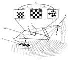
- FIG. 4 shows a visualization of a registering process of a template image and a current image captured by a camera according to an embodiment of the invention, using a known 3DoF camera orientation and a known arbitrary template orientation,
- FIG. 5 shows a visualization of another registering process of a template image and a current image captured by a camera according to an embodiment of the invention, using a known 2DoF camera orientation and a leveled template
- FIG. 6 shows a visualization of another registering process of a template image and a current image captured by a camera according to an embodiment of the invention, using a depth sensing camera and unknown arbitrary template orientation.
- a capturing device D such as a camera for capturing images of a real environment, with an estimate of the intrinsic parameters, i.e. the intrinsic camera parameters.
- Attached is a device that delivers measurements of the camera's orientation R either directly or determined from measured distances of at least three points in the environment and captured in the image.
- the explanation deals with a template image representing an orthofrontal view of a planar object and we aim to register the entire template T with the corresponding pixels in I.
- the method can also be generalized to targets that can be considered piece-wise planar. This can be simply done, for example, by associating parts of the template image to local planar regions of a physical object.
- FIG. 2 shows a flow diagram of an exemplary approach for image registration according to an embodiment of the invention.
- FIG. 2 shows an approach in general, which will be further explained according to examples as depicted in FIGS. 4-6 .
- the approach according to aspects of the invention for finding the collineation warping function W that registers at least part of a planar template T and its corresponding position in a current camera image I taken under an arbitrary viewing angle is to first capture or load a first image T as template with an associated coordinate system CS in step S 1 .
- a second image I as a current camera image is either loaded or captured.
- step S 3 the orientation of the capturing device (i.e. camera) is measured or the orientation at the time the second image was taken is loaded.
- the device orientation R, the coordinate system CS and the second image I are used in step S 4 to compute the projection of the second image I onto a virtual image plane VIP.
- This transformation is done with the collineation warping function P which is a function of the camera orientation R and CS.
- the transformation to register the transformed image Ip with the first image T is linear and can be described with an affine homography.
- This homography A is estimated in step S 5 (e.g., calculated in an iterative minimization process, for example using the known algorithm of Lucas Kanade [2]).
- homography A is an affine homography, estimating it is less computational complex than estimating a collineation warping function as described above with reference to standard approaches.
- a collineation warping function W transforming the at least one part of the original current image is computed as a combination of P and A.
- the application such as an augmented reality application, uses this projective transformation W.
- step S 5 both in step S 5 and step S 6 , the registration can be achieved by warping in either direction.
- A can be determined such that the transformed image Ip is registered to the first image T, or the inverse of A can be determined by registering the first image T to the transformed image Ip.
- step S 1 of FIG. 3 at least a third image T 3 with an associated coordinate system CS 3 is provided in addition to the first image T and its associated coordinate system CS.
- steps S 2 and S 3 of FIG. 3 a second image I is either captured or loaded and the orientation R of the capturing device D is measured or loaded.
- I and R are provided to the core algorithm registering the current image I with a template image in steps S 4 , S 5 and S 6 .
- Each template image with associated coordinate system i.e. the first and the at least third image, are processed by an instance of the core algorithm conducting steps S 4 -S 6 .
- the resulting collineation warping functions W, W 3 , . . . are finally used in an application in step S 7 .
- collineation warping function W is decomposed into a constrained, e.g. affine transformation A and a collineation warping function P that can be computed directly from the measured orientation R of the capturing device D.
- a constrained e.g. affine transformation A
- P collineation warping function
- FIG. 4 depicts a visualization of a registering to a planar template at an arbitrary but known orientation (i.e., a normal n of the planar template image T is known as well as the rotation for defining a vector u) and given the current 3DoF orientation of the capturing device.
- a normal n of the planar template image T is known as well as the rotation for defining a vector u
- the measured orientation R of the capturing device D describes a three-dimensional rotation with respect to a static world coordinate system
- n and u can be updated to account for drift of the orientation measures.
- any set of points lying on the template image T will be represented mathematically similar and upright. More precisely, the appearance in image Ip is the result of a uniform scaling followed by a translation of the original points in image T. Registering this transformed current image Ip to the template image T is then a three-dimensional non-linear optimization problem finding a linear warping as the transformation can be fully described with an affine homography A that only supports uniform scaling and translation in x and y (the two image axes).
- step S 3 may be implemented with any device capable of measuring the 3D orientation of the capturing device D in a global coordinate system
- the orientation measurement R is a 3D rotation in a global coordinate system
- P(x,p) represents the projection onto a virtual image plane VIP aligned with the device coordinate system
- A(x,p) is an affine homography supporting x,y,z translation (3D).
- FIG. 5 depicts a visualization of registering to a horizontal planar template given a 2DoF camera orientation relative to the gravity.
- Some sensors like inertial sensors only provide the 2-dimensional rotation of the capturing device with respect to the gravity vector.
- the orientation measurements R only describe the direction of the gravity vector.
- a similar approach as described with reference to FIG. 4 can be used that is limited to templates lying on a leveled (horizontal) plane, e.g. a magazine lying on a table, a mosaic on the floor or a painted ceiling
- a collineation warping function P we project the current camera image I onto a virtual image plane VIP which is perpendicular to the measured gravity n.
- the template image T is on a leveled plane
- step S 3 may be implemented with an accelerometer
- the orientation measurement R is the direction of the gravity and therefore a 2D rotation
- P(x,p) represents the projection onto a virtual image plane VIP perpendicular to the measured gravity
- A(x,p) is an affine homography supporting x,y,z translation and in-plane rotation (4D).
- FIG. 6 depicts a visualization of registering to an arbitrarily oriented planar template given the normal of the template in the camera coordinate system.
- the capturing device or an attached device D provides measured depth information for particular pixels of the current image I and if the intrinsic camera parameters are known, the 3D position of individual pixels in the coordinate system of the camera can be computed.
- the current camera image I has been successfully registered with the arbitrarily oriented template image T using a standard approach
- the assumption here is that these pixels still contain the template in the current image.
- the current camera image I projected to this virtual image plane VIP using the collineation warping function P will be called Ip.
- Spatially registering it with the template image T can be described with an affine homography A supporting translation in x and y (the image axes), in plane rotation and uniform scale.
- Step S 3 is implemented using a depth sensing camera such as the known Microsoft Kinect camera sampling the depth of at least three pixels in the camera image that are assumed to contain the template;
- the orientation measurement R is the direction of the normal of the template in the capturing device coordinate system and therefore a 2D rotation;
- P(x,p) represents the projection onto a virtual image plane VIP perpendicular to the measured normal of the template;
- A(x,p) is an affine homography supporting x,y,z translation and in-plane rotation (4D).
- the invention could be used in a real-time augmented reality application running on a mobile computing device equipped with a camera.
- the objective of the application is, e.g., to overlay virtual information such as computer graphic models on a live video stream capturing a real planar object lying on a horizontal surface.
- the overlay done in such application respects the relative pose between the camera and the planar object, meaning the computer graphic model is seamlessly integrated in the live video stream also when the mobile device is changing its position and orientation with respect to the planar object.
- the application running on the mobile computing device may include an algorithm that provides the relative position (3D translation) and orientation (3D rotation) of the camera with respect to the planar object lying on the horizontal surface.
- the 3D translation and rotation can be obtained from the (3 ⁇ 3) collineation matrix which means that the algorithm first finds the optimal (3 ⁇ 3) collineation matrix that transforms a reference image to the currently acquired image, and then extracts the 3D translation and rotation knowing the intrinsic parameters of the camera of the mobile computing device.
Landscapes
- Engineering & Computer Science (AREA)
- Physics & Mathematics (AREA)
- General Physics & Mathematics (AREA)
- Theoretical Computer Science (AREA)
- Multimedia (AREA)
- Computer Vision & Pattern Recognition (AREA)
- Image Analysis (AREA)
- Length Measuring Devices By Optical Means (AREA)
- Image Processing (AREA)
Applications Claiming Priority (1)
| Application Number | Priority Date | Filing Date | Title |
|---|---|---|---|
| PCT/EP2011/054456 WO2012126522A1 (fr) | 2011-03-23 | 2011-03-23 | Procédé permettant d'enregistrer au moins une partie d'une première et d'une seconde image à l'aide d'une fonction de déformation de type collinéation |
Publications (2)
| Publication Number | Publication Date |
|---|---|
| US20140086494A1 US20140086494A1 (en) | 2014-03-27 |
| US9213908B2 true US9213908B2 (en) | 2015-12-15 |
Family
ID=44625521
Family Applications (1)
| Application Number | Title | Priority Date | Filing Date |
|---|---|---|---|
| US14/006,859 Active 2031-12-08 US9213908B2 (en) | 2011-03-23 | 2011-03-23 | Method for registering at least one part of a first and second image using a collineation warping function |
Country Status (4)
| Country | Link |
|---|---|
| US (1) | US9213908B2 (fr) |
| EP (1) | EP2689393A1 (fr) |
| JP (1) | JP5781682B2 (fr) |
| WO (1) | WO2012126522A1 (fr) |
Cited By (2)
| Publication number | Priority date | Publication date | Assignee | Title |
|---|---|---|---|---|
| WO2017115271A1 (fr) * | 2015-12-30 | 2017-07-06 | Cimagine Media Ltd. | Procédé de suivi de plan |
| US12409557B2 (en) | 2021-11-12 | 2025-09-09 | Industrial Technology Research Institute | Training data generation device, training data generation method using the same and robot arm system using the same |
Families Citing this family (10)
| Publication number | Priority date | Publication date | Assignee | Title |
|---|---|---|---|---|
| US9007428B2 (en) * | 2011-06-01 | 2015-04-14 | Apple Inc. | Motion-based image stitching |
| US9305361B2 (en) * | 2011-09-12 | 2016-04-05 | Qualcomm Incorporated | Resolving homography decomposition ambiguity based on orientation sensors |
| US9147226B2 (en) * | 2012-09-10 | 2015-09-29 | Nokia Technologies Oy | Method, apparatus and computer program product for processing of images |
| US10733798B2 (en) * | 2013-03-14 | 2020-08-04 | Qualcomm Incorporated | In situ creation of planar natural feature targets |
| US9818150B2 (en) * | 2013-04-05 | 2017-11-14 | Digimarc Corporation | Imagery and annotations |
| US10719727B2 (en) | 2014-10-01 | 2020-07-21 | Apple Inc. | Method and system for determining at least one property related to at least part of a real environment |
| EP3193305B1 (fr) * | 2016-01-12 | 2018-09-12 | Continental Automotive GmbH | Procédé et dispositif pour afficher une de vue de face d'un environnement d'un véhicule et ledit véhicule |
| US10438362B2 (en) * | 2017-05-31 | 2019-10-08 | Here Global B.V. | Method and apparatus for homography estimation |
| DK3564899T3 (da) * | 2018-04-30 | 2021-03-08 | Tata Consultancy Services Ltd | Fremgangsmåde og system til billedkonstruktion baseret på ramme stitching i et indendørsmiljø |
| US20210303763A1 (en) * | 2020-03-26 | 2021-09-30 | Mappedin Inc. | Systems and methods for geometry simplification and filtering |
Citations (27)
| Publication number | Priority date | Publication date | Assignee | Title |
|---|---|---|---|---|
| US5682332A (en) | 1993-09-10 | 1997-10-28 | Criticom Corporation | Vision imaging devices and methods exploiting position and attitude |
| JP2000331145A (ja) | 1999-05-17 | 2000-11-30 | Okamoto Makanori | 三次元対象体画像解析方法及びその関連技術 |
| US20030086002A1 (en) * | 2001-11-05 | 2003-05-08 | Eastman Kodak Company | Method and system for compositing images |
| JP2004053447A (ja) | 2002-07-22 | 2004-02-19 | Nippon Telegr & Teleph Corp <Ntt> | 車両計測装置および方法 |
| US6816187B1 (en) * | 1999-06-08 | 2004-11-09 | Sony Corporation | Camera calibration apparatus and method, image processing apparatus and method, program providing medium, and camera |
| EP1556805A2 (fr) | 2002-10-22 | 2005-07-27 | Artoolworks | Localisation d'une surface dans une scene tridimensionnelle a l'aide de caracteristiques visuelles naturelles de cette surface |
| US20050168437A1 (en) | 2004-01-30 | 2005-08-04 | Carl Stewart R. | Processing pose data derived from the pose of an elongate object |
| US7023536B2 (en) | 2004-03-08 | 2006-04-04 | Electronic Scripting Products, Inc. | Apparatus and method for determining orientation parameters of an elongate object |
| US7038846B2 (en) | 2003-11-24 | 2006-05-02 | Electronic Scripting Products, Inc. | Solid catadioptric lens with a single viewpoint |
| US7088440B2 (en) | 2003-12-22 | 2006-08-08 | Electronic Scripting Products, Inc. | Method and apparatus for determining absolute position of a tip of an elongate object on a plane surface with invariant features |
| US7110100B2 (en) | 2003-11-04 | 2006-09-19 | Electronic Scripting Products, Inc. | Apparatus and method for determining an inclination of an elongate object contacting a plane surface |
| US7113270B2 (en) | 2004-06-18 | 2006-09-26 | Electronics Scripting Products, Inc. | Determination of an orientation parameter of an elongate object with a scan beam apparatus |
| DE102005025470A1 (de) | 2005-06-02 | 2006-12-07 | Metaio Gmbh | Verfahren und System zur Ermittlung der Position und Orientierung einer Kamera relativ zu einem realen Objekt |
| US7161664B2 (en) | 2004-04-13 | 2007-01-09 | Electronic Scripting Products, Inc. | Apparatus and method for optical determination of intermediate distances |
| US7203384B2 (en) | 2003-02-24 | 2007-04-10 | Electronic Scripting Products, Inc. | Implement for optically inferring information from a planar jotting surface |
| US7268803B1 (en) | 1999-08-26 | 2007-09-11 | Ricoh Company, Ltd. | Image processing method and apparatus, digital camera, image processing system and computer readable medium |
| US7268956B2 (en) | 2003-11-24 | 2007-09-11 | Electronic Scripting Products, Inc. | Solid catadioptric lens with two viewpoints |
| JP2008309595A (ja) | 2007-06-13 | 2008-12-25 | Horiba Ltd | オブジェクト認識装置及びそれに用いられるプログラム |
| DE102007055252A1 (de) | 2007-11-16 | 2009-05-28 | Vision N Gmbh | Verfahren zur Bestimmung der Abstände eines Objekts innerhalb einer Struktur |
| WO2009138069A1 (fr) | 2008-05-14 | 2009-11-19 | Christian-Albrechts-Universität Zu Kiel | Jumelle à réalité augmentée pour l'assistance à la navigation |
| US7729515B2 (en) | 2006-03-08 | 2010-06-01 | Electronic Scripting Products, Inc. | Optical navigation apparatus using fixed beacons and a centroid sensing device |
| US7826641B2 (en) | 2004-01-30 | 2010-11-02 | Electronic Scripting Products, Inc. | Apparatus and method for determining an absolute pose of a manipulated object in a real three-dimensional environment with invariant features |
| US7961909B2 (en) | 2006-03-08 | 2011-06-14 | Electronic Scripting Products, Inc. | Computer interface employing a manipulated object with absolute pose detection component and a display |
| US20120038549A1 (en) | 2004-01-30 | 2012-02-16 | Mandella Michael J | Deriving input from six degrees of freedom interfaces |
| US20120236133A1 (en) * | 2011-03-18 | 2012-09-20 | Andrew Charles Gallagher | Producing enhanced images from anaglyph images |
| US20130194418A1 (en) | 2013-03-13 | 2013-08-01 | Electronic Scripting Products, Inc. | Reduced Homography for Recovery of Pose Parameters of an Optical Apparatus producing Image Data with Structural Uncertainty |
| US20130223762A1 (en) * | 2012-02-28 | 2013-08-29 | Canon Kabushiki Kaisha | Image conversion apparatus, method, and storage medium |
Family Cites Families (6)
| Publication number | Priority date | Publication date | Assignee | Title |
|---|---|---|---|---|
| US5175808A (en) * | 1989-09-12 | 1992-12-29 | Pixar | Method and apparatus for non-affine image warping |
| JP2500654B2 (ja) * | 1992-11-20 | 1996-05-29 | 日本電気株式会社 | 3次元形状相対位置推定装置 |
| JP2005049999A (ja) * | 2003-07-30 | 2005-02-24 | Ricoh Co Ltd | 画像入力装置、画像入力方法、この方法を情報処理装置上で実行可能に記述されたプログラム、及びこのプログラムを記憶した記憶媒体 |
| JP4914019B2 (ja) * | 2005-04-06 | 2012-04-11 | キヤノン株式会社 | 位置姿勢計測方法及び装置 |
| US7397933B2 (en) * | 2005-05-27 | 2008-07-08 | Microsoft Corporation | Collusion resistant desynchronization for digital video fingerprinting |
| US7697839B2 (en) * | 2006-06-30 | 2010-04-13 | Microsoft Corporation | Parametric calibration for panoramic camera systems |
-
2011
- 2011-03-23 WO PCT/EP2011/054456 patent/WO2012126522A1/fr not_active Ceased
- 2011-03-23 JP JP2014500263A patent/JP5781682B2/ja not_active Expired - Fee Related
- 2011-03-23 EP EP11710491.9A patent/EP2689393A1/fr not_active Withdrawn
- 2011-03-23 US US14/006,859 patent/US9213908B2/en active Active
Patent Citations (29)
| Publication number | Priority date | Publication date | Assignee | Title |
|---|---|---|---|---|
| US5682332A (en) | 1993-09-10 | 1997-10-28 | Criticom Corporation | Vision imaging devices and methods exploiting position and attitude |
| JP2000331145A (ja) | 1999-05-17 | 2000-11-30 | Okamoto Makanori | 三次元対象体画像解析方法及びその関連技術 |
| US6816187B1 (en) * | 1999-06-08 | 2004-11-09 | Sony Corporation | Camera calibration apparatus and method, image processing apparatus and method, program providing medium, and camera |
| US7268803B1 (en) | 1999-08-26 | 2007-09-11 | Ricoh Company, Ltd. | Image processing method and apparatus, digital camera, image processing system and computer readable medium |
| US20030086002A1 (en) * | 2001-11-05 | 2003-05-08 | Eastman Kodak Company | Method and system for compositing images |
| JP2004053447A (ja) | 2002-07-22 | 2004-02-19 | Nippon Telegr & Teleph Corp <Ntt> | 車両計測装置および方法 |
| EP1556805A2 (fr) | 2002-10-22 | 2005-07-27 | Artoolworks | Localisation d'une surface dans une scene tridimensionnelle a l'aide de caracteristiques visuelles naturelles de cette surface |
| US7203384B2 (en) | 2003-02-24 | 2007-04-10 | Electronic Scripting Products, Inc. | Implement for optically inferring information from a planar jotting surface |
| US7474809B2 (en) | 2003-02-24 | 2009-01-06 | Electronic Scripting Products, Inc. | Implement for optically inferring information from a jotting surface and environmental landmarks |
| US7110100B2 (en) | 2003-11-04 | 2006-09-19 | Electronic Scripting Products, Inc. | Apparatus and method for determining an inclination of an elongate object contacting a plane surface |
| US7038846B2 (en) | 2003-11-24 | 2006-05-02 | Electronic Scripting Products, Inc. | Solid catadioptric lens with a single viewpoint |
| US7268956B2 (en) | 2003-11-24 | 2007-09-11 | Electronic Scripting Products, Inc. | Solid catadioptric lens with two viewpoints |
| US7088440B2 (en) | 2003-12-22 | 2006-08-08 | Electronic Scripting Products, Inc. | Method and apparatus for determining absolute position of a tip of an elongate object on a plane surface with invariant features |
| US20120038549A1 (en) | 2004-01-30 | 2012-02-16 | Mandella Michael J | Deriving input from six degrees of freedom interfaces |
| US7826641B2 (en) | 2004-01-30 | 2010-11-02 | Electronic Scripting Products, Inc. | Apparatus and method for determining an absolute pose of a manipulated object in a real three-dimensional environment with invariant features |
| US20050168437A1 (en) | 2004-01-30 | 2005-08-04 | Carl Stewart R. | Processing pose data derived from the pose of an elongate object |
| US7023536B2 (en) | 2004-03-08 | 2006-04-04 | Electronic Scripting Products, Inc. | Apparatus and method for determining orientation parameters of an elongate object |
| US7161664B2 (en) | 2004-04-13 | 2007-01-09 | Electronic Scripting Products, Inc. | Apparatus and method for optical determination of intermediate distances |
| US7113270B2 (en) | 2004-06-18 | 2006-09-26 | Electronics Scripting Products, Inc. | Determination of an orientation parameter of an elongate object with a scan beam apparatus |
| DE102005025470A1 (de) | 2005-06-02 | 2006-12-07 | Metaio Gmbh | Verfahren und System zur Ermittlung der Position und Orientierung einer Kamera relativ zu einem realen Objekt |
| US7729515B2 (en) | 2006-03-08 | 2010-06-01 | Electronic Scripting Products, Inc. | Optical navigation apparatus using fixed beacons and a centroid sensing device |
| US7961909B2 (en) | 2006-03-08 | 2011-06-14 | Electronic Scripting Products, Inc. | Computer interface employing a manipulated object with absolute pose detection component and a display |
| US20110227915A1 (en) | 2006-03-08 | 2011-09-22 | Mandella Michael J | Computer interface employing a manipulated object with absolute pose detection component and a display |
| JP2008309595A (ja) | 2007-06-13 | 2008-12-25 | Horiba Ltd | オブジェクト認識装置及びそれに用いられるプログラム |
| DE102007055252A1 (de) | 2007-11-16 | 2009-05-28 | Vision N Gmbh | Verfahren zur Bestimmung der Abstände eines Objekts innerhalb einer Struktur |
| WO2009138069A1 (fr) | 2008-05-14 | 2009-11-19 | Christian-Albrechts-Universität Zu Kiel | Jumelle à réalité augmentée pour l'assistance à la navigation |
| US20120236133A1 (en) * | 2011-03-18 | 2012-09-20 | Andrew Charles Gallagher | Producing enhanced images from anaglyph images |
| US20130223762A1 (en) * | 2012-02-28 | 2013-08-29 | Canon Kabushiki Kaisha | Image conversion apparatus, method, and storage medium |
| US20130194418A1 (en) | 2013-03-13 | 2013-08-01 | Electronic Scripting Products, Inc. | Reduced Homography for Recovery of Pose Parameters of an Optical Apparatus producing Image Data with Structural Uncertainty |
Non-Patent Citations (2)
| Title |
|---|
| Japanese office action for JP 2014-500263 dated Oct. 21, 2014. |
| Kurz et al. "Grabity-Aware Handheld Augmented Reality", Mixed and Augmented Reality (ISMAR), 2011, 10th IEEE International Symposium, Oct. 26, 2011, pp. 111-120. |
Cited By (6)
| Publication number | Priority date | Publication date | Assignee | Title |
|---|---|---|---|---|
| WO2017115271A1 (fr) * | 2015-12-30 | 2017-07-06 | Cimagine Media Ltd. | Procédé de suivi de plan |
| US10692172B2 (en) * | 2015-12-30 | 2020-06-23 | Snap Inc. | Method of plane tracking |
| US11176636B2 (en) | 2015-12-30 | 2021-11-16 | Snap Inc. | Method of plane tracking |
| US11688033B2 (en) | 2015-12-30 | 2023-06-27 | Snap Inc. | Method of plane tracking |
| US11954817B2 (en) | 2015-12-30 | 2024-04-09 | Snap Inc. | Method of plane tracking |
| US12409557B2 (en) | 2021-11-12 | 2025-09-09 | Industrial Technology Research Institute | Training data generation device, training data generation method using the same and robot arm system using the same |
Also Published As
| Publication number | Publication date |
|---|---|
| CN103597513A (zh) | 2014-02-19 |
| WO2012126522A1 (fr) | 2012-09-27 |
| JP2014514539A (ja) | 2014-06-19 |
| EP2689393A1 (fr) | 2014-01-29 |
| JP5781682B2 (ja) | 2015-09-24 |
| US20140086494A1 (en) | 2014-03-27 |
Similar Documents
| Publication | Publication Date | Title |
|---|---|---|
| US9213908B2 (en) | Method for registering at least one part of a first and second image using a collineation warping function | |
| Dorfmüller | Robust tracking for augmented reality using retroreflective markers | |
| Kurz et al. | Gravity-aware handheld augmented reality | |
| KR20150013709A (ko) | 컴퓨터 생성된 3d 객체들 및 필름 카메라로부터의 비디오 공급을 실시간으로 믹싱 또는 합성하기 위한 시스템 | |
| WO2012083982A1 (fr) | Procédé de détermination d'un jeu de paramètres conçu pour déterminer la pose d'une caméra et/ou pour déterminer une structure tridimensionnelle d'au moins un objet réel | |
| Yu et al. | A tracking solution for mobile augmented reality based on sensor-aided marker-less tracking and panoramic mapping | |
| Behringer et al. | Model-based visual tracking for outdoor augmented reality applications | |
| WO2021111613A1 (fr) | Dispositif de création de carte tridimensionnelle, procédé de création de carte tridimensionnelle et programme de création tridimensionnelle | |
| Wasenmüller et al. | Dna-slam: Dense noise aware slam for tof rgb-d cameras | |
| Kim et al. | IMAF: in situ indoor modeling and annotation framework on mobile phones | |
| Tamaazousti et al. | The constrained SLAM framework for non-instrumented augmented reality: Application to industrial training | |
| Jun et al. | An extended marker-based tracking system for augmented reality | |
| Chandaria et al. | The MATRIS project: real-time markerless camera tracking for augmented reality and broadcast applications | |
| CN112789621A (zh) | 检测垂直平面表面的方法和设备 | |
| Simon | Tracking-by-synthesis using point features and pyramidal blurring | |
| Bartczak et al. | Extraction of 3D freeform surfaces as visual landmarks for real-time tracking | |
| Mair et al. | Efficient camera-based pose estimation for real-time applications | |
| CN103597513B (zh) | 利用直射变换翘曲函数配准第一和第二图像的至少一个部分的方法 | |
| Lee et al. | Robust multithreaded object tracker through occlusions for spatial augmented reality | |
| Wientapper et al. | Composing the feature map retrieval process for robust and ready-to-use monocular tracking | |
| Li et al. | A combined vision-inertial fusion approach for 6-DoF object pose estimation | |
| Xu et al. | Visual registration for unprepared augmented reality environments | |
| Yang et al. | Measurement of 3-DOF planar motion of the object based on image segmentation and matching | |
| Masoud et al. | Segmentation and tracking of nonplanar templates to improve VSLAM | |
| Xu et al. | Visual registration for geographical labeling in wearable computing |
Legal Events
| Date | Code | Title | Description |
|---|---|---|---|
| AS | Assignment |
Owner name: METAIO GMBH, GERMANY Free format text: ASSIGNMENT OF ASSIGNORS INTEREST;ASSIGNORS:BENHIMANE, SELIM;KURZ, DANIEL;SIGNING DATES FROM 20131021 TO 20131102;REEL/FRAME:031699/0611 |
|
| FEPP | Fee payment procedure |
Free format text: PAYOR NUMBER ASSIGNED (ORIGINAL EVENT CODE: ASPN); ENTITY STATUS OF PATENT OWNER: LARGE ENTITY |
|
| STCF | Information on status: patent grant |
Free format text: PATENTED CASE |
|
| AS | Assignment |
Owner name: APPLE INC., CALIFORNIA Free format text: ASSIGNMENT OF ASSIGNORS INTEREST;ASSIGNOR:METAIO GMBH;REEL/FRAME:040821/0462 Effective date: 20161118 |
|
| MAFP | Maintenance fee payment |
Free format text: PAYMENT OF MAINTENANCE FEE, 4TH YEAR, LARGE ENTITY (ORIGINAL EVENT CODE: M1551); ENTITY STATUS OF PATENT OWNER: LARGE ENTITY Year of fee payment: 4 |
|
| MAFP | Maintenance fee payment |
Free format text: PAYMENT OF MAINTENANCE FEE, 8TH YEAR, LARGE ENTITY (ORIGINAL EVENT CODE: M1552); ENTITY STATUS OF PATENT OWNER: LARGE ENTITY Year of fee payment: 8 |