US9228606B2 - Hook with holding means and method for holding down underground tank with a strap - Google Patents
Hook with holding means and method for holding down underground tank with a strap Download PDFInfo
- Publication number
- US9228606B2 US9228606B2 US14/356,947 US201214356947A US9228606B2 US 9228606 B2 US9228606 B2 US 9228606B2 US 201214356947 A US201214356947 A US 201214356947A US 9228606 B2 US9228606 B2 US 9228606B2
- Authority
- US
- United States
- Prior art keywords
- hook
- flexible member
- receiving area
- anchor element
- hook according
- Prior art date
- Legal status (The legal status is an assumption and is not a legal conclusion. Google has not performed a legal analysis and makes no representation as to the accuracy of the status listed.)
- Active
Links
- 238000000034 method Methods 0.000 title abstract description 13
- 239000000463 material Substances 0.000 claims description 13
- 239000000853 adhesive Substances 0.000 claims description 9
- 230000001070 adhesive effect Effects 0.000 claims description 9
- 238000005452 bending Methods 0.000 claims description 9
- 238000005266 casting Methods 0.000 claims description 9
- -1 polypropylene Polymers 0.000 claims description 9
- 239000003292 glue Substances 0.000 claims description 8
- 229920000728 polyester Polymers 0.000 claims description 8
- 239000004634 thermosetting polymer Substances 0.000 claims description 6
- 239000004593 Epoxy Substances 0.000 claims description 5
- 239000004743 Polypropylene Substances 0.000 claims description 5
- 101100019748 Rattus norvegicus Kcnt1 gene Proteins 0.000 claims description 5
- NIXOWILDQLNWCW-UHFFFAOYSA-N acrylic acid group Chemical group C(C=C)(=O)O NIXOWILDQLNWCW-UHFFFAOYSA-N 0.000 claims description 5
- 229920001155 polypropylene Polymers 0.000 claims description 5
- 229920001567 vinyl ester resin Polymers 0.000 claims description 5
- 239000004698 Polyethylene Substances 0.000 claims description 4
- 229920000573 polyethylene Polymers 0.000 claims description 4
- 229920001169 thermoplastic Polymers 0.000 claims description 4
- 239000004416 thermosoftening plastic Substances 0.000 claims description 4
- 230000002708 enhancing effect Effects 0.000 claims description 2
- 239000002184 metal Substances 0.000 claims description 2
- 229910052751 metal Inorganic materials 0.000 claims description 2
- 229920001296 polysiloxane Polymers 0.000 claims description 2
- 229920001187 thermosetting polymer Polymers 0.000 claims description 2
- 239000011152 fibreglass Substances 0.000 description 6
- 239000004677 Nylon Substances 0.000 description 4
- 239000000835 fiber Substances 0.000 description 4
- 229920001778 nylon Polymers 0.000 description 4
- XLYOFNOQVPJJNP-UHFFFAOYSA-N water Substances O XLYOFNOQVPJJNP-UHFFFAOYSA-N 0.000 description 4
- 229910001018 Cast iron Inorganic materials 0.000 description 3
- 229910000831 Steel Inorganic materials 0.000 description 3
- 238000004873 anchoring Methods 0.000 description 3
- 238000009434 installation Methods 0.000 description 3
- ISWSIDIOOBJBQZ-UHFFFAOYSA-N phenol group Chemical group C1(=CC=CC=C1)O ISWSIDIOOBJBQZ-UHFFFAOYSA-N 0.000 description 3
- 239000010959 steel Substances 0.000 description 3
- 244000198134 Agave sisalana Species 0.000 description 2
- OKTJSMMVPCPJKN-UHFFFAOYSA-N Carbon Chemical compound [C] OKTJSMMVPCPJKN-UHFFFAOYSA-N 0.000 description 2
- 229920000049 Carbon (fiber) Polymers 0.000 description 2
- 239000004917 carbon fiber Substances 0.000 description 2
- 238000007667 floating Methods 0.000 description 2
- 229910002804 graphite Inorganic materials 0.000 description 2
- 239000010439 graphite Substances 0.000 description 2
- 239000003673 groundwater Substances 0.000 description 2
- JEIPFZHSYJVQDO-UHFFFAOYSA-N iron(III) oxide Inorganic materials O=[Fe]O[Fe]=O JEIPFZHSYJVQDO-UHFFFAOYSA-N 0.000 description 2
- 230000014759 maintenance of location Effects 0.000 description 2
- VNWKTOKETHGBQD-UHFFFAOYSA-N methane Chemical compound C VNWKTOKETHGBQD-UHFFFAOYSA-N 0.000 description 2
- 239000003921 oil Substances 0.000 description 2
- 229910001220 stainless steel Inorganic materials 0.000 description 2
- 239000010935 stainless steel Substances 0.000 description 2
- JOYRKODLDBILNP-UHFFFAOYSA-N Ethyl urethane Chemical compound CCOC(N)=O JOYRKODLDBILNP-UHFFFAOYSA-N 0.000 description 1
- XUIMIQQOPSSXEZ-UHFFFAOYSA-N Silicon Chemical compound [Si] XUIMIQQOPSSXEZ-UHFFFAOYSA-N 0.000 description 1
- 230000003190 augmentative effect Effects 0.000 description 1
- 230000033228 biological regulation Effects 0.000 description 1
- 238000010276 construction Methods 0.000 description 1
- 238000011109 contamination Methods 0.000 description 1
- 238000005260 corrosion Methods 0.000 description 1
- 230000007797 corrosion Effects 0.000 description 1
- 230000002349 favourable effect Effects 0.000 description 1
- 239000012530 fluid Substances 0.000 description 1
- 239000007789 gas Substances 0.000 description 1
- 230000001976 improved effect Effects 0.000 description 1
- 230000001939 inductive effect Effects 0.000 description 1
- 238000012423 maintenance Methods 0.000 description 1
- 239000007769 metal material Substances 0.000 description 1
- 238000012986 modification Methods 0.000 description 1
- 230000004048 modification Effects 0.000 description 1
- 230000000284 resting effect Effects 0.000 description 1
- 239000010703 silicon Substances 0.000 description 1
- 229910052710 silicon Inorganic materials 0.000 description 1
- 239000002689 soil Substances 0.000 description 1
- 239000002904 solvent Substances 0.000 description 1
- 239000000126 substance Substances 0.000 description 1
Images




Classifications
-
- F—MECHANICAL ENGINEERING; LIGHTING; HEATING; WEAPONS; BLASTING
- F16—ENGINEERING ELEMENTS AND UNITS; GENERAL MEASURES FOR PRODUCING AND MAINTAINING EFFECTIVE FUNCTIONING OF MACHINES OR INSTALLATIONS; THERMAL INSULATION IN GENERAL
- F16B—DEVICES FOR FASTENING OR SECURING CONSTRUCTIONAL ELEMENTS OR MACHINE PARTS TOGETHER, e.g. NAILS, BOLTS, CIRCLIPS, CLAMPS, CLIPS OR WEDGES; JOINTS OR JOINTING
- F16B45/00—Hooks; Eyes
- F16B45/02—Hooks with pivoting or elastically bending closing member
- F16B45/036—Hooks with pivoting or elastically bending closing member with an elastically bending closing member
-
- F—MECHANICAL ENGINEERING; LIGHTING; HEATING; WEAPONS; BLASTING
- F16—ENGINEERING ELEMENTS AND UNITS; GENERAL MEASURES FOR PRODUCING AND MAINTAINING EFFECTIVE FUNCTIONING OF MACHINES OR INSTALLATIONS; THERMAL INSULATION IN GENERAL
- F16B—DEVICES FOR FASTENING OR SECURING CONSTRUCTIONAL ELEMENTS OR MACHINE PARTS TOGETHER, e.g. NAILS, BOLTS, CIRCLIPS, CLAMPS, CLIPS OR WEDGES; JOINTS OR JOINTING
- F16B45/00—Hooks; Eyes
- F16B45/02—Hooks with pivoting or elastically bending closing member
-
- B—PERFORMING OPERATIONS; TRANSPORTING
- B65—CONVEYING; PACKING; STORING; HANDLING THIN OR FILAMENTARY MATERIAL
- B65D—CONTAINERS FOR STORAGE OR TRANSPORT OF ARTICLES OR MATERIALS, e.g. BAGS, BARRELS, BOTTLES, BOXES, CANS, CARTONS, CRATES, DRUMS, JARS, TANKS, HOPPERS, FORWARDING CONTAINERS; ACCESSORIES, CLOSURES, OR FITTINGS THEREFOR; PACKAGING ELEMENTS; PACKAGES
- B65D90/00—Component parts, details or accessories for large containers
- B65D90/12—Supports
-
- Y—GENERAL TAGGING OF NEW TECHNOLOGICAL DEVELOPMENTS; GENERAL TAGGING OF CROSS-SECTIONAL TECHNOLOGIES SPANNING OVER SEVERAL SECTIONS OF THE IPC; TECHNICAL SUBJECTS COVERED BY FORMER USPC CROSS-REFERENCE ART COLLECTIONS [XRACs] AND DIGESTS
- Y10—TECHNICAL SUBJECTS COVERED BY FORMER USPC
- Y10T—TECHNICAL SUBJECTS COVERED BY FORMER US CLASSIFICATION
- Y10T24/00—Buckles, buttons, clasps, etc.
- Y10T24/45—Separable-fastener or required component thereof [e.g., projection and cavity to complete interlock]
- Y10T24/45225—Separable-fastener or required component thereof [e.g., projection and cavity to complete interlock] including member having distinct formations and mating member selectively interlocking therewith
- Y10T24/4523—Hook
-
- Y—GENERAL TAGGING OF NEW TECHNOLOGICAL DEVELOPMENTS; GENERAL TAGGING OF CROSS-SECTIONAL TECHNOLOGIES SPANNING OVER SEVERAL SECTIONS OF THE IPC; TECHNICAL SUBJECTS COVERED BY FORMER USPC CROSS-REFERENCE ART COLLECTIONS [XRACs] AND DIGESTS
- Y10—TECHNICAL SUBJECTS COVERED BY FORMER USPC
- Y10T—TECHNICAL SUBJECTS COVERED BY FORMER US CLASSIFICATION
- Y10T24/00—Buckles, buttons, clasps, etc.
- Y10T24/47—Strap-end-attaching devices
- Y10T24/4755—Hook
Definitions
- the present invention generally relates to the anchoring of underground tanks and, more particularly, to a hook comprising holding means and/or guiding means facilitating an efficient holding down of an underground tank with a strap.
- the present invention also relates to a method for holding down an underground tank.
- Underground tanks are used to store large amounts of fluids such as water, gas, oil or solvents. These tanks must be anchored underground to prevent them from possibly floating upward or displacing due to ground water or moving.
- Conventional anchor blocks also referred as deadman anchors, are made of concrete and underground tanks may be composed of steel, stainless steel, single, double, triple-wall fiberglass or a combination thereof.
- underground tanks are attached to concrete anchor blocks located on both sides of the tank, using anchor straps provided with hooks at either end.
- Known hooks may be classified under various categories such as C-shaped hooks, D-shaped hooks and T-shaped hooks.
- a hook is connected to each of the two ends of the strap and is configured to engage an anchor block provided below or at the bottom of the tank (as seen in FIGS. 1A and 1B ).
- Straps may include fiberglass, nylon, polyester, steel or other adequate metallic materials.
- a hook for attaching a hold down strap to an anchor element for holding down an underground tank.
- the hook includes a main component and a flexible member.
- the main component includes a base portion connectable to the hold down strap; a curved portion extending from the base portion and defining a concave receiving area having an entrance sized and configured for receiving the anchor element.
- the flexible member extends across the entrance of the concave receiving area and is chemically fixed to the main component, the flexible member being sized and configured to bend from a closed position to an open position such that, when the anchor element traverses the entrance, the flexible member bends from the closed position toward the concave receiving area to the open position, thus allowing the anchor element to enter the concave receiving area.
- the flexible member then returns to the closed position thus retaining the anchor element within the receiving area.
- the flexible member may be provided with a degree of flexibility enabling sufficient bending in response to casting the hook from an upper part of the underground tank to allow entry of the anchor element into the concave receiving area, while preventing sufficient bending to allow releasing the anchor element from the concave receiving area in response to slack on the hold down strap.
- the flexible member may be chemically fixed to the main component using a non-corroding adhesive.
- the non-corroding adhesive may include epoxy, thermoset resin, polyester, vinyl ester, acrylic, silicone, or thermal glue.
- the thermal glue may include polypropylene and/or polyethylene.
- the flexible member may be fixed to the base portion.
- the base portion may have a longitudinal axis generally aligned with the hold down strap and the flexible member may extend in parallel relation to the longitudinal axis.
- the base portion may include a slot and the flexible member may have a mounting segment that is mounted within the slot and chemically fixed therein.
- the slot may be provided within a protrusion that extends from the base portion away from the concave receiving area.
- the slot may further have a dove-tail shape.
- the curved portion has an end tip and the flexible member may be arranged in opposed and aligned relation with the end tip.
- the flexible member may further be spaced away from the end tip.
- the flexible member may be composed of pultruded material.
- the flexible member may be composed of thermoplastic or elastomeric thermoset material.
- the flexible member may have a rod shape.
- the flexible member may also have an elongated tab shape.
- the main component may be a one-piece structure.
- the main component may further be composed of galvanized metal.
- the flexible member may be a first flexible member and the hook further may further include a second flexible member extending in opposed parallel relation to the first flexible member.
- the base portion may include a first slot and a second slot provided on either side thereof, the first and second flexible members each having a mounting segment that are respectively mounted within the first and second slots and chemically fixed therein.
- the hook may include an extension member extending from the curved portion beyond the entrance of the concave receiving area.
- the extension member may be configured in oblique relation to the flexible member.
- the curved portion may include a slot and the extension member may have a mounting segment that is mounted within the slot and chemically fixed therein.
- the extension member may be a first extension member and the hook further may further include a second extension member extending in opposed parallel relation to the first extension member.
- the extension member may be molded onto the main component as a one-piece structure.
- the extension member may have a guiding surface sized and configured to be aligned with an inner surface of the curved portion so as to define a substantially continuous or co-planar surface along which the anchor element slides, thereby facilitating the entrance of the anchor element into the concave receiving area.
- the extension member may include an elongated upper component and a lower component, the lower component being connected to the elongated upper component and provided with the guiding surface.
- the lower component may be chemically fixed to the elongated upper component.
- the lower component may be of rectangular shape.
- the lower component has a distal end which may be tapered.
- the extension member may further include an intermediate component, the intermediate component being located between the elongated upper component and the lower component.
- the lower component may extend along the elongated upper component unto an end tip of the curved portion.
- the lower component may also extend along the elongated upper component and farther along the curved portion.
- a hook for attaching a hold down strap to an anchor element for holding down an underground tank
- the hook including a main component and an extension member.
- the main component includes a base portion connectable to the hold down strap; and a curved portion extending from the base portion and defining a concave receiving area having an entrance sized and configured for receiving the anchor element.
- the extension member extends from the curved portion beyond the entrance of the concave receiving area and is fixed to the main component, the extension member having a guiding surface sized, configured and aligned to facilitate guidance and entrance of the anchor element into the concave receiving area.
- the guiding surface may be sized, configured and aligned with an inner surface of the curved portion of the hook so as to define a substantially continuous or co-planar surface for enhancing the sliding of the anchor element into the concave receiving area.
- the extension member may include an elongated upper component and a lower component, the lower component being connected to the elongated upper component and provided with the guiding surface.
- the lower component may be chemically fixed to the elongated upper component.
- the lower component may be of rectangular shape.
- the lower component has a distal end which may be tapered.
- the extension member may further include an intermediate component, the intermediate component being located between the elongated upper component and the lower component.
- the lower component may extend along the elongated upper component unto an end tip of the curved portion.
- the lower component may also extend along the elongated upper component and farther along the curved portion.
- a hook for attaching a hold down strap to an anchor element for holding down an underground tank.
- the hook includes a main component and at least one hooking-aid member.
- the main component includes a base portion connectable to the hold down strap; and a curved portion extending from the base portion and defining a concave receiving area having an entrance sized and configured for receiving the anchor element.
- the at least one hooking-aid member extends from the main component and is configured to facilitate cooperation of the anchor element into the concave receiving area.
- the hooking-aid member may be the flexible member or the extension member as defined above.
- a hold down strap for holding down an underground tank.
- the hold down strap includes a strap having two opposed ends; and a hook as defined above attached to at least one of the two opposed ends.
- a method of holding down an underground tank which includes providing a hold down strap having a first end and a second end and including a hook attached to the first end.
- the hook includes a main component and a flexible member.
- the main component includes a base portion connectable to the hold down strap; and a curved portion extending from the base portion and defining a concave receiving area having an entrance for sized and configured for receiving the anchor element.
- the flexible member extends across the entrance of the concave receiving area, the flexible member being sized and configured to bend from a closed position to an open position.
- the method further includes providing an underground tank having an upper part; providing an anchor element proximate to the tank and below the upper part thereof; and casting the first end of the hold down strap from the upper part of the underground tank down toward the anchor element such that the anchor element traverses the entrance of the concave receiving area.
- the crossing of the entrance causes the flexible member to bend from the closed position toward the concave receiving area to the open position, thus allowing the anchor element to enter the concave receiving area.
- the flexible member then returns to the closed position thus retaining the anchor element within the receiving area.
- the method may include providing the flexible member chemically fixed to the main component.
- the method may include providing the hook with an extension member and the casting of the hook including guiding the anchor element toward the entrance of the concave receiving area along the extension member for guiding the anchor element.
- the method may include providing the flexible member with a degree of flexibility enabling sufficient bending in response to casting the hook to allow entry of the anchor element into the concave receiving area while preventing sufficient bending to allow releasing the anchor element from the concave receiving area in response to slack on the hold down strap.
- FIG. 1 (Prior Art) is a schematic front view of an anchored underground tank.
- FIG. 2 (Prior Art) is a schematic front view of an anchored underground tank.
- FIG. 3 (Prior Art) is a perspective view of an anchor block.
- FIG. 4 is a perspective view of a conventional fiberglass strap with a C-shaped hook and a D-shaped hook for holding down underground tanks.
- FIG. 5 is a perspective view of a conventional T-shaped hook for anchoring underground tanks.
- FIG. 6 is a perspective view of a conventional C-shaped hook for anchoring underground tanks.
- FIG. 7 is a perspective view of a C-shaped hook provided with a flexible member according to an optional aspect of the present invention.
- FIGS. 8 to 10 are side view schematics of hooking steps according to another optional aspect of the present invention.
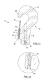
- FIG. 11 is a side cross-sectional view of the C-shaped hook according to FIG. 7 .
- FIG. 12 is a zoom view of a mounting portion of the flexible member of area XII of FIG. 11 .
- FIG. 13 is a bottom view of the C-shaped hook according to FIG. 7 .
- FIG. 14 is a perspective view of a C-shaped hook provided with an extension member according to another optional aspect of the present invention.
- FIG. 15 is a side view of the C-shaped hook provided with an extension member according to FIG. 14 .
- FIG. 16 is a perspective view of a C-shaped hook provided with a pair of extension members according to another optional aspect of the present invention.
- FIG. 17 is a side view of the C-shaped hook provided with a pair of extension members according FIG. 16 .
- FIG. 18 is a perspective view of a C-shaped hook according to another optional aspect of the present invention.
- FIG. 19 is a side view of the C-shaped hook according to FIG. 18 .
- FIG. 20 is a side view of a C-shaped hook provided according to another optional aspect of the present invention.
- FIG. 21 is a front view of a C-shaped hook according to an optional aspect of the present invention.
- FIG. 22 is a cross-sectional view of the C-shaped hook along line XXII of FIG. 21 .
- FIG. 23 is a perspective view of a C-shaped hook provided with an aligned extension member according to another optional aspect of the present invention.
- FIG. 24 is a cross-sectional view of the C-shaped hook of FIG. 23 .
- FIG. 25 is a perspective view of a C-shaped hook provided with an aligned extension member according to another optional aspect of the present invention.
- FIG. 26 is a cross-sectional view of the C-shaped hook of FIG. 25 .
- FIG. 27 is a perspective view of a C-shaped hook provided with an aligned extension member according to another optional aspect of the present invention.
- FIG. 28 is a cross-sectional view of the C-shaped hook of FIG. 27 .
- FIG. 29 is a perspective view of a C-shaped hook provided with an aligned extension member according to another optional aspect of the present invention.
- FIG. 30 is a cross-sectional view of the C-shaped hook of FIG. 29 .
- FIG. 31 is a perspective view of an underground strap provided at both end with a C-shaped hook according to another optional aspect of the present invention.
- FIG. 32 is a side view of the underground strap of FIG. 31 .
- the present invention relates to a hook including holding means which provide a solution for preventing the hook from unhooking from an underground tank anchor, and further include guiding means which facilitate the anchorage of the hook to the anchor.
- FIGS. 1 and 2 Prior Art
- the anchorage of an underground tank ( 2 ) is performed with at least one strap ( 4 ) which must be fixed to anchor blocks ( 6 ) on each side of the tank ( 2 ) in order to secure it.
- FIG. 1 shows two straps ( 4 ) surrounding a tank ( 2 ) and tightened together at the top the tank ( 2 ) with a binding assembly.
- FIG. 2 shows a single strap contacting and holding down the underground tank ( 2 ).
- the straps ( 4 ) are provided with a hook ( 8 ) on either end.
- the anchorage of the hook ( 8 ) to the anchor block ( 6 ) is a difficult operation because the main challenge is to keep the connection between the strap ( 4 ) and the anchor block ( 6 ) on one side of the tank ( 2 ) while connecting the strap ( 4 ) to another anchor block ( 6 ) on the other side of the tank ( 2 ), or to the binding assembly as in FIG. 1 .
- the operation is even more complex when the connection between the strap ( 4 ) and the anchor block ( 6 ) has to be performed from the top of the tank ( 2 ).
- the hooks ( 8 ) may escape the anchor ( 6 ).
- Hooks ( 8 ) may also be released from the anchor ( 6 ) during flood, earthquake, drought or any situation inducing movement of the ground.
- FIG. 3 illustrates a conventional anchor block ( 6 ) including a concrete block base ( 6 a ) holding an embedded anchor element as a rod ( 6 b ). The hook catches onto the embedded rod ( 6 b ).
- conventional straps ( 4 ) are provided with hooks ( 8 a , 8 b , 8 c ) at either end.
- these hooks may be classified under three categories which are C-shaped hooks ( 8 a ), D-shaped hooks ( 8 b ) and T-shaped hooks ( 8 c ). Hooks may be connected to each end of the strap ( 4 ).
- C and D-shaped hooks ( 8 a and 8 b ) are configured to engage anchor blocks ( 6 ) provided underground.
- D-shaped and T-shaped hooks ( 8 c ) may be provided to the end of the strap which is connected to the top of the tank as in the configuration illustrated in FIG. 1 .
- FIG. 4 illustrates a DC strap where the strap ( 4 ) is provided with a C-shaped hook ( 8 a ) at one end and a D-shaped hook ( 8 b ) at the other end.
- a strap ( 4 ) may also have a TC configuration with a C-shaped hook ( 8 a ) at one end and T-shaped hook ( 8 c ) at the other end as represented on FIG. 5 .
- the configurations of the straps are various and are not limited to the embodiments illustrated in the figures; for example, CC straps or DD straps are also possible configurations.
- a conventional C-shaped hook ( 8 a ) is represented in greater detail on FIG. 6 . Workers encounter difficulties to secure these conventional C-shaped hooks ( 8 a ) to the anchor block ( 6 ) since these hooks may easily escape from the anchor block ( 6 ) if the strap ( 4 ) is not tightly held.
- the present invention provides a hook ( 8 ) which differs from conventional hooks ( 8 a , 8 b , 8 c ) by including holding means for holding the anchor block ( 6 ) onto the hook ( 8 ).
- the hook ( 8 ) for attaching the hold down strap ( 4 ) to the anchor block ( 6 ), includes a main component ( 9 ) having a curved portion ( 10 ) defining a concave receiving area ( 11 ) for the anchor element ( 6 b ) of the anchor block ( 6 ), and a base portion ( 12 ) connectable to the hold down strap ( 4 ).
- the curved portion ( 10 ) extends from the base portion ( 12 ) and is optionally a generally C-shaped portion.
- the concave receiving area ( 11 ) includes an entrance which is sized and configured for receiving the anchor element ( 6 b ).
- the hook ( 8 ) also includes a flexible member ( 14 ) extending across the entrance of the concave receiving area ( 11 ) as holding means.
- the flexible member ( 14 ) is chemically fixed to the main component ( 9 ), optionally to the base portion ( 12 ) which defines a longitudinal axis generally aligned with the hold down strap ( 4 ).
- the flexible member ( 14 ) optionally extends from the base portion ( 12 ) in parallel relation to this longitudinal axis.
- the base portion ( 12 ) may include a slot ( 15 ) from which the flexible member ( 14 ) extends across the entrance of the concave receiving area ( 11 ) of the hook ( 8 ).
- the base portion ( 12 ) may include a protrusion ( 16 ) provided with the slot ( 15 ) and extending away from the base portion ( 12 ) with parallel relation to the longitudinal axis.
- FIG. 8 illustrates the hook ( 8 ) provided at one end of the hold down strap ( 4 ) and cast from an upper part of the underground tank down toward the anchor element ( 6 b ) of the anchor block.
- the flexible member ( 14 ) is sized and configured to bend from a closed position ( FIG. 8 ) to an open position ( FIG. 9 ).
- FIG. 8 illustrates the hook ( 8 ) provided at one end of the hold down strap ( 4 ) and cast from an upper part of the underground tank down toward the anchor element ( 6 b ) of the anchor block.
- the flexible member ( 14 ) is sized and configured to bend from a closed position ( FIG. 8 ) to an open position ( FIG. 9 ).
- FIG. 9 illustrates the bending of the flexible member ( 14 ) from its closed position to its open position while the anchor element ( 6 b ) traverses the entrance of the concave receiving area ( 11 ) thus allowing the anchor element ( 6 b ) to enter this area ( 11 ).
- the flexible member ( 14 ) moves back to its closed position in order to retain the anchor element ( 6 b ) within the concave receiving area ( 11 ), thereby securing the hook ( 8 ) to the anchor block.
- the other side of the hold down strap ( 4 ) may be attached more easily to another anchor block or to the binding assembly at the top of the tank ( FIG. 1 ).
- the flexible member ( 14 ) has a degree of flexibility enabling sufficient bending in response to casting of the hook ( 8 ) to allow the anchor element ( 6 b ) to enter into the concave receiving area ( 11 ).
- the degree of flexibility of the flexible member ( 14 ) also prevents sufficient bending allowing release of the anchor element ( 6 b ) from the concave receiving area ( 11 ) in response to slack on the hold down strap ( 4 ).
- the chemical fixing of the flexible member ( 14 ) to the main component ( 9 ) is obtained with a non-corroding adhesive ( 18 ) such as epoxy or similar strong adhesive.
- a non-corroding adhesive such as epoxy or similar strong adhesive.
- Thermoset resins, thermal glue, silicon oil-based or water-based glue are examples of suitable adhesives.
- Thermoset resins may be polyester, urethane, vinyl ester, acrylic, phenolic, or thermal glue.
- Thermal glue may be polypropylene or nylon.
- the flexible member ( 14 ) may include a mounting part ( 20 ) chemically fixed into the slot ( 15 ).
- the slot ( 15 ) optionally has a dove tail shape to enhance the strength of the connection with the mounting part ( 20 ).
- the mounting part ( 20 ) of the flexible member ( 14 ) may be chemically fixed with the above mentioned adhesive within the dove tail shaped slot ( 15 ) and may further include a surface with retention angles to enhance the connection.
- the hook ( 8 ) includes a strap slot ( 22 ) optionally having a dove tail shape for connecting the hold down strap ( 4 ) via a connecting insert ( 23 ) to the bottom of the base portion ( 12 ).
- the curved portion ( 10 ) has an end tip ( 24 ) from which the flexible member is optionally spaced away and arranged in opposed and aligned relation with it.
- the hook ( 8 ) may also include an extension member ( 26 ) extending from the curved portion ( 10 ) beyond the entrance of the concave receiving area ( 11 ).
- the extension member ( 26 ) is optionally configured in oblique relation to the flexible member ( 14 ).
- the extension member may be engaged into a slot ( 27 ) provided on a casing component ( 28 ) which is fitted to the end tip ( 24 ) of the curved portion ( 10 ) so as to hold the extension member ( 26 ) onto the hook ( 8 ).
- the extension member ( 26 ) may have a mounting portion chemically fixed into the slot ( 27 ), similar to the flexible member ( 14 ).
- the extension member ( 26 ) advantageously enables a guiding of the anchor element ( 6 b ) toward the entrance of the concave receiving area ( 11 ) as the hook ( 8 ) falls near the anchor element or when pulling the hook ( 8 ).
- the hook ( 8 ) may also include first and second extension members ( 26 a , 26 b ) extending from the end tip ( 24 ) of the curved portion ( 10 ) in opposed parallel relation to each other and beyond the entrance of the concave receiving area ( 11 ).
- the end tip ( 24 ) optionally includes first and second slots ( 27 a , 27 b ) provided on first and second protrusions ( 30 a , 30 b ) extending away from each opposite side of the end tip ( 24 ).
- the two protrusions ( 30 a , 30 b ) optionally include slots ( 27 a , 27 b ) with a dove tail shape.
- the extension members ( 26 a , 26 b ) may be chemically fixed in to the slots ( 27 a , 27 b ).
- an angle ( ⁇ ) between the flexible member ( 14 ) and the extension members ( 30 a , 30 b ) ranges from about 10° to about 60° and is more optionally about 45° C.
- This configuration of the ho ok ( 8 ) with two extension members ( 26 a and 26 b ) enhances the guiding of the hook and its stability, and limits the hook twisting.
- the hook ( 8 ) may also include first and second flexible members ( 14 a , 14 b ).
- the two flexible members ( 14 a , 14 b ) and the two extension members ( 26 a , 26 b ) are optionally arranged in a jaw-like configuration so as to catch and retain the anchor element.
- the first and second flexible members ( 14 a , 14 b ) optionally extend respectively from first and second slots ( 15 a , 15 b ) provided on first and second protrusions ( 16 a , 16 b ) on opposite sides of the base portion.
- the two flexible members ( 14 a , 14 b ) are laterally offset with respect to a central plane of the main component ( 9 ) and may also be laterally spaced away from the respective side surfaces of the main component ( 9 ).
- This configuration of the hook ( 8 ) with two flexible members ( 14 a and 14 b ) enhances the stability of the hooking and, as the first and second flexible members are spaced away from the main component ( 9 ), their deflection may be augmented to facilitate the hooking and reduce the stress on the extension member(s).
- each protrusion ( 16 a , 16 b , 30 a and 30 b ) may include a slot ( 16 a , 16 b , 17 a and 17 b ) having a dove tail shape which may be opened from a distal side of the protrusion.
- the respective flexible members ( 14 a , 14 b ) and extension members ( 26 a , 26 b ) are chemically fixed with non-corroding adhesive to the respective dove tail-shaped slot ( 16 a , 16 b , 17 a and 17 b ).
- the extension member may have a guiding surface aligned with an inner surface of the curved portion so as to define a substantially continuous and/or co-planar surface for facilitating the entrance of the anchor element into the concave receiving area.
- the extension member may be a one-piece structure or include several components. It should be understood that all the embodiments and aspects relating to the extension members ( 26 a , 26 b ) as illustrated in FIGS. 16 to 30 are also applicable to the extension member ( 26 ) as illustrated in FIGS. 14 and 15 .
- FIGS. 23 to 30 illustrate four possible configurations of the extension member ( 26 a , 26 b ) having a guiding surface ( 32 ) aligned with an inner surface ( 34 ) of the curved portion ( 10 ).
- the alignment of the guiding surface ( 32 ) and the inner surface ( 34 ) of the curved portion ( 10 ) may define a substantially continuous surface for allowing improved reliability and efficiency of hooking. Indeed, this substantially continuous surface enhances the sliding of the anchor element into the concave receiving area ( 11 ), while minimizing blockages that could occur when reaching the end tip ( 24 ) of the curved portion ( 10 ).
- the extension member ( 26 a , 26 b ) may include an elongated upper component ( 36 ) and a lower component ( 38 ), connected to the elongated upper component ( 36 ) and provided with the guiding surface ( 32 ).
- the lower component ( 38 ) may be shorter than the elongated upper component ( 36 ).
- the lower component ( 38 ) may be fixed to the elongated upper component ( 36 ), optionally chemically fixed to the elongated upper component ( 36 ).
- FIGS. 23 and 24 illustrate the lower component ( 38 ) having a rectangular shape, thereby defining a substantially rectangular-shaped extension member ( 26 a , 26 b ) having a guiding surface ( 32 ) substantially continuous to the inner surface ( 34 ) of the curved portion ( 10 ).
- FIGS. 25 and 26 illustrate the lower component ( 38 ) having a tapered distal end ( 39 ), thereby facilitating the sliding of the anchor element along the guiding surface ( 32 ) into the concave receiving area ( 11 ).
- the extension member ( 26 a , 26 b ) may further include an intermediate component ( 40 ) located between the elongated upper component ( 36 ) and the lower component ( 38 ).
- the intermediate component ( 40 ) may extend from a distal end of the elongated upper component ( 36 ) unto a middle region of the elongated upper component ( 36 ), such that the intermediate component ( 40 ) does not reach the end tip ( 24 ) of the curved portion ( 10 ).
- the lower component ( 38 ) may either extend along the upper elongated component ( 36 ) unto the end tip ( 24 ) of the curved portion ( 10 ) (as seen on FIGS. 23 , 24 , 27 and 28 ) or extend farther along each side of the curved portion ( 10 ) (as seen on FIGS. 25 , 26 , 29 and 30 ).
- the flexible member ( 14 ) may be composed of a pultruded material and may be a one-piece structure.
- the flexible member ( 16 ) and the extension member ( 26 ) may have a rod shape or an elongated tab shape.
- the possible materials of the flexible member ( 14 ) are pultruded materials including fiberglass, graphite, carbon fiber and sisal fiber joined with thermoset resin such as, polyester, epoxy, vinyl ester, phenolic and acrylic.
- the pultruded materials also include thermoplastic fibers such as polyester, nylon, polypropylene, polyethylene and other polyacetates.
- the possible materials of the extension member ( 26 ) include fiberglass, graphite, carbon fiber and sisal fiber joined with thermoset resin such as, polyester, epoxy, vinyl ester, phenolic and acrylic.
- the possible materials of the extension member(s) also include thermoplastic fibers such as polyester, nylon, polypropylene, polyethylene and or other polyacetates.
- the thickness of the flexible member ( 14 ) may range from about 1 mm to about 8 mm.
- the thickness of the extension member ( 26 ) may range from about 1 mm to about 8 mm.
- the angle of deflection of the flexible member ( 14 ) from its resting closed position may range between about 10° and about 70°.
- the main component ( 9 ) of the hook ( 8 ) may be a one-piece structure and be composed of cast iron covered with galvanized material.
- the extension member ( 26 ) may be molded onto the main component as a one-piece structure in cast iron covered with galvanized material.
- a hold-down strap including a strap ( 4 ) having two opposed ends and a hook ( 8 ) as previously described attached to at least one of the opposed ends.
- FIGS. 31 and 32 provide respective perspective and side views of a hold down strap according to the present invention having a hook ( 8 ), as illustrated on FIGS. 16 and 17 , at either opposite end of the strap ( 4 ).
- a method of holding down an underground tank includes four main steps which are providing a hold down strap ( 4 ) with a hook ( 8 ) as previously described; providing an underground tank ( 2 ) having an upper part; providing an anchor element ( 6 b ) proximate to the underground tank ( 2 ) and below the upper part of the tank ( 2 ); and casting the first end of the hold down strap ( 4 ) from the upper part of the tank ( 2 ) down toward the anchor element ( 6 b ), the casting including three main stages as previously described.
- the present invention is not limited to including a pair of extension members or a pair of flexible members, but may also include a plurality of extension and flexible members fixed and located on the main component similarly to the previously described embodiments.
Landscapes
- Engineering & Computer Science (AREA)
- General Engineering & Computer Science (AREA)
- Mechanical Engineering (AREA)
- Hooks, Suction Cups, And Attachment By Adhesive Means (AREA)
- Filling Or Discharging Of Gas Storage Vessels (AREA)
Priority Applications (1)
| Application Number | Priority Date | Filing Date | Title |
|---|---|---|---|
| US14/356,947 US9228606B2 (en) | 2011-11-08 | 2012-11-07 | Hook with holding means and method for holding down underground tank with a strap |
Applications Claiming Priority (3)
| Application Number | Priority Date | Filing Date | Title |
|---|---|---|---|
| US201161556966P | 2011-11-08 | 2011-11-08 | |
| US14/356,947 US9228606B2 (en) | 2011-11-08 | 2012-11-07 | Hook with holding means and method for holding down underground tank with a strap |
| PCT/CA2012/050791 WO2013067641A1 (fr) | 2011-11-08 | 2012-11-07 | Crochet doté d'un moyen de maintien et procédé de maintien de réservoir souterrain à l'aide d'une sangle |
Publications (2)
| Publication Number | Publication Date |
|---|---|
| US20140291471A1 US20140291471A1 (en) | 2014-10-02 |
| US9228606B2 true US9228606B2 (en) | 2016-01-05 |
Family
ID=48288412
Family Applications (1)
| Application Number | Title | Priority Date | Filing Date |
|---|---|---|---|
| US14/356,947 Active US9228606B2 (en) | 2011-11-08 | 2012-11-07 | Hook with holding means and method for holding down underground tank with a strap |
Country Status (3)
| Country | Link |
|---|---|
| US (1) | US9228606B2 (fr) |
| CA (1) | CA2854824C (fr) |
| WO (1) | WO2013067641A1 (fr) |
Cited By (3)
| Publication number | Priority date | Publication date | Assignee | Title |
|---|---|---|---|---|
| US20180187827A1 (en) * | 2014-03-27 | 2018-07-05 | Pultrusion Technique Inc. | Anchors and methods for anchoring an underground storage tank |
| US10563689B2 (en) | 2015-09-10 | 2020-02-18 | Easyclic Gmbh | Hook in conjunction with an element to be inserted into the hook interior |
| US10858222B1 (en) * | 2019-06-18 | 2020-12-08 | Christopher Laarman | Couplers with partially open gates |
Families Citing this family (4)
| Publication number | Priority date | Publication date | Assignee | Title |
|---|---|---|---|---|
| GB2524070B (en) * | 2014-03-13 | 2017-07-12 | Fast Eng Ltd | Suspension device |
| EP3362532B1 (fr) * | 2015-10-13 | 2022-08-10 | Pultrusion Technique Inc. | Techniques de fabrication et d'utilisation de sangles de maintien à fixation par crochet et sangle |
| USD839724S1 (en) * | 2017-10-23 | 2019-02-05 | Spectrum Brands, Inc. | Bungee cord adapter |
| EP4178882A4 (fr) * | 2020-07-10 | 2024-07-03 | Pultrusion Technique Inc. | Ensemble d'ancrage pour ancrer un réservoir souterrain |
Citations (6)
| Publication number | Priority date | Publication date | Assignee | Title |
|---|---|---|---|---|
| CA2257307A1 (fr) | 1996-06-26 | 1997-12-31 | Henry Norrby | Crochet de securite et plaque de blocage pour ce crochet |
| US5728787A (en) * | 1996-06-19 | 1998-03-17 | Dymax Corporation | Rapid curing, non-corroding adhesive composition, and method of use |
| US6059252A (en) | 1998-03-13 | 2000-05-09 | Daimlerchrysler Ag | Arrangement for mounting fuel tank to a motor vehicle |
| CA2457914A1 (fr) | 2004-02-16 | 2005-08-16 | Bob Claus | Mousqueton avec dispositif de fermeture ameliore |
| US7946005B2 (en) * | 2007-06-07 | 2011-05-24 | The New Haven Companies, Inc. | Safety hook |
| US20140102259A1 (en) * | 2012-10-16 | 2014-04-17 | Zachary Albrecht | Carabiner Bottle Opener |
-
2012
- 2012-11-07 CA CA2854824A patent/CA2854824C/fr active Active
- 2012-11-07 US US14/356,947 patent/US9228606B2/en active Active
- 2012-11-07 WO PCT/CA2012/050791 patent/WO2013067641A1/fr not_active Ceased
Patent Citations (6)
| Publication number | Priority date | Publication date | Assignee | Title |
|---|---|---|---|---|
| US5728787A (en) * | 1996-06-19 | 1998-03-17 | Dymax Corporation | Rapid curing, non-corroding adhesive composition, and method of use |
| CA2257307A1 (fr) | 1996-06-26 | 1997-12-31 | Henry Norrby | Crochet de securite et plaque de blocage pour ce crochet |
| US6059252A (en) | 1998-03-13 | 2000-05-09 | Daimlerchrysler Ag | Arrangement for mounting fuel tank to a motor vehicle |
| CA2457914A1 (fr) | 2004-02-16 | 2005-08-16 | Bob Claus | Mousqueton avec dispositif de fermeture ameliore |
| US7946005B2 (en) * | 2007-06-07 | 2011-05-24 | The New Haven Companies, Inc. | Safety hook |
| US20140102259A1 (en) * | 2012-10-16 | 2014-04-17 | Zachary Albrecht | Carabiner Bottle Opener |
Cited By (6)
| Publication number | Priority date | Publication date | Assignee | Title |
|---|---|---|---|---|
| US20180187827A1 (en) * | 2014-03-27 | 2018-07-05 | Pultrusion Technique Inc. | Anchors and methods for anchoring an underground storage tank |
| US10533701B2 (en) * | 2014-03-27 | 2020-01-14 | Pultrusion Technique Inc. | Anchors and methods for anchoring an underground storage tank |
| US20200103072A1 (en) * | 2014-03-27 | 2020-04-02 | Pultrusion Technique Inc. | Anchors and methods for anchoring an underground storage tank |
| US10781968B2 (en) * | 2014-03-27 | 2020-09-22 | Pultrusion Technique Inc. | Anchors and methods for anchoring an underground storage tank |
| US10563689B2 (en) | 2015-09-10 | 2020-02-18 | Easyclic Gmbh | Hook in conjunction with an element to be inserted into the hook interior |
| US10858222B1 (en) * | 2019-06-18 | 2020-12-08 | Christopher Laarman | Couplers with partially open gates |
Also Published As
| Publication number | Publication date |
|---|---|
| CA2854824A1 (fr) | 2013-05-16 |
| US20140291471A1 (en) | 2014-10-02 |
| WO2013067641A1 (fr) | 2013-05-16 |
| CA2854824C (fr) | 2019-06-04 |
Similar Documents
| Publication | Publication Date | Title |
|---|---|---|
| US9228606B2 (en) | Hook with holding means and method for holding down underground tank with a strap | |
| US6978973B1 (en) | Pipe or cable clamp | |
| US8015676B1 (en) | Snap hook with interlocking gate | |
| RU2008118153A (ru) | Узел трубопровода, содержащий якорное устройство, и способ его установки | |
| KR20050063634A (ko) | 적층가능한 옹벽 유닛을 위한 강화 시스템 | |
| RU2582689C2 (ru) | Устройство стабилизации грунта | |
| RU2528472C2 (ru) | Хомут для закрепления труб или проводящих линий | |
| US8919704B2 (en) | Conduit hanger and support apparatus | |
| JP5806833B2 (ja) | 架空線の防鳥用細線の間隔保持材 | |
| US8121466B2 (en) | Deicer anchoring system | |
| US10508447B2 (en) | Sealing cover for concrete anchor | |
| US20130193301A1 (en) | Solar panel attachment system for a roof | |
| BR112016030295A2 (pt) | Ancoramento de risers flexíveis submarinos | |
| US11684055B2 (en) | Universal clamp for securing an object to a fishing line | |
| US10649169B2 (en) | Sliding jaw drop clamp | |
| US20100329792A1 (en) | Controlled bending of pipeline by external force | |
| US8940160B2 (en) | Recessed restrictor plate | |
| US8092119B2 (en) | Pipeline buoyancy control assembly and tiedown | |
| JP5642743B2 (ja) | 分水口ゲート | |
| US7984534B2 (en) | Cable restraint clip | |
| EP0048307A1 (fr) | Procédé et dispositif de pose d'un conduit de tuyaux et conduit de tuyau posé à l'aide de ce procédé | |
| CA2589507A1 (fr) | Support intermediaire pour des cables d'arret de chute/filins de securite | |
| CN101023279A (zh) | 钢筋连接夹具以及用于固定钢筋的系统 | |
| US20190330816A1 (en) | Installation Guide with Quick Release and a Method Thereof | |
| US12270176B2 (en) | Anchor system |
Legal Events
| Date | Code | Title | Description |
|---|---|---|---|
| AS | Assignment |
Owner name: PULTRUSION TECHNIQUE INC., CANADA Free format text: ASSIGNMENT OF ASSIGNORS INTEREST;ASSIGNOR:DUFRESNE, ROBERT P.;REEL/FRAME:033118/0050 Effective date: 20121113 |
|
| STCF | Information on status: patent grant |
Free format text: PATENTED CASE |
|
| MAFP | Maintenance fee payment |
Free format text: PAYMENT OF MAINTENANCE FEE, 4TH YR, SMALL ENTITY (ORIGINAL EVENT CODE: M2551); ENTITY STATUS OF PATENT OWNER: SMALL ENTITY Year of fee payment: 4 |
|
| MAFP | Maintenance fee payment |
Free format text: PAYMENT OF MAINTENANCE FEE, 8TH YR, SMALL ENTITY (ORIGINAL EVENT CODE: M2552); ENTITY STATUS OF PATENT OWNER: SMALL ENTITY Year of fee payment: 8 |