US9228663B2 - Diverter valve device, in particular for a washing machine, such as a dishwasher - Google Patents
Diverter valve device, in particular for a washing machine, such as a dishwasher Download PDFInfo
- Publication number
- US9228663B2 US9228663B2 US14/026,800 US201314026800A US9228663B2 US 9228663 B2 US9228663 B2 US 9228663B2 US 201314026800 A US201314026800 A US 201314026800A US 9228663 B2 US9228663 B2 US 9228663B2
- Authority
- US
- United States
- Prior art keywords
- plug
- outlets
- chamber
- operating condition
- valve seat
- Prior art date
- Legal status (The legal status is an assumption and is not a legal conclusion. Google has not performed a legal analysis and makes no representation as to the accuracy of the status listed.)
- Expired - Fee Related, expires
Links
Images


Classifications
-
- F—MECHANICAL ENGINEERING; LIGHTING; HEATING; WEAPONS; BLASTING
- F16—ENGINEERING ELEMENTS AND UNITS; GENERAL MEASURES FOR PRODUCING AND MAINTAINING EFFECTIVE FUNCTIONING OF MACHINES OR INSTALLATIONS; THERMAL INSULATION IN GENERAL
- F16K—VALVES; TAPS; COCKS; ACTUATING-FLOATS; DEVICES FOR VENTING OR AERATING
- F16K11/00—Multiple-way valves, e.g. mixing valves; Pipe fittings incorporating such valves
- F16K11/02—Multiple-way valves, e.g. mixing valves; Pipe fittings incorporating such valves with all movable sealing faces moving as one unit
- F16K11/06—Multiple-way valves, e.g. mixing valves; Pipe fittings incorporating such valves with all movable sealing faces moving as one unit comprising only sliding valves, i.e. sliding closure elements
- F16K11/065—Multiple-way valves, e.g. mixing valves; Pipe fittings incorporating such valves with all movable sealing faces moving as one unit comprising only sliding valves, i.e. sliding closure elements with linearly sliding closure members
- F16K11/07—Multiple-way valves, e.g. mixing valves; Pipe fittings incorporating such valves with all movable sealing faces moving as one unit comprising only sliding valves, i.e. sliding closure elements with linearly sliding closure members with cylindrical slides
-
- A—HUMAN NECESSITIES
- A47—FURNITURE; DOMESTIC ARTICLES OR APPLIANCES; COFFEE MILLS; SPICE MILLS; SUCTION CLEANERS IN GENERAL
- A47L—DOMESTIC WASHING OR CLEANING; SUCTION CLEANERS IN GENERAL
- A47L15/00—Washing or rinsing machines for crockery or tableware
- A47L15/14—Washing or rinsing machines for crockery or tableware with stationary crockery baskets and spraying devices within the cleaning chamber
- A47L15/18—Washing or rinsing machines for crockery or tableware with stationary crockery baskets and spraying devices within the cleaning chamber with movably-mounted spraying devices
- A47L15/22—Rotary spraying devices
-
- A—HUMAN NECESSITIES
- A47—FURNITURE; DOMESTIC ARTICLES OR APPLIANCES; COFFEE MILLS; SPICE MILLS; SUCTION CLEANERS IN GENERAL
- A47L—DOMESTIC WASHING OR CLEANING; SUCTION CLEANERS IN GENERAL
- A47L15/00—Washing or rinsing machines for crockery or tableware
- A47L15/42—Details
- A47L15/4214—Water supply, recirculation or discharge arrangements; Devices therefor
- A47L15/4219—Water recirculation
- A47L15/4221—Arrangements for redirection of washing water, e.g. water diverters to selectively supply the spray arms
-
- F—MECHANICAL ENGINEERING; LIGHTING; HEATING; WEAPONS; BLASTING
- F16—ENGINEERING ELEMENTS AND UNITS; GENERAL MEASURES FOR PRODUCING AND MAINTAINING EFFECTIVE FUNCTIONING OF MACHINES OR INSTALLATIONS; THERMAL INSULATION IN GENERAL
- F16K—VALVES; TAPS; COCKS; ACTUATING-FLOATS; DEVICES FOR VENTING OR AERATING
- F16K11/00—Multiple-way valves, e.g. mixing valves; Pipe fittings incorporating such valves
- F16K11/02—Multiple-way valves, e.g. mixing valves; Pipe fittings incorporating such valves with all movable sealing faces moving as one unit
- F16K11/06—Multiple-way valves, e.g. mixing valves; Pipe fittings incorporating such valves with all movable sealing faces moving as one unit comprising only sliding valves, i.e. sliding closure elements
- F16K11/072—Multiple-way valves, e.g. mixing valves; Pipe fittings incorporating such valves with all movable sealing faces moving as one unit comprising only sliding valves, i.e. sliding closure elements with pivoted closure members
-
- F—MECHANICAL ENGINEERING; LIGHTING; HEATING; WEAPONS; BLASTING
- F16—ENGINEERING ELEMENTS AND UNITS; GENERAL MEASURES FOR PRODUCING AND MAINTAINING EFFECTIVE FUNCTIONING OF MACHINES OR INSTALLATIONS; THERMAL INSULATION IN GENERAL
- F16K—VALVES; TAPS; COCKS; ACTUATING-FLOATS; DEVICES FOR VENTING OR AERATING
- F16K31/00—Actuating devices; Operating means; Releasing devices
- F16K31/44—Mechanical actuating means
-
- Y—GENERAL TAGGING OF NEW TECHNOLOGICAL DEVELOPMENTS; GENERAL TAGGING OF CROSS-SECTIONAL TECHNOLOGIES SPANNING OVER SEVERAL SECTIONS OF THE IPC; TECHNICAL SUBJECTS COVERED BY FORMER USPC CROSS-REFERENCE ART COLLECTIONS [XRACs] AND DIGESTS
- Y10—TECHNICAL SUBJECTS COVERED BY FORMER USPC
- Y10T—TECHNICAL SUBJECTS COVERED BY FORMER US CLASSIFICATION
- Y10T137/00—Fluid handling
- Y10T137/8593—Systems
- Y10T137/86493—Multi-way valve unit
- Y10T137/86863—Rotary valve unit
- Y10T137/86871—Plug
Definitions
- the present invention is relative to a diverter valve device, in particular for a washing machine, such as a dishwasher.
- the present invention is relative to a device that acts as a flow diverter, able to divide a fluid flow entering through at least one inlet leading to the device itself, thus distributing it among a plurality of outlets by means of the actuation of a plug organ, which obstructs and frees the outlets according to predetermined criteria.
- a device of the type described above is used in the field of household appliances in order to selectively direct a fluid flow coming from an inlet towards a first outlet and a second outlet.
- this type of device is often used as an alternate washing unit in dishwashers, since it allows a washing liquid flow coming from a supply apparatus (for example a hydraulic pump) to be selectively diverted towards a first outlet, which can be connected to an upper impeller that is suited to deliver the washing liquid to dishes arranged in an upper rack of the machine, and towards a second outlet, which can be connected to a lower impeller that is suited to deliver the washing liquid to dishes arranged in a lower rack of the machine.
- the plug is generally moved by means of actuator means, which, based on predetermined criteria, cause it to alternately obstruct the first outlet and the second outlet.
- the present invention is relative to a diverter valve device, namely a diverter valve device comprising:
- the object of the present invention is to provide a diverter valve device, which is able to solve the drawbacks of the prior art and, in particular, can be manufactured in a simple and economic fashion.
- a diverter valve device having the features set forth in the appended independent claim and, in particular, characterized in that said body has, furthermore, a substantially axial valve seat and a substantially radial valve seat, which are fluidly arranged between said chamber and one of said outlets and the other one of said outlets, respectively; said plug being suited to assume at least a first and a second operating condition, in which it respectively frees and obstructs said substantially axial valve seat as well as respectively obstructs and frees said substantially radial valve seat.
- FIGS. 1 and 2 respectively are a prospective view and a plan view from the top of a diverter valve device manufactured according to an explanatory embodiment of the present invention
- FIG. 3 is a cross-section view according to line III-III of FIG. 2 ;
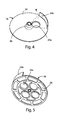
- FIGS. 4 and 5 respectively are a prospective view from the top and a prospective view from the bottom of a plug provided by the valve device shown in the previous figures;
- FIG. 6 is a cross-section view of the device shown in the previous figures, which is assembled in the sump of a dishwasher and is mechanically connected to a lower impeller of said machine.
- number 10 indicates, as a whole, a diverter valve device manufactured according to a preferred embodiment of the present invention.
- axial and radial as well as the expressions deriving therefrom refer to the axis indicated with X-X in FIG. 3 , so as to identify directions and orientations taken on by elements and components of device 10 .
- device 10 is adapted to be used in a washing machine, such as a dishwasher.
- device 10 comprises:
- Body 12 has, furthermore, a substantially axial valve seat 22 a and a substantially radial valve seat 22 b , which are fluidly arranged between chamber 14 and one outlet 20 a and the other outlet 20 b , respectively.
- Plug 16 is suited to assume a first operating condition (shown in FIG. 3 ) and a second operating condition, in which it respectively frees and obstructs the substantially axial seat 22 a as well as respectively obstructs and frees the substantially radial seat 22 b.
- the structure of device 10 is particularly reliable and takes up a small place.
- body 12 comprises a first portion, for example a hollow cup-shaped half-shell 12 a , which is coupled in a fluid-tight manner to a second portion, for example a lid 12 b , said cavity 14 being defined between the two portions.
- inlet 18 leads into chamber 14 in a substantially tangential direction, in particular laterally through the first portion or half-shell 12 a.
- outlets 20 a , 20 b stem from the bottom of the first portion or half-shell 12 a .
- outlets 20 a , 20 b both lie on the same side relative to said rotation axis X-X.
- outlet 20 a is arranged in a radially inner position
- outlet 20 b is arranged in a radially outer position relative to rotation axis X-X.
- the axes of outlets 20 a , 20 b are substantially parallel to one another and, more preferably, even relative to rotation axis X-X.
- the axes of outlets 20 a , 20 b can also be oriented in a different fashion, for example they can be slightly divergent from one another and, if necessary, even relative to rotation axis X-X.
- the first outlet 20 a can be fluidly connected to a first user circuit, for example the hydraulic circuit used to supply a pressurized liquid flow to an upper washing impeller of a dishwasher.
- the second outlet 20 b can be fluidly connected to a second user circuit, for example the hydraulic circuit used to supply a pressurized liquid flow to the lower washing impeller (indicated with number 34 in FIG. 6 ).
- device 10 comprises, furthermore, actuator means 23 , adapted to control the rotation of plug 16 between said operating conditions based on predetermined criteria.
- actuator means 23 comprise a known electric motor (not numbered) and, preferably, a reduction gear assembly (not numbered), for example a known gear, which cooperates with the electric motor and is adapted to control the rotation of plug 16 .
- actuator means 23 are housed in a cartridge or casing, which is mounted and housed through said lid 12 b .
- actuator means 23 comprise, furthermore, a reduction gear assembly (not numbered), such as a gear, which is operated by said electric motor and controls the rotation of actuator 16 .
- the electric motor is of the so-called brushless type.
- plug 16 preferably comprises an obstructing portion 24 , which has projecting part 24 b , which substantially projects in an axial direction and is adapted to close and free said substantially radial seat 22 b , when plug 16 respectively is in the first operating condition ( FIG. 3 ) and in the second operating condition.
- projecting part 24 b is peripherally supported by obstructing portion 24 .
- said projecting part 24 b defines a curved wall, which is supported by obstructing portion 24 and is adapted to be arranged on top of the substantially radial seat 22 b , when the plug is in the first operating condition.
- obstructing portion 24 has a substantially axial opening 24 a , which is eccentric relative to rotation axis X-X and is adapted to free the substantially axial seat 22 a , when plug 16 is in the first operating condition.
- opening 24 a is misaligned relative to the substantially axial seat 22 a , so that a solid region of obstructing portion 24 faces and obstructs the substantially axial seat 22 a , thus preventing fluid from flowing through it.
- opening 24 a is arranged on obstructing portion 24 in a position that is angularly delimited by projecting part 24 b .
- opening 24 a is substantially comprised in circular sector ⁇ defined by projecting part 24 b on obstructing portion 24 (to this regard, for the sake of clarity, see the dash-dot lines in FIG. 4 ).
- opening 24 a has a substantially circular cross-section.
- the substantially axial valve seat 22 a is made of a hole having a shape that substantially matches opening 24 a .
- this hole leads into the first outlet 20 a , which, in turn, has a cross-section that substantially matches that of the hole.
- obstructing portion 24 substantially has the shape of a plate, in particular a disc-shaped plate, for example with a substantially circular shape.
- plug 16 comprises a hub portion 26 , around which obstructing portion 24 radially develops and which is mechanically associated with actuator means 23 , preferably through the reduction gear assembly.
- hub portion 26 is splined to a shaft or rod 28 , which is supported, so as to rotate, by body 12 , in particular by the second portion or lid 12 b , and is controlled, during the rotation, by actuator means 23 , in particular through the reduction gear assembly.
- actuator means 23 are separated, in a fluid-tight manner, from chamber 14 by an intermediated shaped partition 29 , which is arranged on—and is crossed by—shaft or rod 28 and is suitably mounted in body 12 .
- partition 29 is locked in a fluid-tight manner, in correspondence to its periphery, between the mouth of the first portion or half-shell 12 a and the second portion or lid 12 b.
- a sealing gasket (not numbered) is interposed in an annular manner between partition 29 and the distal end of shaft or rod 28 .
- the distal end of shaft or rod 28 extends, with a finger shape, through chamber 14 and is splined to hub portion 26 of plug 16 .
- partition 29 is shaped so as to provide a dome formation 29 a , through which shaft or rod 28 is mounted so as to be guided during the rotation.
- the sealing gasket mentioned above is arranged between the top of dome formation 29 a and the distal end of shaft or rod 28 .
- a tubular body 29 b is defined within dome formation 29 a , said tubular body 29 b being run through by shaft or rod 28 , which is housed therein a guided during the rotation.
- shaft or rod 28 is adapted to rotate around rotation axis X-X, concentrically with plug 16 .
- device 10 comprises, furthermore, transmission means 30 , which cooperate with actuator means 23 , in particular with said reduction gear assembly, and are adapted to axially transfer a mechanical power through the second outlet 20 b in a substantially axial direction.
- the transmission means comprise a shaft or rod 32 , which is supported, so as to rotate, by body 12 , in particular by the second portion or lid 12 b , and is controlled, during the rotation, by actuator means 23 , in particular through the reduction gear assembly.
- shaft or rod 32 projects through the second outlet 20 b and is adapted to transmit a torque to the outside of device 10 .
- shaft or rod 32 can rotate around a rotation axis Y-Y (shown in FIG. 3 ), which is substantially parallel to rotation axis X-X of shaft or rod 28 associated with plug 16 .
- shaft or rod 32 can preferably be constrained, so as to rotate, to an impeller 34 , which is mounted in a dishwasher with freedom to rotate, for example in correspondence to sump P.
- This assembly allows the rotation of impeller 34 to be controlled through the same actuator means 23 that control the rotation of plug 16 between the different operating conditions.
- the second outlet 20 b is hydraulically connected to impeller 34 , so as to deliver to the latter the above-mentioned fluid flow, when plug 16 is in the second operating condition; at the same time, impeller 34 is constrained, during its rotation, to actuator means 23 through shaft or rod 32 , which control its rotation in the tank or washing chamber obtained in the dishwasher.
- shaft or rod 32 is housed, with freedom to rotate and in a fluid-tight fashion, in a tubular section 36 supported by half-shell 12 a .
- a further sealing gasket (not numbered) is interposed in an annular manner between tubular section 36 and the distal portion of shaft or rod 30 .
- tubular section 36 leads to the second outlet 20 b , for example in a substantially axial direction.
- tubular section 36 when mounted—extends through partition 29 , for example in a region thereof that is far from dome formation 29 a .
- another sealing gasket (not numbered) is interposed in an annular manner in the portion in which tubular section 36 extends through partition 29 .
- the substantially radial seat 22 b is obtained laterally through said tubular section 36 .
- the substantially radial seat 22 b consists of a lateral recess of tubular section 36 supported by body 12 , for example by the first portion or half-shell 12 a .
- the substantially radial seat 22 b has a substantially curved shape that is complementary to projecting part 24 that is adapted to obstruct and free it.
- shaft or rod 32 extends through axial tubular section 36 and the second outlet 20 b , so as not to interfere with the inflow of pressurized fluid controlled by the cooperation of plug 16 , in particular of projecting part 24 b , with the substantially radial seat 22 b.
- device 10 is mechanically fixed to sump P of the dishwasher, for example by connecting sump P to body 12 in a known manner.
- the plug can offer further operating configurations other than the ones shown.
- the plug can have further opening and/or closing projections in different angular positions on the obstructing portion; these further opening and/or closing projections can have shapes that, when they face the respective valve seats, allow them to choke the fluid flow through the outlets.
- This allows the valve seats to have configurations that are not limited to the ones of the “completely open” or completely closed” type, thus allowing the device to work in a flexible fashion and to adjust to different operating conditions.
Landscapes
- Engineering & Computer Science (AREA)
- General Engineering & Computer Science (AREA)
- Mechanical Engineering (AREA)
- Water Supply & Treatment (AREA)
- Multiple-Way Valves (AREA)
- Lift Valve (AREA)
- Detail Structures Of Washing Machines And Dryers (AREA)
- Control Of Washing Machine And Dryer (AREA)
Applications Claiming Priority (3)
| Application Number | Priority Date | Filing Date | Title |
|---|---|---|---|
| ITTO2012A000793 | 2012-09-14 | ||
| IT000793A ITTO20120793A1 (it) | 2012-09-14 | 2012-09-14 | Dispositivo valvolare di deviazione, in particolare per una macchina lavatrice, quale una lavastoviglie |
| ITTO2012A0793 | 2012-09-14 |
Publications (2)
| Publication Number | Publication Date |
|---|---|
| US20140076439A1 US20140076439A1 (en) | 2014-03-20 |
| US9228663B2 true US9228663B2 (en) | 2016-01-05 |
Family
ID=47146547
Family Applications (1)
| Application Number | Title | Priority Date | Filing Date |
|---|---|---|---|
| US14/026,800 Expired - Fee Related US9228663B2 (en) | 2012-09-14 | 2013-09-13 | Diverter valve device, in particular for a washing machine, such as a dishwasher |
Country Status (5)
| Country | Link |
|---|---|
| US (1) | US9228663B2 (pl) |
| EP (1) | EP2708178B1 (pl) |
| ES (1) | ES2543601T3 (pl) |
| IT (1) | ITTO20120793A1 (pl) |
| PL (1) | PL2708178T3 (pl) |
Cited By (2)
| Publication number | Priority date | Publication date | Assignee | Title |
|---|---|---|---|---|
| US10405727B2 (en) | 2017-06-20 | 2019-09-10 | Haier Us Appliance Solutions, Inc. | Disk diverter assembly for a dishwasher appliance |
| US11147430B2 (en) | 2019-03-27 | 2021-10-19 | Midea Group Co., Ltd. | Dishwasher including rack corner sprayers |
Families Citing this family (3)
| Publication number | Priority date | Publication date | Assignee | Title |
|---|---|---|---|---|
| US10113654B2 (en) * | 2015-01-27 | 2018-10-30 | Haier Us Appliance Solutions, Inc. | Water diverter assembly for a dishwashing appliance |
| US10010235B2 (en) | 2015-12-17 | 2018-07-03 | Whirlpool Corporation | Dish treating appliance with diverter valve position sensing |
| CN114688311B (zh) * | 2020-12-31 | 2025-09-09 | 宁波方太厨具有限公司 | 一种分水阀及应用有该分水阀的清洗机 |
Citations (10)
| Publication number | Priority date | Publication date | Assignee | Title |
|---|---|---|---|---|
| EP1050263A2 (en) | 1999-05-03 | 2000-11-08 | Electrolux Zanussi S.p.A. | Dishwashing machine with epicycloidal spray apparatus |
| EP1090579A1 (en) | 1999-10-01 | 2001-04-11 | SMEG S.p.A. | Revolving sprinkling assembly for dishwasher provided with a device for horizontal shift |
| EP1264570A1 (en) | 2000-02-14 | 2002-12-11 | Matsushita Electric Industrial Co., Ltd. | Washing machine |
| EP1502535A2 (en) | 2003-07-31 | 2005-02-02 | LG Electronics Inc. | Apparatus for controlling washing flow of dishwasher |
| US7047986B2 (en) * | 2001-12-21 | 2006-05-23 | Bsh Bosch Und Siemens Hausgeraete Gmbh | Movement reversal device, particularly for a dishwasher |
| US7100623B2 (en) * | 2001-07-07 | 2006-09-05 | Miele & Cie. Kg | Dishwasher having spray arms and a circulation pump |
| US7225488B2 (en) * | 2001-03-26 | 2007-06-05 | Sunflower Medical, L.L.C. | Air mattress control unit |
| EP2283764A2 (de) | 2009-08-11 | 2011-02-16 | BSH Bosch und Siemens Hausgeräte GmbH | Geschirrspülmaschine mit einer Wasserflusssteuereinrichtung |
| US20120097200A1 (en) | 2010-10-21 | 2012-04-26 | Whirlpool Corporation | Dishwasher with controlled rotation of lower spray arm |
| US8282741B2 (en) * | 2008-08-19 | 2012-10-09 | Whirlpool Corporation | Sequencing spray arm assembly for a dishwasher |
-
2012
- 2012-09-14 IT IT000793A patent/ITTO20120793A1/it unknown
-
2013
- 2013-09-13 PL PL13184404T patent/PL2708178T3/pl unknown
- 2013-09-13 ES ES13184404.5T patent/ES2543601T3/es active Active
- 2013-09-13 EP EP20130184404 patent/EP2708178B1/en active Active
- 2013-09-13 US US14/026,800 patent/US9228663B2/en not_active Expired - Fee Related
Patent Citations (11)
| Publication number | Priority date | Publication date | Assignee | Title |
|---|---|---|---|---|
| EP1050263A2 (en) | 1999-05-03 | 2000-11-08 | Electrolux Zanussi S.p.A. | Dishwashing machine with epicycloidal spray apparatus |
| EP1090579A1 (en) | 1999-10-01 | 2001-04-11 | SMEG S.p.A. | Revolving sprinkling assembly for dishwasher provided with a device for horizontal shift |
| EP1264570A1 (en) | 2000-02-14 | 2002-12-11 | Matsushita Electric Industrial Co., Ltd. | Washing machine |
| US7225488B2 (en) * | 2001-03-26 | 2007-06-05 | Sunflower Medical, L.L.C. | Air mattress control unit |
| US7100623B2 (en) * | 2001-07-07 | 2006-09-05 | Miele & Cie. Kg | Dishwasher having spray arms and a circulation pump |
| US7047986B2 (en) * | 2001-12-21 | 2006-05-23 | Bsh Bosch Und Siemens Hausgeraete Gmbh | Movement reversal device, particularly for a dishwasher |
| EP1502535A2 (en) | 2003-07-31 | 2005-02-02 | LG Electronics Inc. | Apparatus for controlling washing flow of dishwasher |
| US7614408B2 (en) * | 2003-07-31 | 2009-11-10 | Lg Electronics Inc. | Apparatus for controlling washing flow of dishwasher |
| US8282741B2 (en) * | 2008-08-19 | 2012-10-09 | Whirlpool Corporation | Sequencing spray arm assembly for a dishwasher |
| EP2283764A2 (de) | 2009-08-11 | 2011-02-16 | BSH Bosch und Siemens Hausgeräte GmbH | Geschirrspülmaschine mit einer Wasserflusssteuereinrichtung |
| US20120097200A1 (en) | 2010-10-21 | 2012-04-26 | Whirlpool Corporation | Dishwasher with controlled rotation of lower spray arm |
Non-Patent Citations (1)
| Title |
|---|
| Italian Search Report for IT Application No. 201220793 mailed Jun. 14, 2013 (8 pages). |
Cited By (2)
| Publication number | Priority date | Publication date | Assignee | Title |
|---|---|---|---|---|
| US10405727B2 (en) | 2017-06-20 | 2019-09-10 | Haier Us Appliance Solutions, Inc. | Disk diverter assembly for a dishwasher appliance |
| US11147430B2 (en) | 2019-03-27 | 2021-10-19 | Midea Group Co., Ltd. | Dishwasher including rack corner sprayers |
Also Published As
| Publication number | Publication date |
|---|---|
| EP2708178A1 (en) | 2014-03-19 |
| US20140076439A1 (en) | 2014-03-20 |
| PL2708178T3 (pl) | 2016-01-29 |
| ES2543601T3 (es) | 2015-08-20 |
| EP2708178B1 (en) | 2015-03-25 |
| ITTO20120793A1 (it) | 2014-03-15 |
Similar Documents
| Publication | Publication Date | Title |
|---|---|---|
| US9228663B2 (en) | Diverter valve device, in particular for a washing machine, such as a dishwasher | |
| AU2020200194B2 (en) | Pump and dishwasher comprising the same | |
| US10823175B2 (en) | Pump assembly and hydraulic system | |
| CN106321898A (zh) | 一种分水阀组件及洗碗机 | |
| KR101167956B1 (ko) | 냉매 제어용 전자밸브 | |
| JP2011047426A5 (pl) | ||
| JP2012067833A (ja) | 多方切換弁 | |
| US11073161B2 (en) | Centrifugal pump assembly | |
| CN107567546A (zh) | 具有多个可调整的排出开口的泵 | |
| US9933089B2 (en) | Decompression insert for rotary valve and rotary valve provided with such an insert | |
| WO2008089235A3 (en) | Faucet valve with safety handle | |
| CN108138800A (zh) | 泵机组和液压系统 | |
| JP2015148288A (ja) | 弁装置 | |
| EP3521701B1 (en) | Gas cock with a safety valve for a gas cooking appliance, and gas cooking appliance incorporating said gas cock | |
| KR20190065146A (ko) | 임펠러 펌프 | |
| JP2011001762A (ja) | シングルレバー混合水栓 | |
| US20140151281A1 (en) | Flow diverter device | |
| US8783288B2 (en) | Sidespray having volume control | |
| US9770155B2 (en) | Component for feeding a pressurized liquid to a washing tub of a washing machine, in particular a dishwasher | |
| KR100420589B1 (ko) | 수도콕 | |
| CN222848726U (zh) | 分水阀组件及洗碗机 | |
| CN205712386U (zh) | 一种用于电子坐便器的喷杆装置 | |
| JP2013174313A (ja) | 浄水用の水栓 | |
| KR20180075776A (ko) | 발전부재를 포함하는 세탁기용 급수밸브 | |
| WO2016088011A1 (en) | Valve device, in particular a diverter valve for a fluid flow for being used in a household appliance, for example a washing machine |
Legal Events
| Date | Code | Title | Description |
|---|---|---|---|
| ZAAA | Notice of allowance and fees due |
Free format text: ORIGINAL CODE: NOA |
|
| ZAAB | Notice of allowance mailed |
Free format text: ORIGINAL CODE: MN/=. |
|
| AS | Assignment |
Owner name: ELBI INTERNATIONAL SPA, ITALY Free format text: ASSIGNMENT OF ASSIGNORS INTEREST;ASSIGNORS:BRIGNONE, ENZO;RAVEDATI, PAOLO;GIORDANO, GIOVANNI;AND OTHERS;REEL/FRAME:037143/0444 Effective date: 20151015 |
|
| STCF | Information on status: patent grant |
Free format text: PATENTED CASE |
|
| MAFP | Maintenance fee payment |
Free format text: PAYMENT OF MAINTENANCE FEE, 4TH YEAR, LARGE ENTITY (ORIGINAL EVENT CODE: M1551); ENTITY STATUS OF PATENT OWNER: LARGE ENTITY Year of fee payment: 4 |
|
| FEPP | Fee payment procedure |
Free format text: MAINTENANCE FEE REMINDER MAILED (ORIGINAL EVENT CODE: REM.); ENTITY STATUS OF PATENT OWNER: LARGE ENTITY |
|
| LAPS | Lapse for failure to pay maintenance fees |
Free format text: PATENT EXPIRED FOR FAILURE TO PAY MAINTENANCE FEES (ORIGINAL EVENT CODE: EXP.); ENTITY STATUS OF PATENT OWNER: LARGE ENTITY |
|
| STCH | Information on status: patent discontinuation |
Free format text: PATENT EXPIRED DUE TO NONPAYMENT OF MAINTENANCE FEES UNDER 37 CFR 1.362 |
|
| FP | Lapsed due to failure to pay maintenance fee |
Effective date: 20240105 |