US9229237B2 - Helmet mounted display system adjustable for bright ambient light conditions - Google Patents
Helmet mounted display system adjustable for bright ambient light conditions Download PDFInfo
- Publication number
- US9229237B2 US9229237B2 US14/139,160 US201314139160A US9229237B2 US 9229237 B2 US9229237 B2 US 9229237B2 US 201314139160 A US201314139160 A US 201314139160A US 9229237 B2 US9229237 B2 US 9229237B2
- Authority
- US
- United States
- Prior art keywords
- patch
- user
- visor
- eye
- image
- Prior art date
- Legal status (The legal status is an assumption and is not a legal conclusion. Google has not performed a legal analysis and makes no representation as to the accuracy of the status listed.)
- Active, expires
Links
- 230000005540 biological transmission Effects 0.000 claims abstract description 103
- 230000003287 optical effect Effects 0.000 claims abstract description 100
- 230000001133 acceleration Effects 0.000 claims description 4
- 238000000034 method Methods 0.000 description 25
- 239000000463 material Substances 0.000 description 10
- 230000008878 coupling Effects 0.000 description 5
- 238000010168 coupling process Methods 0.000 description 5
- 238000005859 coupling reaction Methods 0.000 description 5
- 230000002238 attenuated effect Effects 0.000 description 3
- 238000010521 absorption reaction Methods 0.000 description 2
- 238000001816 cooling Methods 0.000 description 2
- 208000027418 Wounds and injury Diseases 0.000 description 1
- 230000006378 damage Effects 0.000 description 1
- 210000003128 head Anatomy 0.000 description 1
- 238000005286 illumination Methods 0.000 description 1
- 208000014674 injury Diseases 0.000 description 1
- 230000031700 light absorption Effects 0.000 description 1
- 230000001681 protective effect Effects 0.000 description 1
- 230000000007 visual effect Effects 0.000 description 1
- XLYOFNOQVPJJNP-UHFFFAOYSA-N water Substances O XLYOFNOQVPJJNP-UHFFFAOYSA-N 0.000 description 1
Images




Classifications
-
- G—PHYSICS
- G02—OPTICS
- G02B—OPTICAL ELEMENTS, SYSTEMS OR APPARATUS
- G02B27/00—Optical systems or apparatus not provided for by any of the groups G02B1/00 - G02B26/00, G02B30/00
- G02B27/01—Head-up displays
- G02B27/017—Head mounted
- G02B27/0172—Head mounted characterised by optical features
-
- G—PHYSICS
- G02—OPTICS
- G02B—OPTICAL ELEMENTS, SYSTEMS OR APPARATUS
- G02B27/00—Optical systems or apparatus not provided for by any of the groups G02B1/00 - G02B26/00, G02B30/00
- G02B27/01—Head-up displays
- G02B27/0101—Head-up displays characterised by optical features
- G02B2027/0118—Head-up displays characterised by optical features comprising devices for improving the contrast of the display / brillance control visibility
-
- G—PHYSICS
- G02—OPTICS
- G02B—OPTICAL ELEMENTS, SYSTEMS OR APPARATUS
- G02B27/00—Optical systems or apparatus not provided for by any of the groups G02B1/00 - G02B26/00, G02B30/00
- G02B27/01—Head-up displays
- G02B27/0101—Head-up displays characterised by optical features
- G02B2027/0132—Head-up displays characterised by optical features comprising binocular systems
-
- G—PHYSICS
- G02—OPTICS
- G02B—OPTICAL ELEMENTS, SYSTEMS OR APPARATUS
- G02B27/00—Optical systems or apparatus not provided for by any of the groups G02B1/00 - G02B26/00, G02B30/00
- G02B27/01—Head-up displays
- G02B27/0101—Head-up displays characterised by optical features
- G02B2027/0138—Head-up displays characterised by optical features comprising image capture systems, e.g. camera
-
- G—PHYSICS
- G02—OPTICS
- G02B—OPTICAL ELEMENTS, SYSTEMS OR APPARATUS
- G02B27/00—Optical systems or apparatus not provided for by any of the groups G02B1/00 - G02B26/00, G02B30/00
- G02B27/01—Head-up displays
- G02B27/0149—Head-up displays characterised by mechanical features
- G02B2027/0154—Head-up displays characterised by mechanical features with movable elements
- G02B2027/0156—Head-up displays characterised by mechanical features with movable elements with optionally usable elements
-
- G—PHYSICS
- G02—OPTICS
- G02B—OPTICAL ELEMENTS, SYSTEMS OR APPARATUS
- G02B27/00—Optical systems or apparatus not provided for by any of the groups G02B1/00 - G02B26/00, G02B30/00
- G02B27/01—Head-up displays
- G02B27/0149—Head-up displays characterised by mechanical features
- G02B2027/0167—Emergency system, e.g. to prevent injuries
-
- G—PHYSICS
- G02—OPTICS
- G02B—OPTICAL ELEMENTS, SYSTEMS OR APPARATUS
- G02B5/00—Optical elements other than lenses
- G02B5/20—Filters
Definitions
- the disclosed technique relates to helmet mounted display systems, in general, and to helmet mounted display systems with tinted visors, in particular.
- a head mounted display and in particular a Helmet Mounted Display (HMD) allows a user to view a generated image superimposed on a scenery image.
- HMD Helmet Mounted Display
- this is achieved by projecting the generated image on a transparent surface (i.e., an optical combiner) positioned in front of the user's eyes.
- the brightness of the generated image should provide a minimum level of contrast relative to the brightness of the scenery, in order for the user to have a good view of both.
- the visor of a helmet with a HMD may be a tinted visor (i.e., a shaded visor), having lower light transmission than a clear visor.
- tinted visor reduces the brightness of the ambient light arriving at the user's eye, in order to provide the user with a better view in bright conditions.
- the degree of transmission or alternatively the transmission of certain wavelengths may vary from visor to visor.
- the transmission of the visor may be adjustable and controllable, automatically or manually. HMD systems with a tinted visor are known in the art.
- the display In HMD systems which include a display located outside of a tinted visor, the display is required to generate a bright-enough image, which, after being attenuated by the tinted visor, would reach the user's eye with similar brightness as the ambient scene image. Therefore, the image generator is required to be a high-power image generator, which requires, respectively, a strong power supply. Such a strong power source would generally consume a high volume of space, which would increase the volume of the display system, and the bulkiness thereof. Furthermore, a high-power image generator and a strong power supply are likely to produce heat, such that would require addition of cooling elements to the display system. Such cooling elements would further increase the volume of the display system.
- U.S. Pat. No. 6,008,946 issued to Knowles, entitled “Ambient light display illumination for a head mounted display” is directed to a head mounted display which uses ambient light to backlight a display to similar brightness as the scene being viewed.
- the system is mounted on a helmet unit or other head-mounting.
- the system includes a visor, an ambient light director, a display, a beam splitter and a combiner.
- the beam splitter and the combiner are placed in the line of sight of the user between the user's eye and the visor.
- the display is situated so that the generated image falls on to the beam splitter.
- the ambient light director is located so it would direct light to the backside of the display.
- the visor includes a shaded portion corresponding to the field of view of the user, and a clear portion which allows a predetermined amount of light into a selected portion of the helmet unit. Images from objects in the field of view of the user pass through the shaded portion of the visor, the combiner and through the beam splitter to the user's eye. Ambient light passes through the clear portion of the visor to the ambient light director which directs the light onto the back of the display.
- the display can be of any type that uses backlighting such as an LCD display. The image generated by the display is reflected by the beam splitter toward the combiner and then toward the user's eye.
- U.S. Pat. No. 5,640,711 issued to Lefort et al. entitled “Head-mounted visor with variable transmission”, is directed to a head-mounted visor having at least two zones with different values of absorption of light.
- the visor includes two functionally different zones. One zone has a higher absorption, and corresponds to the wearer's visual field of the outside scene. Another has a lower absorption, and corresponds to the view of the dashboard instruments.
- U.S. Pat. No. 5,835,277 issued to Hegg, entitled “Modular helmet mounted display” is directed to a helmet mounted display system.
- the system includes a helmet mounted visor/combiner, an image source and relay optics (ISRO).
- the visor/combiner has a transparent window portion at one side adjacent to one eye of the user, and a transparent viewing portion at the opposite side in front of the other eye of the user.
- the ISRO projects an image inwardly of the visor/combiner through the window portion and onto the inner surface of the viewing portion of the visor/combiner, focused at infinity. The image is partially reflected from the inner surface of the viewing portion toward the eye of the user, allowing the user to see the image superimposed upon the outside scene.
- U.S. Pat. No. 7,893,890 issued to Kelly et al. and entitled “Electrically dimmable combiner optics for head-up display”, is directed to a system for providing head-up displays with variable light transmission.
- the system includes a combiner and a projector, wherein the projector projects an image onto the combiner.
- the combiner may have an internally integrated display module.
- the system also includes a light sensor, which detects the light intensity outside the cockpit portion. The light sensor transfers this information to an operatively coupled combiner control device coupled with the combiner.
- the control device adjusts the transmission of the combiner after receiving information relating to ambient the light intensity. Further alternatively, the operator may manually control the transmission of the combiner.
- the combiner may include one or more segments to provide varying levels of transmission of light.
- the combiner may be divided vertically, horizontally, or both, to create segments of the combiner.
- the combiner may be wearable, for example in the form of a visor attached to a helmet.
- HMD Helmet Mounted Display
- a Helmet Mounted Display (HMD) system to be mounted on a helmet of a user, said HMD comprising a tinted visor, coupled with the helmet, the tinted visor being located in front of the face of the user when the tinted visor is in an operative position.
- the tinted visor further includes a patch, which is located in front of an eye of the user.
- the patch may have greater light transmission than the rest of the tinted visor. In certain cases, the patch may allow light transmission which is similar to the rest of the tinted visor.
- the HMD system further includes an image generator, coupled with the helmet, generating an image to be displayed to the user.
- the HMD system also includes an optical combiner, coupled with the helmet, and located substantially on the optical axis of the user's eye. The combiner reflects the generated image toward the eye, and transfers light rays of an outside scene toward the eye.
- a Helmet Mounted Display (HMD) system to be mounted on a helmet of a user.
- the HMD system includes a tinted visor, coupled with the helmet, and located in front of the face of the user when the tinted visor is in an operative position.
- the tinted visor further includes a patch, located in front of an eye of the user, and which may have greater light transmission than the rest of the tinted visor. In certain cases, the patch may allow light transmission which is similar to the rest of the tinted visor.
- the HMD system further includes a display screen, located substantially in front of the patch and substantially on the optical axis of the eye.
- the HMD system also includes an image acquisition device, coupled with the screen, for acquiring an outside scene image, and transmitting the outside scene image for display on the screen.
- the HMD system further includes an image generator, coupled with the helmet and with the screen, for generating an image to be displayed to the user.
- the image generator transmits the generated image to be superimposed with the outside scene image on the screen. The superimposed image is transmitted through the patch toward the user's eye.
- FIG. 1A is a schematic illustration side view of a HMD system, constructed and operative in accordance with an embodiment of the disclosed technique, in which the visor and the display goggle are in operative positions;
- FIG. 1B is a schematic illustration of the system of FIG. 1A , in which the display goggle is in an operative position and the visor is in a stowed position;
- FIG. 1C is a schematic illustration of the system of FIG. 1A , in which the visor is in an operative position and the display goggle is in a stowed position;
- FIG. 2 is a schematic illustration front view of the visor of FIG. 1A ;
- FIG. 3 is a schematic illustration front view of the visor of FIG. 1C ;
- FIG. 4 is a schematic illustration front view of a tinted visor for a HMD system, constructed and operative in accordance with another embodiment of the disclosed technique;
- FIG. 5 is a schematic illustration side view of a HMD system, constructed and operative in accordance with a further embodiment of the disclosed technique.
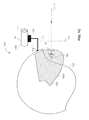
- FIG. 6 is a schematic illustration side view of a HMD system, constructed and operative in accordance with another embodiment of the disclosed technique.
- the disclosed technique overcomes the disadvantages of the prior art by providing a Helmet Mounted Display (HMD) system with a tinted visor and an image display goggle, located in front of the user's eye.
- the tinted visor includes a patch in front of the user's eye or eyes, the patch having greater light transmission than the tinted visor (although in certain cases, the patch may allow light transmission which is similar to the rest of the tinted visor). This allows the generated image to pass from the image display goggle directly toward the user's eye, without being attenuated by the tinted visor.
- the patch of the visor may be transparent and have constant un-tinted light transmission, or the patch may have controllable (i.e., adjustable) light transmission, which may be adjusted manually or automatically. It is noted that the patch may alternatively be a hole in the visor, from which the visor material is removed, allowing light to pass directly there through.
- the image display goggle includes an optical combiner, which directs a display image toward the user's eye.
- the combiner also allows for an image of the outside scene to pass there through, toward the user's eye.
- an optical cover which may be with controllable light transmission, is placed in front of the display goggle, in order to attenuate the brightness of the ambient scene, in a similar attenuation (i.e., light transmission) that the tinted visor attenuates the ambient light reaching the user's eyes.
- the image display goggle transmits the display generated image and the outside scene with similar brightness to the outside scene observed by the user through parts of the tinted visor, other than through the patch.
- the term “similar” as used herein with regard to the relation between the tint level of the optical cover and the tint level of the tinted visor refers to an acceptable ratio of light transmission between viewing the scene through the display goggle and viewing the scene directly through the tinted visor.
- Each user may tolerate (i.e., accept) a different level of this light-transmission ratio.
- the term “similar” in this regard refers to a range of tint levels, which may be applied to the optical cover, such that the light transmission ratio would be acceptable by the user.
- each user may further have the possibility of setting a different tint level to the optical cover, according to their respective individual tolerable light transmission ratio.
- FIG. 1A is a schematic illustration side view of a HMD system, generally referenced 100 , constructed and operative in accordance with an embodiment of the disclosed technique, in which the visor and the display goggle are in operative positions.
- FIG. 1B is a schematic illustration of the system of FIG. 1A , in which the display goggle is in an operative position and the visor is in a stowed position.
- FIG. 1C is a schematic illustration of the system of FIG. 1A , in which the visor is in an operative position and the display goggle is in a stowed position.
- FIG. 2 is a schematic illustration front view of the visor of FIG. 1A .
- FIG. 3 is a schematic illustration front view of the visor of FIG. 1C .
- HMD system 100 includes a tinted visor 102 , a display goggle 104 and an optical cover 112 .
- Tinted visor 102 is coupled with a helmet 108 .
- Display goggle 104 is coupled with helmet 108 , through an arm 110 , at a coupling interface 114 .
- Tinted visor 102 further includes a patch 116 , which has controllable light transmission.
- Display goggle 104 includes a first end 120 and a second end 122 .
- Display goggle 104 further includes an image generator 132 and an optical combiner 134 .
- Optical cover 112 has controllable light transmission, and is located in front of second end 122 of display goggle 104 .
- Image generator 132 generates an image, indicated by an arrow 136 , toward combiner 134 .
- Combiner 134 directs the generated image toward first end 120 .
- the transmission of patch 116 and of optical cover 112 may be adjusted, for example, electronically, optically, thermally, chemically and the like (i.e., adjustable patch transmission).
- patch 116 or optical cover 112 may be formed of materials with electrically controlled transmission, chemically adjustable transmission, thermally adjustable transmission, and the like.
- the light transmission of patch 116 or optical cover 112 may be controlled mechanically, by physically changing the elements with other elements having varying light transmission.
- the transmission of patch 116 or optical cover 112 may be adjusted passively, by employing photochromic materials, which darken when exposed to light of certain wavelength (such as ultraviolet light).
- optical cover 112 may be a filter, which filters out certain wavelengths.
- the user can remove optical cover 112 and replace it with other types of optical filters, according to the present ambient light.
- the transmission of patch 116 and of cover 112 may be controlled automatically, according to the degree of ambient light brightness.
- the degree of ambient light brightness may be obtained, for example, by a light detector (not shown), which may be located in the vicinity of visor 102 .
- patch transmission is controlled by light emitted from the display unit (e.g., light emitted from image generator 132 ).
- patch 116 is formed by photo-chromic materials, and thereby the light transmission of patch 116 can be controlled by the light emitted from image generator 132 .
- the disclosed technique enables aligning the position of patch 116 , and adjusting the size of patch 116 , to the projected image.
- the light transmission of patch 116 can be adjusted such that the more transparent area (i.e., the area of patch 116 that exhibits the largest light transmission) is optically aligned with the display unit. That is, the light transmission of the area of patch 116 which is optically aligned with the image provided by image generator 132 is adjusted to be of higher light transmission (i.e., more transparent) than the rest of patch 116 and of visor 102 . Additionally, the size of the transparent area of patch 116 is adjusted to correspond to the size of the projected image provided by image generator 132 . Thereby, the size of patch 116 is fitted to the dimensions of the projected image.
- Tinted visor 102 is moveable in a direction indicated by an arrow 118 , between an operative position 102 A and a stowed position 102 B ( FIG. 1B ).
- Patch 116 is located substantially in front of a user's eye 106 , when the visor is in operative position 102 A.
- Display goggle 104 is moveable between an operative position 104 A and a stowed position 104 C ( FIG. 1C ). In operative position 104 A, display goggle 104 is located in front of eye 106 , such that the optical axis (not shown) of the optical module substantially coincides with an optical axis 126 of eye 106 .
- the image generated by the image generator (e.g., symbology), indicated by an arrow 136 , reflects off of combiner 134 and passes along optical axis 126 toward eye 106 . Furthermore, light rays of a scene image, indicated by an arrow 124 , pass along optical axis 126 , through optical cover 112 and through combiner 134 toward eye 106 .
- the light transmission of optical cover 112 is set to be similar to the light transmission of tinted visor 102 .
- image generator 132 may be a standard power image generator, and does not have to be a high-power image generator, even when the ambient light conditions are very bright. The user thus is likely not to notice a difference in brightness between the generated images and the outside scene image.
- tinted visor 102 is shown from a front view indicated by dashed double-arrow line 138 in FIG. 1A . This view shows that patch 116 is located in front of eye 106 .
- tinted visor 102 is shaded, while patch 116 is clear, allowing more light to pass there through toward eye 106 , as described herein above.
- tinted visor 102 is located in stowed position 102 B, in which it is stowed away from the user's face (not shown) and eye 106 .
- a clear (i.e., un-tinted) visor (not shown) may be placed in front of the user's face, for example, a clear protective visor.
- Ambient light (not shown) may reach eye 106 directly (or through the clear visor), and not through tinted visor 102 .
- the user may move visor 102 to stowed position 102 B in various situations, for example, when the ambient light conditions are not bright, and there is no need for a tinted visor.
- Display goggle 104 is in operative position 104 A, located in front of eye 106 .
- Image 136 e.g., symbology
- Image 136 reflects off of combiner 134 and passes along optical axis 126 toward eye 106 .
- light rays of a scene image indicated by an arrow 124 , pass along optical axis 126 , through optical cover 112 and through combiner 134 toward eye 106 .
- optical cover 112 is set to be clear, allowing passage of light there through, without attenuating passing light.
- tinted visor 102 is located in operative position 102 A, in which it is located in front of the user's face, and patch 116 is located substantially in front of eye 106 .
- Display goggle 104 is located at a stowed position 104 C, such that it is moved away from the user's face. As depicted in FIG. 1C , display goggle 104 is located above the user's face, and substantially outside of the field of view of the user. The user may move display goggle 104 to stowed position 104 C in various situations when display is not desired or not required.
- patch 116 may have other optical characteristics, which differ from the rest of visor 102 (for example, chromaticity and the like). When each eye of the user views the outside scene through surfaces of different optical characteristics, it may cause certain discomfort to the viewing user.
- the visor may optionally include an additional patch (not shown), which is located in front of the other eye (not shown) of the user.
- additional patch may have adjustable optical characteristics.
- the light transmission of the first patch (as patch 116 ) is set to be similar to the light transmission of the rest of the tinted visor.
- the optical characteristics of the additional patch may be adjusted to be similar to the optical characteristics of the first patch. In this manner, both eyes of the user view the outside scene through surfaces with similar optical characteristics, thus avoiding the discomfort of each eye viewing through different optical characteristics.
- tinted visor 102 is shown from a front view indicated by dashed double-arrow line 144 in FIG. 1C . This view clearly shows that patch 116 is located in front of eye 106 . In the embodiment depicted in FIGS. 1C and 3 , both tinted visor 102 and patch 116 are similarly shaded, as described herein above.
- display system 100 may further include an emergency mechanism (not shown), coupled with coupling interface 114 .
- an emergency mechanism In an emergency occurrence, in which display goggle 104 may present a hazard to the user, the emergency mechanism would move display goggle 104 to stowed position 104 C.
- the emergency mechanism may disconnect coupling interface 114 completely, thereby removing display goggle from helmet 108 , and alleviating the hazard from the user.
- Such an emergency mechanism may include, for example, an accelerometer, for measuring the acceleration of the user's head during flight. In times of sudden acceleration, such as during a crash or sudden drop of an aircraft, the accelerometer may indicate that a state of emergency has occurred, and detach interface 114 , in order to remove display goggle 104 and prevent injury to the user.
- the HMD includes two display goggles, one for each eye of the user, and thus the tinted visor of the HMD includes two patches, each located between a respective display goggle and a respective eye.
- FIG. 4 is a schematic illustration front view of a HMD tinted visor, generally referenced 140 , constructed and operative in accordance with the other embodiment of the disclosed technique.
- Tinted visor 140 is shaded, and is similar to tinted visor 102 of FIG. 1A .
- Tinted visor 140 includes two patches, a right patch 142 R and a left patch 142 L, both of which may have controllable transmission.
- the degree of transmission may be adjusted manually or automatically, electronically or mechanically, similarly to patch 116 described above.
- Right patch 142 R is located in front of right eye 146 R, while left patch 142 L is located in front of left eye 146 L.
- the user can then observe a display through each eye, through the respective display goggle (not shown) and respective patch or patches 142 R and 142 L.
- HMD system 160 includes a tinted visor 162 , and a display goggle 164 .
- Tinted visor 162 is coupled with a helmet 168 .
- Display goggle 164 is coupled with helmet 168 , through an arm 170 , at a coupling interface 174 .
- Tinted visor 162 further includes a patch 176 , which has controllable light transmission.
- Display goggle 164 further includes an image generator 192 , an optical combiner 194 , and combiner tint cover 172 .
- Combiner tint cover 172 has controllable light transmission, and is located adjacent to combiner 194 , facing an outside scene, indicated by arrow 184 . It is noted that combiner tint cover 172 may be a tinted layer of combiner 196 , instead of a separate element. For the sake of simplicity, the present description will relate to combiner tint cover 172 as a separate element.
- Image generator 192 generates an image, indicated by an arrow 198 , toward the face of combiner 194 , which is facing eye 166 .
- Combiner 194 directs the generated image along optical axis 186 toward eye 166 .
- patch 176 and of combiner tint cover 172 may be adjusted, for example, electronically, optically, thermally, chemically and the like.
- patch 176 or optical cover 172 may be formed of materials with electrically controlled transmission, chemically adjustable transmission, thermally adjustable transmission, and the like.
- the light transmission of patch 176 or optical cover 172 may be controlled mechanically, by physically changing the elements with other elements having varying light transmission.
- the transmission of patch 176 or optical cover 172 may be adjusted passively, by employing photochromic materials, which darken when exposed to light of certain wavelength (such as ultraviolet light).
- optical cover 172 may be a filter, which filters out certain wavelengths.
- the user can remove optical cover 172 and replace it with other types of optical filters, according to the present ambient light. It is also noted that the transmission of patch 176 and of cover 172 may be controlled automatically, according to the degree of ambient light brightness.
- the degree of ambient light brightness may be obtained, for example, by a light detector (not shown), which may be located in the vicinity of visor 162 .
- patch transmission is controlled by light emitted from the display unit (e.g., light emitted from image generator 192 ).
- patch 176 is formed by photo-chromic materials, and thereby the light transmission of patch 176 can be controlled by the light emitted from image generator 192 .
- the disclosed technique enables aligning the position of patch 176 , and adjusting the size of patch 176 , to the projected image.
- the light transmission of patch 176 can be adjusted such that the more transparent area is optically aligned with the display unit. That is, the light transmission of the area of patch 176 which is optically aligned with the image provided by image generator 192 is adjusted to be more transparent than the rest of patch 176 and of visor 162 . Additionally, the size of the transparent area of patch 176 is adjusted to correspond to the size of the projected image provided by image generator 192 . Thereby, the size of patch 176 is fitted to the dimensions of the projected image.
- the patch transmission can be adjusted to be similar to the rest of the tinted visor.
- the projected image adjusts the light transmission of the patch, such that the light intensity of the projected image is similar to that of the ambient light arriving through the tinted area of the visor.
- Tinted visor 162 is moveable in a direction indicated by an arrow 178 , between an operative position 102 A and a stowed position (not shown).
- Patch 176 is located substantially in front of a user's eye 166 , when the visor is in operative position 162 A.
- Display goggle 164 is moveable between an operative position 104 A and a stowed position (not shown). In operative position 164 A, display goggle 164 is located in front of eye 166 , such that the optical axis (not shown) of combiner 194 substantially coincides with an optical axis 186 of eye 166 .
- the image generated by image generator 192 (e.g., symbology), indicated by an arrow 196 , reflects off of combiner 194 and passes along optical axis 186 toward eye 166 . Furthermore, light rays of an outside scene image, indicated by an arrow 184 , pass along optical axis 186 , through combiner tint cover 172 and through combiner 194 toward eye 166 .
- the light transmission of combiner tint cover 172 is set to be similar to the light transmission of tinted visor 162 .
- image generator 192 may be a standard power image generator, and does not have to be a high-power image generator, even when the ambient light conditions are very bright. The user thus is likely not to notice a difference in brightness between the generated images and the outside scene image.
- HMD system 200 includes a tinted visor 202 , a display goggle 204 and an optical cover 212 .
- Tinted visor 202 is coupled with a helmet 208 .
- Display goggle 204 is coupled with helmet 208 , through an arm 210 , at a coupling interface 214 .
- Tinted visor 202 further includes a patch 216 , which has controllable light transmission.
- Display goggle 204 includes a first end 220 and a second end 222 .
- Display goggle 204 further includes an image generator 232 , an image acquiring device 234 (e.g., a camera 234 ), and a display screen 236 .
- Display screen 236 is located proximate to first end 220 of display goggle 204 , such that display screen is located in front of patch 216 .
- Optical cover 212 has controllable light transmission, and is located in front of second end 222 of display goggle 204 .
- Display screen 236 is coupled with image generator 232 and with camera 234 .
- Camera 234 acquires an image of an outside scene, indicated by arrow 224 , passing through optical cover 212 . In this manner, light rays of outside scene 224 are attenuated by cover 212 , before reaching camera 234 .
- Camera 234 then transmits the acquired outside scene image for display on display screen 236 .
- Image generator 232 generates an image (not shown), which may include any user-required data, such as symbology, flight data and the like. The generated image is superimposed with the outside scene image, on display screen 236 .
- the light transmission of patch 216 and of optical cover 212 may be adjusted, for example, electronically, optically, thermally, chemically and the like.
- patch 216 or optical cover 212 may be formed of materials with electrically controlled light transmission, chemically adjustable light transmission, thermally adjustable light transmission, and the like.
- the light transmission of patch 216 or optical cover 212 may be controlled mechanically, by physically changing these elements with other elements having varying light transmission.
- the light transmission of patch 216 or optical cover 212 may be adjusted passively, by employing photochromic materials, which darken when exposed to light of certain wavelength (such as ultraviolet light).
- optical cover 212 may be a filter, which filters out certain wavelengths.
- the user can remove optical cover 212 and replace it with other types of optical filters, according to the present ambient light. It is also noted that the transmission of patch 216 and of cover 212 may be controlled automatically, according to the degree of ambient light brightness.
- the degree of ambient light brightness may be obtained, for example, by a light detector (not shown), which may be located in the vicinity of visor 202 .
- patch transmission is controlled by light emitted from the display unit.
- the patch is formed by photo-chromic materials, and thereby the light transmission of the patch can be controlled by the light emitted from the image generator.
- the disclosed technique enables aligning the position of the patch, and adjusting the size of the patch, to the projected image.
- Tinted visor 202 is moveable in a direction indicated by an arrow 218 , between an operative position 202 A and a stowed position (not shown).
- Patch 216 is located substantially in front of a user's eye 206 , when the visor is in operative position 202 A.
- Display goggle 204 is moveable between an operative position 204 A and a stowed position (not shown), similarly to display goggle 104 of FIGS. 1A , 1 B and 1 C.
- display goggle 204 In operative position 204 A, display goggle 204 is located in front of eye 206 , such that the optical axis (not shown) thereof substantially coincides with an optical axis 226 of eye 206 . In this manner, the images displayed on screen 236 are transmitted along optical axis 226 toward eye 206 .
- the light transmission of optical cover 212 is set to be similar to the light transmission of tinted visor 202 .
- the outside-scene image acquired by camera 234 is of similar brightness as the brightness of light rays (not shown) which reach eye 206 through other parts of visor 202 .
- image generator 232 may be a standard power image generator, and does not have to be a high-power image generator, even when the ambient light conditions are very bright. The user thus is likely not to notice a difference in brightness or contrast between the generated image and the outside scene image, both of which are superimposed on screen 236 .
Landscapes
- Physics & Mathematics (AREA)
- General Physics & Mathematics (AREA)
- Optics & Photonics (AREA)
Applications Claiming Priority (3)
| Application Number | Priority Date | Filing Date | Title |
|---|---|---|---|
| IL213727 | 2011-06-22 | ||
| IL213727A IL213727A (en) | 2011-06-22 | 2011-06-22 | A display system installed on a helmet suitable for bright ambient lighting conditions |
| PCT/IL2012/000261 WO2012176201A1 (fr) | 2011-06-22 | 2012-06-21 | Système d'affichage monté sur un casque pouvant être ajusté pour des conditions de lumière ambiante lumineuses |
Related Parent Applications (1)
| Application Number | Title | Priority Date | Filing Date |
|---|---|---|---|
| PCT/IL2012/000261 Continuation-In-Part WO2012176201A1 (fr) | 2011-06-22 | 2012-06-21 | Système d'affichage monté sur un casque pouvant être ajusté pour des conditions de lumière ambiante lumineuses |
Publications (2)
| Publication Number | Publication Date |
|---|---|
| US20140111864A1 US20140111864A1 (en) | 2014-04-24 |
| US9229237B2 true US9229237B2 (en) | 2016-01-05 |
Family
ID=45768449
Family Applications (1)
| Application Number | Title | Priority Date | Filing Date |
|---|---|---|---|
| US14/139,160 Active 2033-03-02 US9229237B2 (en) | 2011-06-22 | 2013-12-23 | Helmet mounted display system adjustable for bright ambient light conditions |
Country Status (3)
| Country | Link |
|---|---|
| US (1) | US9229237B2 (fr) |
| IL (1) | IL213727A (fr) |
| WO (1) | WO2012176201A1 (fr) |
Cited By (3)
| Publication number | Priority date | Publication date | Assignee | Title |
|---|---|---|---|---|
| US20190011702A1 (en) * | 2017-07-06 | 2019-01-10 | RAVR Incorporation Ltd. | Helmet-Mounted Visualization Device Without Parallax and its Operation Method |
| US11215828B1 (en) * | 2018-08-03 | 2022-01-04 | Rockwell Collins, Inc. | In field visor characterization for visor projected displays |
| US12153216B1 (en) | 2020-07-09 | 2024-11-26 | Apple Inc. | Electronic devices with optical component protection |
Families Citing this family (54)
| Publication number | Priority date | Publication date | Assignee | Title |
|---|---|---|---|---|
| US9158116B1 (en) | 2014-04-25 | 2015-10-13 | Osterhout Group, Inc. | Temple and ear horn assembly for headworn computer |
| US9715112B2 (en) | 2014-01-21 | 2017-07-25 | Osterhout Group, Inc. | Suppression of stray light in head worn computing |
| US9298007B2 (en) | 2014-01-21 | 2016-03-29 | Osterhout Group, Inc. | Eye imaging in head worn computing |
| CA2870148C (fr) * | 2012-04-30 | 2018-07-31 | Societe Anonyme Des Ets Catu | Casque de protection mecanique, electrique et contre les agressions thermiques, pour electriciens |
| FR3004817B1 (fr) * | 2013-04-19 | 2015-05-15 | Thales Sa | Systeme de visualisation hybride affichant des informations en superposition sur l exterieur |
| FR3011091A1 (fr) * | 2013-09-26 | 2015-03-27 | Valeo Vision | Lunettes a affichage de donnees munies d'un ecran anti-eblouissement |
| US9841599B2 (en) | 2014-06-05 | 2017-12-12 | Osterhout Group, Inc. | Optical configurations for head-worn see-through displays |
| US10684687B2 (en) | 2014-12-03 | 2020-06-16 | Mentor Acquisition One, Llc | See-through computer display systems |
| US9494800B2 (en) | 2014-01-21 | 2016-11-15 | Osterhout Group, Inc. | See-through computer display systems |
| US20150206173A1 (en) | 2014-01-21 | 2015-07-23 | Osterhout Group, Inc. | Eye imaging in head worn computing |
| US9746676B2 (en) | 2014-01-21 | 2017-08-29 | Osterhout Group, Inc. | See-through computer display systems |
| US11487110B2 (en) | 2014-01-21 | 2022-11-01 | Mentor Acquisition One, Llc | Eye imaging in head worn computing |
| US9766463B2 (en) | 2014-01-21 | 2017-09-19 | Osterhout Group, Inc. | See-through computer display systems |
| US9753288B2 (en) | 2014-01-21 | 2017-09-05 | Osterhout Group, Inc. | See-through computer display systems |
| US11892644B2 (en) | 2014-01-21 | 2024-02-06 | Mentor Acquisition One, Llc | See-through computer display systems |
| US9401540B2 (en) | 2014-02-11 | 2016-07-26 | Osterhout Group, Inc. | Spatial location presentation in head worn computing |
| US9389423B2 (en) * | 2014-03-11 | 2016-07-12 | Google Inc. | Head wearable display with adjustable transparency |
| US20160187651A1 (en) | 2014-03-28 | 2016-06-30 | Osterhout Group, Inc. | Safety for a vehicle operator with an hmd |
| US9733478B2 (en) | 2014-04-03 | 2017-08-15 | Thomson Licensing | Ambient light management for virtual reality glasses |
| US20150309534A1 (en) | 2014-04-25 | 2015-10-29 | Osterhout Group, Inc. | Ear horn assembly for headworn computer |
| US9672210B2 (en) | 2014-04-25 | 2017-06-06 | Osterhout Group, Inc. | Language translation with head-worn computing |
| US9423842B2 (en) | 2014-09-18 | 2016-08-23 | Osterhout Group, Inc. | Thermal management for head-worn computer |
| US10853589B2 (en) | 2014-04-25 | 2020-12-01 | Mentor Acquisition One, Llc | Language translation with head-worn computing |
| US9651787B2 (en) | 2014-04-25 | 2017-05-16 | Osterhout Group, Inc. | Speaker assembly for headworn computer |
| JP5978247B2 (ja) * | 2014-05-21 | 2016-08-24 | 株式会社東芝 | 表示装置 |
| US9995933B2 (en) * | 2014-06-24 | 2018-06-12 | Microsoft Technology Licensing, Llc | Display devices with transmittance compensation mask |
| US9625724B2 (en) * | 2014-09-04 | 2017-04-18 | Daqri, Llc | Retractable display for head mounted device |
| IL235088A (en) | 2014-10-07 | 2017-06-29 | Elbit Systems Ltd | Helmet system with variable light transmission coefficient |
| EP3215917B1 (fr) | 2014-11-05 | 2023-10-11 | Valve Corporation | Systèmes et procédés de rétroaction sensorielle pour guider des utilisateurs dans des environnements de réalité virtuelle |
| US9684172B2 (en) | 2014-12-03 | 2017-06-20 | Osterhout Group, Inc. | Head worn computer display systems |
| US20160239985A1 (en) | 2015-02-17 | 2016-08-18 | Osterhout Group, Inc. | See-through computer display systems |
| TWI585460B (zh) * | 2015-10-07 | 2017-06-01 | 中強光電股份有限公司 | 頭戴式裝置 |
| WO2017100074A1 (fr) * | 2015-12-11 | 2017-06-15 | Osterhout Group, Inc. | Systèmes informatiques d'affichage portés sur la tête |
| EP3405828A1 (fr) * | 2016-01-22 | 2018-11-28 | Corning Incorporated | Appareil d'affichage personnel à champ large |
| US9880441B1 (en) | 2016-09-08 | 2018-01-30 | Osterhout Group, Inc. | Electrochromic systems for head-worn computer systems |
| US10684478B2 (en) | 2016-05-09 | 2020-06-16 | Mentor Acquisition One, Llc | User interface systems for head-worn computers |
| US10466491B2 (en) | 2016-06-01 | 2019-11-05 | Mentor Acquisition One, Llc | Modular systems for head-worn computers |
| US10824253B2 (en) | 2016-05-09 | 2020-11-03 | Mentor Acquisition One, Llc | User interface systems for head-worn computers |
| DE102016112826A1 (de) * | 2016-07-13 | 2018-01-18 | Jabil Optics Germany GmbH | Detektionseinrichtung, HUD und Verfahren zum Betrieb eines HUD |
| US10690936B2 (en) | 2016-08-29 | 2020-06-23 | Mentor Acquisition One, Llc | Adjustable nose bridge assembly for headworn computer |
| USD840395S1 (en) | 2016-10-17 | 2019-02-12 | Osterhout Group, Inc. | Head-worn computer |
| US10209520B2 (en) | 2016-12-30 | 2019-02-19 | Microsoft Technology Licensing, Llc | Near eye display multi-component dimming system |
| USD864959S1 (en) | 2017-01-04 | 2019-10-29 | Mentor Acquisition One, Llc | Computer glasses |
| WO2018222892A1 (fr) * | 2017-06-01 | 2018-12-06 | Pogotec Inc. | Système de réalité augmentée à fixation amovible pour lunettes |
| FR3068481B1 (fr) * | 2017-06-29 | 2019-07-26 | Airbus Operations (S.A.S.) | Systeme et procede d'affichage pour un aeronef |
| US10976551B2 (en) | 2017-08-30 | 2021-04-13 | Corning Incorporated | Wide field personal display device |
| CN109725417B (zh) * | 2017-10-27 | 2024-04-09 | 江苏洪旭德生科技有限公司 | 基于光波导的深度处理数字光信号的方法及近眼显示装置 |
| US11982809B2 (en) * | 2018-09-17 | 2024-05-14 | Apple Inc. | Electronic device with inner display and externally accessible input-output device |
| EP3929651B1 (fr) * | 2019-02-19 | 2024-08-07 | JVCKenwood Corporation | Visiocasque |
| US20220155597A1 (en) * | 2019-03-27 | 2022-05-19 | Digades Gmbh Digitales Und Analoges Schaltungsdesign | Device for head-up projection, and helmet for the arrangement of a head-up projection device |
| KR102770689B1 (ko) * | 2019-08-30 | 2025-02-24 | 엘지전자 주식회사 | 머리에 착용할 수 있는 전자 디바이스 |
| KR102631786B1 (ko) * | 2020-06-24 | 2024-01-31 | 주식회사 레티널 | 상태 변환 광학 소자를 이용한 경량 증강 현실용 광학 장치 |
| IL280838B2 (en) * | 2021-02-11 | 2023-07-01 | Elbit Systems Ltd | System and method for removing obscuring objects in a head-up display |
| US11762205B1 (en) * | 2022-09-20 | 2023-09-19 | Rockwell Collins, Inc. | Method for creating uniform contrast on a headworn display against high dynamic range scene |
Citations (15)
| Publication number | Priority date | Publication date | Assignee | Title |
|---|---|---|---|---|
| DE1772014A1 (de) | 1967-03-21 | 1970-06-25 | Bendix Corp | Optische Anzeigeeinrichtung |
| EP0066402A1 (fr) | 1981-05-29 | 1982-12-08 | Gec Avionics Limited | Lunette de vision nocturne |
| US4449787A (en) | 1980-07-22 | 1984-05-22 | International Telephone And Telegraph Corporation | Night vision imaging system adapted for helmet mounting |
| GB2155762A (en) | 1984-03-12 | 1985-10-02 | Gec Avionics | Helmets |
| GB2161121A (en) | 1984-07-04 | 1986-01-08 | Ferranti Plc | Apparatus for the removal of helmet-mounted equipment |
| US5640711A (en) | 1993-12-10 | 1997-06-24 | Sextant Avionique | Head-mounted visor with variable transmission |
| US5835277A (en) | 1995-01-10 | 1998-11-10 | Raytheon Company | Modular helmet-mounted display |
| US5841408A (en) | 1994-10-08 | 1998-11-24 | Pilkington P.E. Limited | Head-up displays |
| US6008946A (en) | 1997-11-07 | 1999-12-28 | Honeywell, Inc. | Ambient light display illumination for a head-mounted display |
| US6049367A (en) | 1995-05-23 | 2000-04-11 | Colorlink, Inc. | Polarization manipulating device modulator with retarder stack which preconditions light for modulation and isotropic states |
| JP2009092808A (ja) | 2007-10-05 | 2009-04-30 | Nikon Corp | ヘルメットマウントディスプレイ装置 |
| JP2009092807A (ja) | 2007-10-05 | 2009-04-30 | Nikon Corp | ヘルメットマウントディスプレイ装置 |
| US20100053030A1 (en) | 2008-09-04 | 2010-03-04 | Sprague Randall B | Method and apparatus to process display and non-display information |
| US7893890B2 (en) | 2007-03-05 | 2011-02-22 | The Boeing Company | Electrically dimmable combiner optics for head-up display |
| EP2312373A1 (fr) | 2009-10-06 | 2011-04-20 | Thales | Equipement de vision comportant une lame optique à coefficient de transmission lumineuse commandée |
-
2011
- 2011-06-22 IL IL213727A patent/IL213727A/en active IP Right Grant
-
2012
- 2012-06-21 WO PCT/IL2012/000261 patent/WO2012176201A1/fr not_active Ceased
-
2013
- 2013-12-23 US US14/139,160 patent/US9229237B2/en active Active
Patent Citations (15)
| Publication number | Priority date | Publication date | Assignee | Title |
|---|---|---|---|---|
| DE1772014A1 (de) | 1967-03-21 | 1970-06-25 | Bendix Corp | Optische Anzeigeeinrichtung |
| US4449787A (en) | 1980-07-22 | 1984-05-22 | International Telephone And Telegraph Corporation | Night vision imaging system adapted for helmet mounting |
| EP0066402A1 (fr) | 1981-05-29 | 1982-12-08 | Gec Avionics Limited | Lunette de vision nocturne |
| GB2155762A (en) | 1984-03-12 | 1985-10-02 | Gec Avionics | Helmets |
| GB2161121A (en) | 1984-07-04 | 1986-01-08 | Ferranti Plc | Apparatus for the removal of helmet-mounted equipment |
| US5640711A (en) | 1993-12-10 | 1997-06-24 | Sextant Avionique | Head-mounted visor with variable transmission |
| US5841408A (en) | 1994-10-08 | 1998-11-24 | Pilkington P.E. Limited | Head-up displays |
| US5835277A (en) | 1995-01-10 | 1998-11-10 | Raytheon Company | Modular helmet-mounted display |
| US6049367A (en) | 1995-05-23 | 2000-04-11 | Colorlink, Inc. | Polarization manipulating device modulator with retarder stack which preconditions light for modulation and isotropic states |
| US6008946A (en) | 1997-11-07 | 1999-12-28 | Honeywell, Inc. | Ambient light display illumination for a head-mounted display |
| US7893890B2 (en) | 2007-03-05 | 2011-02-22 | The Boeing Company | Electrically dimmable combiner optics for head-up display |
| JP2009092808A (ja) | 2007-10-05 | 2009-04-30 | Nikon Corp | ヘルメットマウントディスプレイ装置 |
| JP2009092807A (ja) | 2007-10-05 | 2009-04-30 | Nikon Corp | ヘルメットマウントディスプレイ装置 |
| US20100053030A1 (en) | 2008-09-04 | 2010-03-04 | Sprague Randall B | Method and apparatus to process display and non-display information |
| EP2312373A1 (fr) | 2009-10-06 | 2011-04-20 | Thales | Equipement de vision comportant une lame optique à coefficient de transmission lumineuse commandée |
Non-Patent Citations (1)
| Title |
|---|
| International Search Report for International Application No. PCT/IL2012/000261 mailed Nov. 22, 2012 (11 pages). |
Cited By (3)
| Publication number | Priority date | Publication date | Assignee | Title |
|---|---|---|---|---|
| US20190011702A1 (en) * | 2017-07-06 | 2019-01-10 | RAVR Incorporation Ltd. | Helmet-Mounted Visualization Device Without Parallax and its Operation Method |
| US11215828B1 (en) * | 2018-08-03 | 2022-01-04 | Rockwell Collins, Inc. | In field visor characterization for visor projected displays |
| US12153216B1 (en) | 2020-07-09 | 2024-11-26 | Apple Inc. | Electronic devices with optical component protection |
Also Published As
| Publication number | Publication date |
|---|---|
| US20140111864A1 (en) | 2014-04-24 |
| IL213727A (en) | 2015-01-29 |
| IL213727A0 (en) | 2012-01-31 |
| WO2012176201A1 (fr) | 2012-12-27 |
Similar Documents
| Publication | Publication Date | Title |
|---|---|---|
| US9229237B2 (en) | Helmet mounted display system adjustable for bright ambient light conditions | |
| EP2194418B1 (fr) | Affichage tête haute pour lunettes pour voir la nuit | |
| JP5279733B2 (ja) | ヘッドアップディスプレイ用の電気的に減光可能なコンバイナ | |
| EP3204817B1 (fr) | Système de casque à émission de lumière ajustable | |
| KR101830364B1 (ko) | 심도 조절 기능을 구비한 증강 현실 구현 장치 | |
| CA1318528C (fr) | Lunettes compactes pour voir dans l'obscurite | |
| US10042161B2 (en) | Eye projection system | |
| US8079713B2 (en) | Near eye display system | |
| US9599813B1 (en) | Waveguide combiner system and method with less susceptibility to glare | |
| US9128285B2 (en) | Head-mounted display including integrated projector | |
| CN105137598B (zh) | 透明显示屏及其制备方法、光学系统和应用 | |
| EP2442170B1 (fr) | Dispositif d'affichage destiné à être porté sur la tête | |
| US11054639B2 (en) | Eye projection system | |
| CN110398837A (zh) | 具有可调节不透明度系统的头戴式设备 | |
| EP2349151B1 (fr) | Systeme de protection des yeux contre le laser divise split laser eye protection system | |
| US20130108229A1 (en) | Heads-up display including ambient light control | |
| WO2012049617A1 (fr) | Procédés et appareils de support d'adaptation d'oeil | |
| WO2017163058A1 (fr) | Filtres de protection contre le laser | |
| JP2016541003A (ja) | グレア防止スクリーンを備えるデータ表示眼鏡 | |
| CN109725416B (zh) | 眼球追踪光学系统、头戴式设备及成像方法 | |
| US10520724B2 (en) | Multi-wavelength head up display systems and methods | |
| CN115398290A (zh) | 用于设备中局部调光的数字投影仪 | |
| US20160116736A1 (en) | Head-up display for night vision goggles | |
| WO2023009657A1 (fr) | Atténuation de lumière bleue et correction de couleur dans des systèmes de réalité augmentée (ar), de réalité virtuelle (vr) ou de réalité étendue (xr) | |
| RU118786U1 (ru) | Нашлемная система индикации |
Legal Events
| Date | Code | Title | Description |
|---|---|---|---|
| AS | Assignment |
Owner name: ELBIT SYSTEMS LTD., ISRAEL Free format text: ASSIGNMENT OF ASSIGNORS INTEREST;ASSIGNORS:MARGULIS, MIRON;YAELI, JOSEPH;ABRAHAM, SASSAON;SIGNING DATES FROM 20131230 TO 20140204;REEL/FRAME:032205/0925 |
|
| STCF | Information on status: patent grant |
Free format text: PATENTED CASE |
|
| FEPP | Fee payment procedure |
Free format text: PAYOR NUMBER ASSIGNED (ORIGINAL EVENT CODE: ASPN); ENTITY STATUS OF PATENT OWNER: LARGE ENTITY |
|
| MAFP | Maintenance fee payment |
Free format text: PAYMENT OF MAINTENANCE FEE, 4TH YEAR, LARGE ENTITY (ORIGINAL EVENT CODE: M1551); ENTITY STATUS OF PATENT OWNER: LARGE ENTITY Year of fee payment: 4 |
|
| MAFP | Maintenance fee payment |
Free format text: PAYMENT OF MAINTENANCE FEE, 8TH YEAR, LARGE ENTITY (ORIGINAL EVENT CODE: M1552); ENTITY STATUS OF PATENT OWNER: LARGE ENTITY Year of fee payment: 8 |