US927733A - Method of operating alternating-current mercury wattmeters. - Google Patents
Method of operating alternating-current mercury wattmeters. Download PDFInfo
- Publication number
- US927733A US927733A US30030706A US1906300307A US927733A US 927733 A US927733 A US 927733A US 30030706 A US30030706 A US 30030706A US 1906300307 A US1906300307 A US 1906300307A US 927733 A US927733 A US 927733A
- Authority
- US
- United States
- Prior art keywords
- current
- mercury
- load
- disk
- shunt
- Prior art date
- Legal status (The legal status is an assumption and is not a legal conclusion. Google has not performed a legal analysis and makes no representation as to the accuracy of the status listed.)
- Expired - Lifetime
Links
Images
Classifications
-
- G—PHYSICS
- G01—MEASURING; TESTING
- G01R—MEASURING ELECTRIC VARIABLES; MEASURING MAGNETIC VARIABLES
- G01R11/00—Electromechanical arrangements for measuring time integral of electric power or current, e.g. of consumption
- G01R11/30—Dynamo-electric motor meters
Definitions
- ROBERT J. LANIIIIIQI, 0F h'lltlNttFIIlll
- ILLINOIS ASSIGNOR 'IO SANGAMO IQLIIU'IRIU COMPANY, Ob SIIAINttlIIQLl
- ILLINOIS A ("URIURAIION OF ILLINOIS.
- My invention relates to motor mercury watt-meters for m asuring alternating currents of electricity, and particularly to motor watt-meters of the mercury type in which the armature, preferably in the form of a disk, is immersed in mercury and is caused to rotate by the interaction of the load current or an aliquot portion thereof passing across the disk or across a portion thereot and a magnetic l'icld energized by a derived or shunt current; and its object is to provide a new and improved method oi? operating mercury motor wattunetersby an alternating current.
- the poles of a magnet enter the chamber in close proximity to the armature, and said magnet is energized to produce a magnetic field reacting with the load current by energizing coils which are in derived relation, or in shunt relation, to the main load current, or to the current passing through the disk and mercury chamber.
- energizing coils which are in derived relation, or in shunt relation, to the main load current, or to the current passing through the disk and mercury chamber.
- the armature consists of a copper disk immersed in a body of mercury and exposed to a strong magnetic lield, the arrangement being such that the main current traverses the disk diametrically, while IIIO'SIIUHI circuit passes through the energizing coils of the magnetic tield, whereby the disk is rotated.
- IIIO'SIIUHI circuit passes through the energizing coils of the magnetic tield, whereby the disk is rotated.
- my new and improved method consists in sending the main load current, or some definite aliquot portion thereof through the nua'cury chamber and disk, in energizing the magnetic held by an alternating current; oi the same 'lrequency as the main load current; in derived relation therewith, and in bringing the alternating current which onergizes the magnetic hold and the magnetic field into zero phasev relation with the impressed Il. Mill.
- alternating current which onergizes the magnetic hold and the magnetic field into zero phasev relation with the impressed Il. Mill.
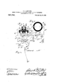
- -li igurc l is principally diugraininatic but in which parts are shown in vertical section;
- Fig. .2 is a View showing the mercury cup and disk iii-plan and the cooperating parts diametrically;
- Fig. 3 is a vector diagram.
- Reference letter A indicates a mercury cup formed of auy suitable insulating material.
- l3 designates a cover for the mercury cup, also n'iadc ofinsulating material, which is provided with a chamber Z).
- G designates a cap for closing the top of chamber i).
- g designates a vertical. spindle extending concentrically through the disk t ⁇ and to- Wliich the latter is atlixed.
- the lower end of the spindle is tapered and rests upon a conical bearing a. the latter being conveniently made in the form of ascrew which is inse ted in an opening through the bottom of the mercury cup.
- the portion of the spindle which extends upwardly through the chamber Z) has fixed thereon a counterweight'tl" while the upper end of the spindle is tapered and a conical bearing d,
- the latter being preferably formed as a screw supported by a yoke mounted upon the cap it thinible l depends from the cap G and concentrically surrounds the spindle g thereby preventing the escape from the chamber Z) of any mercury which may flow thercinto from the mercury cup when the latter occup es any other position than a vertical one.
- l and l? indicate the poles of a magnet which ciitc ugh the bottom wall of theincic' return path for the which is preferably "formed tal and is supported within 'etrical across the disk Ci;
- L ates one line of the power cuit is onnected tothe terminal Z while L l cates a continuation of the line etttcnding neetihg i ith any suitable translating apparatus such as indicated at ll. L indicates the return line extending from the translating apparatus L.
- the lines L" and L are connected in any suitable manner either from a dynamo or from a transformer such as ndicated at T.
- a shunt circuit n which includes an 'inductive resistance cxtendsfrom the line L to line If.
- the inductive resistance indicated in Fig. 1 consists in a core N, the winding of which is in the shunt circuit a, and a core a the energizing coil around which is connected in the main line L.
- the core N may preferably be formed of laminated metal and the poles thereof are spaced apart from the core n so as to form small air gaps 0' and 0
- Fig. 2 the inductive resistance of the current to pass through the disk.
- F designates a worm on the spindle g by means of which the rotary motion of the istering mechanism.
- rly adjusting the self-induction and capacity netisni in the shunt field may be obtained iand such ad ustment; may be conveniently (2 indicates a shunt circuit leading from the line L to the line U and comprising the: energizing coils c and e? which surroundin the shunt circuit n is shown as consistg G until the inductive resistance in the shunt increases sutliciently to cause practically all, 7
- disk G is communicated to any suitable reg- A portion of the current proportional to the line voltage. also passes through the shunt thereof is recorded upon suitable register- H impresses an electro-inotive the niagnetictield is eliminated.
- the condenser not onl impresses upon the shunt coils an E. F. in advance of the line pressure, but also increases the potential across the coils of the magnetic field so thatthe strength of the field is much greater than that obtained by connecting them directly across the orig inal line without the employmentof a condenser.- It has been found in practice that with a 100 volt 60.cyc1ecircuit; the condenser raises the pressure at least three or four times.
- the rotation of the disk G does not increase proportionally. as the load increases.
- This error is partially eliminated by the employment of the laminated metal return plate E for the magnetic lines owing to there being less eddy currents than'when the return plate is made of soft steel or cast iron.
- the remaining error is corrected by the inductive resistance located in shunt with the disk (1: which serves to the disk and consequently increasing its speed of rotation.
- the reactive resistance through the inductive shunt should increase as the load increases in proportion to the normal tendency of the speed of the disk to relatively fall behind the increase in load.
- the inductive resistance is preferably such as indicated in Fig. 1 in which all of the load current passes through the primary energi'zing turns around the core at so that on light load the primary coil has very little effect on the inductive shunt through the lead 'n, but on full load the primary coil has a very great ettect on the inductive resistance in the shunt by introducing into the coil of the resistance a counter E. M. F. sufficicut to cause practically infinite resistance through 'the shunt so that nearly all of the current passes through the disk thereby resultingiii maximum rotative lZOH no at full load, whereas on light load the cllect ot the primary winding is so slight upon the iiiductive shunt that. only about one-lialf of the total current at that load passes through the disk (l.
- the non-inductive resistance r serves to insure the passing of a portion of the current across the shunt n on light load.
- I may use an inductive resistance such as in- -dicated in Fig. 2, consisting in a choke coil in the shuntn and the yoke n which owing to the presence of the non inductive resistance r carries approximately half of the current around the disk on light load, but as the load increases the reactance increases,
Landscapes
- Physics & Mathematics (AREA)
- General Physics & Mathematics (AREA)
- Dynamo-Electric Clutches, Dynamo-Electric Brakes (AREA)
Description
. R. G. LANPHIER. METHOD OF OPERATING ALTERNATING CURRENT MERCURY WATTMETEBS.
APPLICATION FILED PEB.9, 1906.
Patented July 13, 1909.
M711 6,6, 6 5. wzwm UNITED STATES e TnNr GFFICE.
ROBERT (J. LANIIIIIQI, 0F h'lltlNttFIIlll), ILLINOIS, ASSIGNOR 'IO SANGAMO IQLIIU'IRIU COMPANY, Ob SIIAINttlIIQLl), ILLINOIS, A ("URIURAIION OF ILLINOIS.
METHOD QF'OPERATING ALTERNATING-OURRENT MERCURY \VA'I'TMETERS.
Specification of Letters Patent.
' Patented July 13, 1909.
Application fileil February 9, 1906. Serial No. 300,307.
1 '0 all whom it may concern:
Be it known that; l, ROBERT C. lnxxrnn-zn, a citizen of the United States, residing at Springfield, county of Sangamon, State of Illinois, have invented certain new and useful Improvements in the Method of Operating Alternating-Current Mercury \Vattmeters, 01 which the ftillowing is a full and complete specification, reference ing had to the accompanying drawings.
My invention relates to motor mercury watt-meters for m asuring alternating currents of electricity, and particularly to motor watt-meters of the mercury type in which the armature, preferably in the form of a disk, is immersed in mercury and is caused to rotate by the interaction of the load current or an aliquot portion thereof passing across the disk or across a portion thereot and a magnetic l'icld energized by a derived or shunt current; and its object is to provide a new and improved method oi? operating mercury motor wattunetersby an alternating current.
Ileretofore, it has been common to operate mercury motor meters by a direct current of electricity. Generally speaking, such me ters contain a chamber formed of or surrounded by non-magnetic material, and adapted to contain mercury. In this mercury. an arn'iature, connected. o'l'course, with usual registering mechanism, is completely submergedl The loadrurrcnt to be measured. or a deiinite aliquot part thereol'. enters the mercury chamber by suitable contact, and, massing through the mercury and across the armature, or across a portion of the armature, passes out of the mercury chamber by another contact and thence to the circuit and the translating devices. The poles of a magnet, suitably placed, enter the chamber in close proximity to the armature, and said magnet is energized to produce a magnetic field reacting with the load current by energizing coils which are in derived relation, or in shunt relation, to the main load current, or to the current passing through the disk and mercury chamber. Such a meter for direct currents is shown, for example, in Letters Patent of the United States to Mr. Gutmann and myself, No. 738,902, granted Sept. 15, I903. In this meter, the armature consists of a copper disk immersed in a body of mercury and exposed to a strong magnetic lield, the arrangement being such that the main current traverses the disk diametrically, while IIIO'SIIUHI circuit passes through the energizing coils of the magnetic tield, whereby the disk is rotated. The principles upon which that meter operates are well known, and need not be described here.
Ileretofore, I believe, no int'cgratingwattmeter of this type has been devised to measare an alternating current. If an alternating current be passed through the main load and energizing windings of such a meter, the grmit sell-induction produced by the alternating currents in the shunt energizing coil causes the phases of the currents in said energizing coiland therefore the phases in the said magnetic tieldto lag behind the phases of the current in the main load circuit so much that the field produced by said coils will have a dill'ercnce of phase from the impressed l'l. M.- I of some seventy degrees or moref ,\s a result of this difference in phase, the meter has almost no torque upon a non-imiut-tivc load, and with an inductive load it has a torque which will gradually increase as the power factor of the load decreases and the load current thereby comes more nearly in phase with the lagging IIHHQIILIIU licld.
It: is the object of my invention to provide a new and improved method by which a \.'att-meter ol this type may be operated by an alternating current, and, broadly speaking, my new and improved method consists in sending the main load current, or some definite aliquot portion thereof through the nua'cury chamber and disk, in energizing the magnetic held by an alternating current; oi the same 'lrequency as the main load current; in derived relation therewith, and in bringing the alternating current which onergizes the magnetic hold and the magnetic field into zero phasev relation with the impressed Il. Mill. By this means thepolarity of the magnetic field alternates with the.
same frequency as the alternations of the main load current and at the same tinic therewith, causing the armature to rotate.
l have shown in the drawings one form of apparatus by which my new and improved method may carried out.
In the drawings -li igurc l is principally diugraininatic but in which parts are shown in vertical section; Fig. .2 is a View showing the mercury cup and disk iii-plan and the cooperating parts diametrically; and Fig. 3 is a vector diagram.
Similarreterence characters are used to designate similar parts in the several figures oi" the drawing.
Reference letter A indicates a mercury cup formed of auy suitable insulating material.
l3 designates a cover for the mercury cup, also n'iadc ofinsulating material, which is provided with a chamber Z).
G designates a cap for closing the top of chamber i).
A. disk of good conducting material, such as copper, is immersed in the mercury M in the cup A. v
g designates a vertical. spindle extending concentrically through the disk t} and to- Wliich the latter is atlixed. The lower end of the spindle is tapered and rests upon a conical bearing a. the latter being conveniently made in the form of ascrew which is inse ted in an opening through the bottom of the mercury cup. The portion of the spindle which extends upwardly through the chamber Z) has fixed thereon a counterweight'tl" while the upper end of the spindle is tapered and a conical bearing d,
the latter being preferably formed as a screw supported by a yoke mounted upon the cap it thinible l depends from the cap G and concentrically surrounds the spindle g thereby preventing the escape from the chamber Z) of any mercury which may flow thercinto from the mercury cup when the latter occup es any other position than a vertical one.
l and l? indicate the poles of a magnet which ciitc ugh the bottom wall of theincic' return path for the which is preferably "formed tal and is supported within 'etrical across the disk Ci;
indicate e nductor terminals of laiui at c" is d through mercury cup in. the some ho izons-a1 plane as the disk G and at diametrically opposite points.
L ates one line of the power cuit is onnected tothe terminal Z while L l cates a continuation of the line etttcnding neetihg i ith any suitable translating apparatus such as indicated at ll. L indicates the return line extending from the translating apparatus L. The lines L" and L are connected in any suitable manner either from a dynamo or from a transformer such as ndicated at T.
the cores E and E of the magnet. Located in series with the coils a and c and inter; posed between the same and the line L is condenserli.
A shunt circuit n which includes an 'inductive resistance cxtendsfrom the line L to line If. The inductive resistance indicated in Fig. 1 consists in a core N, the winding of which is in the shunt circuit a, and a core a the energizing coil around which is connected in the main line L. The core N may preferably be formed of laminated metal and the poles thereof are spaced apart from the core n so as to form small air gaps 0' and 0 In Fig. 2 the inductive resistance of the current to pass through the disk.
F designates a worm on the spindle g by means of which the rotary motion of the istering mechanism.
The operation of my invention 13 as follows: The alternating current passes from line Lnon-inductive resistance 7', terminal lating apparatus L, thence through the return line if to the'dynaino or: transformer.
circuit 6, windings c and c of the magnetic field, condenser H to the return line if. The reaction of the magnetic field upon the disk 1 rotates the latter and the rotation apparatus operatively .co nnccted to the worm F in. any usual or well-known manner. The con force on the coils e" and c thereby bringing the magnetic field produced by them inphase with thclinc pressure on non-inductive load. The lagging of the current in the coils e and 6 due to their sell-induction is thereby overcome-so that tllfditl'er ence in phase between the impressed ill. MfF. and
rly adjusting the self-induction and capacity netisni in the shunt field may be obtained iand such ad ustment; may be conveniently (2 indicates a shunt circuit leading from the line L to the line U and comprising the: energizing coils c and e? which surroundin the shunt circuit n is shown as consistg G until the inductive resistance in the shunt increases sutliciently to cause practically all, 7
disk G is communicated to any suitable reg- A portion of the current proportional to the line voltage. also passes through the shunt thereof is recorded upon suitable register- H impresses an electro-inotive the niagnetictield is eliminated. Bypropoil the system any desired phase of the magthe dynamo or transformer T through the Z, disk G, terminal Z", line L to the transhis accomplished by using fixed coils and a variable condenser, 30- that the meter may be readily adjusted to measure correctlv eitherl a non-inductive or an inductive load to the ally illustrated in the vector diagram in Figf 3, in which E indicates the impressed line lowest possible factor.
The condenser not onl impresses upon the shunt coils an E. F. in advance of the line pressure, but also increases the potential across the coils of the magnetic field so thatthe strength of the field is much greater than that obtained by connecting them directly across the orig inal line without the employmentof a condenser.- It has been found in practice that with a 100 volt 60.cyc1ecircuit; the condenser raises the pressure at least three or four times.
The operation above described is graphicpressure; 0 the main current on non-in ductive load; C the main current. on inductive load; S the shunt current through the coils e and 6 lagging 80- degrees when the shunt is connected aci oss the circuit; M the magnetic field of the shunt, the phase of which is that of the shunt current S; E the pressure impressed on the shunt coils e and 6 when the condenser is used, the phase being 80 degrees in advance of and greater than that of the line pressure E; S the-current in the shunt coils due to E, the pressure impressed by the condenser; and M? the magnetism which is in phase witht-he line pressure E owing to the pressure impressed on the coils by the condenser."
As previously stated, the rotation of the disk G does not increase proportionally. as the load increases. This error is partially eliminated by the employment of the laminated metal return plate E for the magnetic lines owing to there being less eddy currents than'when the return plate is made of soft steel or cast iron. The remaining error is corrected by the inductive resistance located in shunt with the disk (1: which serves to the disk and consequently increasing its speed of rotation. The reactive resistance through the inductive shunt should increase as the load increases in proportion to the normal tendency of the speed of the disk to relatively fall behind the increase in load.
The inductive resistance is preferably such as indicated in Fig. 1 in which all of the load current passes through the primary energi'zing turns around the core at so that on light load the primary coil has very little effect on the inductive shunt through the lead 'n, but on full load the primary coil has a very great ettect on the inductive resistance in the shunt by introducing into the coil of the resistance a counter E. M. F. sufficicut to cause practically infinite resistance through 'the shunt so that nearly all of the current passes through the disk thereby resultingiii maximum rotative lZOH no at full load, whereas on light load the cllect ot the primary winding is so slight upon the iiiductive shunt that. only about one-lialf of the total current at that load passes through the disk (l.
It is obviously a simple matter to so adjust the relativc. primary and secondary coils in the shunting device just described as to compensate for the normal tendency of the disk to relatively fall behind in its speed of rotation as the load increases. The non-inductive resistance r serves to insure the passing of a portion of the current across the shunt n on light load.
The presence of the air gaps 0 and 0 in .the magnetic circuit of. the shunting device is of importance inasmuch as in a closed magnetic circuit the effect of the shunting -device will not; increase properly with the increasing load, as on very light load the magnetism will be lower -in proportion for the magnetizing force than on heavier loads.
This is due to the fact that the magnetism of soft iron initially increases very slowly with the magnetizing force and consequently by introducing an air gap in the magnetic circuit of the shunting device enou h primary turns can be employed to initial? magnetize the coil sutliciently for the lightest loads which the meter must measure, and the ma etization will then increase up to the big est load which the 'meter is adapted to measure.
In lieu of the inductive resistance above described, which is preferably employed, I may use an inductive resistance such as in- -dicated in Fig. 2, consisting in a choke coil in the shuntn and the yoke n which owing to the presence of the non inductive resistance r carries approximately half of the current around the disk on light load, but as the load increases the reactance increases,
thereby sending through the disk a greater proportion of the main current as the load increases.
What I claim as new and desire to secure by Letters Patent is -1. The method of operating a mercury motor watt-meter on alternating current which consists in bringin the current in the pressure circuit into p ase with the impressed electro-motive force.
2-. The method of operating mercury motor watt-meters on alternating current which consists in bringing the magnetic effect of the current of the pressure circuit into zero phase relation with the impressed electroniotive force. 4
3. The method of operating by an alternat'mg current-a mercury Watt motor meter {said energizing unenbintozero phase rela which congi'sts in diriecting tlie alternating ytion with the impressed electro-m'otive force cur'rentto emeasure ,or ana not ortion 3 41 ,-there0f, through the-motor ele xent 'of the ROBERT LANPHI -5- meter, and in energizing the-magnetic field Witnesses:
by an alternating current of the same fre J. H. Honnm,
que ncy :rs, the load. current, and by bringing A.- D. BRINKERHOFF.
Priority Applications (1)
| Application Number | Priority Date | Filing Date | Title |
|---|---|---|---|
| US30030706A US927733A (en) | 1906-02-09 | 1906-02-09 | Method of operating alternating-current mercury wattmeters. |
Applications Claiming Priority (1)
| Application Number | Priority Date | Filing Date | Title |
|---|---|---|---|
| US30030706A US927733A (en) | 1906-02-09 | 1906-02-09 | Method of operating alternating-current mercury wattmeters. |
Publications (1)
| Publication Number | Publication Date |
|---|---|
| US927733A true US927733A (en) | 1909-07-13 |
Family
ID=2996159
Family Applications (1)
| Application Number | Title | Priority Date | Filing Date |
|---|---|---|---|
| US30030706A Expired - Lifetime US927733A (en) | 1906-02-09 | 1906-02-09 | Method of operating alternating-current mercury wattmeters. |
Country Status (1)
| Country | Link |
|---|---|
| US (1) | US927733A (en) |
-
1906
- 1906-02-09 US US30030706A patent/US927733A/en not_active Expired - Lifetime
Similar Documents
| Publication | Publication Date | Title |
|---|---|---|
| US927733A (en) | Method of operating alternating-current mercury wattmeters. | |
| US2204916A (en) | Electric motor | |
| US1674477A (en) | Electric apparatus | |
| US1772091A (en) | Integrating method and apparatus | |
| US675996A (en) | Electric meter. | |
| US745461A (en) | Alternating-current meter. | |
| US407619A (en) | Electric meter | |
| US870970A (en) | Alternating-current meter. | |
| US833205A (en) | Electric meter. | |
| US698675A (en) | Electric meter. | |
| US643162A (en) | Alternating-current meter. | |
| US573079A (en) | Meter for measuring electric currents | |
| US1655604A (en) | Electricity meter | |
| US1745868A (en) | Electrical measuring instrument | |
| US843155A (en) | Motor-meter for alternating currents and method of operating the same. | |
| US1308656A (en) | Excess-demand meter | |
| US1157926A (en) | Electric meter. | |
| US698659A (en) | Motor-meter. | |
| US583951A (en) | Motor-meter | |
| US698665A (en) | Alternating-current meter. | |
| US698649A (en) | Electric meter. | |
| US551436A (en) | Electric meter | |
| US667028A (en) | Electric meter. | |
| US623530A (en) | Electric meter | |
| US623529A (en) | Electric meter |