US9297357B2 - Blade insert for a wind turbine rotor blade - Google Patents
Blade insert for a wind turbine rotor blade Download PDFInfo
- Publication number
- US9297357B2 US9297357B2 US13/856,635 US201313856635A US9297357B2 US 9297357 B2 US9297357 B2 US 9297357B2 US 201313856635 A US201313856635 A US 201313856635A US 9297357 B2 US9297357 B2 US 9297357B2
- Authority
- US
- United States
- Prior art keywords
- blade
- scarfed
- insert
- edge
- segment
- Prior art date
- Legal status (The legal status is an assumption and is not a legal conclusion. Google has not performed a legal analysis and makes no representation as to the accuracy of the status listed.)
- Active, expires
Links
Images




Classifications
-
- F—MECHANICAL ENGINEERING; LIGHTING; HEATING; WEAPONS; BLASTING
- F03—MACHINES OR ENGINES FOR LIQUIDS; WIND, SPRING, OR WEIGHT MOTORS; PRODUCING MECHANICAL POWER OR A REACTIVE PROPULSIVE THRUST, NOT OTHERWISE PROVIDED FOR
- F03D—WIND MOTORS
- F03D1/00—Wind motors with rotation axis substantially parallel to the air flow entering the rotor
- F03D1/06—Rotors
- F03D1/0608—Rotors characterised by their aerodynamic shape
- F03D1/0633—Rotors characterised by their aerodynamic shape of the blades
- F03D1/0641—Rotors characterised by their aerodynamic shape of the blades of the section profile of the blades, i.e. aerofoil profile
-
- F03D1/001—
-
- F—MECHANICAL ENGINEERING; LIGHTING; HEATING; WEAPONS; BLASTING
- F03—MACHINES OR ENGINES FOR LIQUIDS; WIND, SPRING, OR WEIGHT MOTORS; PRODUCING MECHANICAL POWER OR A REACTIVE PROPULSIVE THRUST, NOT OTHERWISE PROVIDED FOR
- F03D—WIND MOTORS
- F03D1/00—Wind motors with rotation axis substantially parallel to the air flow entering the rotor
- F03D1/06—Rotors
- F03D1/065—Rotors characterised by their construction elements
-
- F—MECHANICAL ENGINEERING; LIGHTING; HEATING; WEAPONS; BLASTING
- F03—MACHINES OR ENGINES FOR LIQUIDS; WIND, SPRING, OR WEIGHT MOTORS; PRODUCING MECHANICAL POWER OR A REACTIVE PROPULSIVE THRUST, NOT OTHERWISE PROVIDED FOR
- F03D—WIND MOTORS
- F03D1/00—Wind motors with rotation axis substantially parallel to the air flow entering the rotor
- F03D1/06—Rotors
- F03D1/065—Rotors characterised by their construction elements
- F03D1/0675—Rotors characterised by their construction elements of the blades
-
- F03D1/0683—
-
- F—MECHANICAL ENGINEERING; LIGHTING; HEATING; WEAPONS; BLASTING
- F03—MACHINES OR ENGINES FOR LIQUIDS; WIND, SPRING, OR WEIGHT MOTORS; PRODUCING MECHANICAL POWER OR A REACTIVE PROPULSIVE THRUST, NOT OTHERWISE PROVIDED FOR
- F03D—WIND MOTORS
- F03D13/00—Assembly, mounting or commissioning of wind motors; Arrangements specially adapted for transporting wind motor components
- F03D13/10—Assembly of wind motors; Arrangements for erecting wind motors
-
- F—MECHANICAL ENGINEERING; LIGHTING; HEATING; WEAPONS; BLASTING
- F05—INDEXING SCHEMES RELATING TO ENGINES OR PUMPS IN VARIOUS SUBCLASSES OF CLASSES F01-F04
- F05B—INDEXING SCHEME RELATING TO WIND, SPRING, WEIGHT, INERTIA OR LIKE MOTORS, TO MACHINES OR ENGINES FOR LIQUIDS COVERED BY SUBCLASSES F03B, F03D AND F03G
- F05B2240/00—Components
- F05B2240/20—Rotors
- F05B2240/30—Characteristics of rotor blades, i.e. of any element transforming dynamic fluid energy to or from rotational energy and being attached to a rotor
- F05B2240/302—Segmented or sectional blades
-
- Y—GENERAL TAGGING OF NEW TECHNOLOGICAL DEVELOPMENTS; GENERAL TAGGING OF CROSS-SECTIONAL TECHNOLOGIES SPANNING OVER SEVERAL SECTIONS OF THE IPC; TECHNICAL SUBJECTS COVERED BY FORMER USPC CROSS-REFERENCE ART COLLECTIONS [XRACs] AND DIGESTS
- Y02—TECHNOLOGIES OR APPLICATIONS FOR MITIGATION OR ADAPTATION AGAINST CLIMATE CHANGE
- Y02E—REDUCTION OF GREENHOUSE GAS [GHG] EMISSIONS, RELATED TO ENERGY GENERATION, TRANSMISSION OR DISTRIBUTION
- Y02E10/00—Energy generation through renewable energy sources
- Y02E10/70—Wind energy
- Y02E10/72—Wind turbines with rotation axis in wind direction
-
- Y02E10/721—
-
- Y—GENERAL TAGGING OF NEW TECHNOLOGICAL DEVELOPMENTS; GENERAL TAGGING OF CROSS-SECTIONAL TECHNOLOGIES SPANNING OVER SEVERAL SECTIONS OF THE IPC; TECHNICAL SUBJECTS COVERED BY FORMER USPC CROSS-REFERENCE ART COLLECTIONS [XRACs] AND DIGESTS
- Y10—TECHNICAL SUBJECTS COVERED BY FORMER USPC
- Y10T—TECHNICAL SUBJECTS COVERED BY FORMER US CLASSIFICATION
- Y10T29/00—Metal working
- Y10T29/49—Method of mechanical manufacture
- Y10T29/49316—Impeller making
- Y10T29/49336—Blade making
- Y10T29/49337—Composite blade
Definitions
- the present subject matter relates generally to wind turbines and, more particularly, to a blade insert for extending the length of a wind turbine rotor blade.
- Wind power is considered one of the cleanest, most environmentally friendly energy sources presently available, and wind turbines have gained increased attention in this regard.
- a modern wind turbine typically includes a tower, generator, gearbox, nacelle, and one or more turbine blades.
- the turbine blades capture kinetic energy from wind using known foil principles and transmit the kinetic energy through rotational energy to turn a shaft coupling the rotor blades to a gearbox, or if a gearbox is not used, directly to the generator.
- the generator then converts the mechanical energy to electrical energy that may be deployed to a utility grid.
- a conventional tip extension is installed onto a rotor blade by cutting-off a portion of the blade at its tip and replacing such cut-off portion with the tip extension.
- the tip extension must be significantly longer than the actual increase in rotor blade length that can be achieved by installing the extension.
- a conventional tip extension may often need to have a length of almost half of the original span of the rotor blade to accommodate the increased loading on the blade. As such, due to their length, the costs of manufacturing and transporting conventional tip extensions can be prohibitively expensive.
- a blade insert that can be used to increase the span of a rotor blade by an amount generally corresponding to the overall length of the blade insert would be welcomed in the technology.
- the present subject matter is directed to a rotor blade assembly for a wind turbine.
- the rotor blade assembly may generally include a first blade segment defining a first joint end, a second blade segment defining a second joint end and a blade insert extending between a forward end coupled to the first blade segment and an aft end coupled to the second blade segment.
- the blade insert may include a top side extending between a forward edge and an aft edge.
- the top side may define a top scarfed section at its forward edge.
- the blade insert may also include a bottom side extending between a forward edge and an aft edge.
- the bottom side may define a bottom scarfed section at its forward edge.
- At least a portion of the forward edge of the top side may be offset relative to the forward edge of the bottom side such that an access window is defined between the top side and the first blade segment when the forward end of the blade insert is positioned adjacent to the first joint end of the first blade segment.
- the present subject matter is directed to a blade segment for coupling a first blade segment to a second blade segment.
- the blade segment may generally include an aerodynamic body extending between a forward end configured to be coupled to the first blade segment and an aft end configured to be coupled to the second blade segment.
- the aerodynamic body may include a top side extending between a forward edge and an aft edge.
- the top side may define a top scarfed section at its forward edge.
- the aerodynamic body may further include a bottom side extending between a forward edge and an aft edge.
- the bottom side may define a bottom scarfed section at its forward edge. Additionally, at least a portion of the forward edge of the top side may be configured to be offset relative to the forward edge of the bottom side.
- the present subject matter is directed to a method for assembling a blade insert between a first blade segment and a second blade segment.
- the blade insert may include a top side extending between a forward edge and an aft edge and a bottom side extending between a forward edge and an aft edge.
- the method may generally include positioning a forward end of the blade insert adjacent to a first joint end of the first blade segment. At least a portion of the forward edge of the top side may be offset relative to the forward edge of the bottom side such that an access window is defined between the blade insert and the first blade segment.
- the method may include positioning a bottom scarfed connector between a bottom scarfed section defined in the bottom side of the blade insert and a bottom scarfed section defined in the first blade segment, positioning a window cover across at least a portion of the access window and positioning a top scarfed connector between a top scarfed section defined in the top side of the blade insert and a top scarfed section defined in the first blade segment.
- FIG. 1 illustrates a perspective view of one embodiment of a wind turbine
- FIG. 2 illustrates a perspective view of one embodiment of one of the rotor blades of the wind turbine shown in FIG. 1 ;
- FIG. 3 illustrates an exploded view of one embodiment of a rotor blade assembly in accordance with aspects of the present subject matter
- FIG. 4 illustrates a perspective view of one embodiment of a suitable blade insert configuration that may be utilized with the disclosed rotor blade assembly in accordance with aspects of the present subject matter
- FIG. 5 illustrates a cross-sectional view of the blade insert shown in FIG. 4 taken about line 5 - 5 ;
- FIG. 6 illustrates a perspective view of one embodiment of a suitable blade segment configuration that may be utilized with the disclosed rotor blade assembly in accordance with aspects of the present subject matter
- FIG. 7 illustrates an exploded view of a portion of one embodiment of the disclosed rotor blade assembly, particularly illustrating the rotor blade assembly including the blade insert shown in FIGS. 4 and 5 and the blade segment shown in FIG. 6 ;
- FIG. 8 illustrates a perspective, assembled view of the components shown in FIG. 7 ;
- FIG. 9 illustrates a cross-sectional view of a portion of the rotor blade assembly shown in FIG. 8 taken about line 9 - 9 ;
- FIG. 10 illustrates a perspective view of another embodiment of a suitable blade insert configuration that may be utilized with the disclosed rotor blade assembly in accordance with aspects of the present subject matter
- FIG. 11 illustrates a cross-sectional view of a portion of the blade insert shown in FIG. 10 taken about line 11 - 11 ;
- FIG. 12 illustrates a perspective view of another embodiment of a suitable blade segment configuration that may be utilized with the disclosed rotor blade assembly in accordance with aspects of the present subject matter
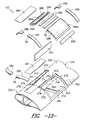
- FIG. 13 illustrates an exploded view of a portion of one embodiment of the disclosed rotor blade assembly, particularly illustrating the rotor blade assembly including the blade insert shown in FIGS. 10 and 11 and the blade segment shown in FIG. 12 ;
- FIG. 14 illustrates a perspective, assembled view of the components shown in FIGS. 13 ;
- FIG. 15 illustrates a cross-sectional view of a portion of the rotor blade assembly shown in FIG. 14 taken about line 15 - 15 .
- the present subject matter is directed to a blade insert configured to be secured between separate blade segments of a wind turbine rotor blade.
- the blade insert may be installed between the blade segments as a one-piece construction (as opposed to installing the blade segment in two or more pieces, such as by installing separate shell halves of an insert between the blade segments).
- the blade insert may be configured such that certain access features (e.g., access windows) are defined between the insert and the blade segments to permit the ends of the blade insert to be secured to the joint end of each blade segment.
- various assembly components e.g., scarfed connectors, shell inserts, window covers, etc. may be installed between the blade insert and the blade segment to facilitate coupling such components to one another.
- FIG. 1 illustrates a perspective view of one embodiment of a wind turbine 10 .
- the wind turbine 10 generally includes a tower 12 extending from a support surface 14 , a nacelle 16 mounted on the tower 12 , and a rotor 18 coupled to the nacelle 16 .
- the rotor 18 includes a rotatable hub 20 and at least one rotor blade 22 coupled to and extending outwardly from the hub 20 .
- the rotor 18 includes three rotor blades 22 .
- the rotor 18 may include more or less than three rotor blades 22 .
- Each rotor blade 22 may be spaced about the hub 20 to facilitate rotating the rotor 18 to enable kinetic energy to be transferred from the wind into usable mechanical energy, and subsequently, electrical energy.
- the hub 20 may be rotatably coupled to an electric generator (not shown) positioned within the nacelle 16 to permit electrical energy to be produced.
- the rotor blade 22 generally includes a blade root 24 configured for mounting the rotor blade 22 to the hub 20 of the wind turbine 10 ( FIG. 1 ) and a blade tip 26 disposed opposite the blade root 24 .
- a body 28 of the rotor blade 22 may generally be configured to extend between the blade root 24 and the blade tip 26 and may serve as the outer casing/skin of the blade 22 .
- the body 28 may define a substantially aerodynamic profile, such as by defining a symmetrical or cambered airfoil-shaped cross-section.
- the body 28 may include a pressure side 30 and a suction side 32 extending between a leading edge 34 and a trailing edge 36 .
- the rotor blade 22 may have a span 38 defining the total length between the blade root 22 and the blade tip 24 and a chord 40 defining the total length between the leading edge 34 and the trialing edge 36 .
- the chord 40 may vary in length with respect to the span 38 as the rotor blade 22 extends from the blade root 22 to the blade tip 24 .
- the body 28 of the rotor blade 22 may be formed as a single, unitary component.
- the body 28 may be formed from a plurality of shell components.
- the body 28 may be manufactured from a first shell half generally defining the pressure side 30 of the rotor blade 22 and a second shell half generally defining the suction side 32 of the rotor blade 20 , with the shell halves being secured to one another at the leading and trailing edges 34 , 36 of the blade 22 .
- the body 28 may generally be formed from any suitable material.
- the body 28 may be formed entirely from a laminate composite material, such as a carbon fiber reinforced laminate composite or a glass fiber reinforced laminate composite.
- one or more portions of the body 28 may be configured as a layered construction and may include a core material 42 (e.g., as shown in FIG. 6 ), formed from a lightweight material such as wood (e.g., balsa), foam (e.g., extruded polystyrene foam) or a combination of such materials, disposed between layers of laminate composite material.
- a core material 42 e.g., as shown in FIG. 6
- a lightweight material such as wood (e.g., balsa), foam (e.g., extruded polystyrene foam) or a combination of such materials, disposed between layers of laminate composite material.
- the rotor blade 22 may also include one or more longitudinally extending structural components configured to provide increased stiffness, buckling resistance and/or strength to the rotor blade 22 .
- the rotor blade 22 may include a pair of spar caps (e.g., a top spar cap 44 and a bottom spar cap 46 ) and one or more shear webs 48 extending between the opposed spar caps 44 , 46 (e.g., as shown in FIG. 6 ).
- the rotor blade assembly 100 may include a first blade segment 102 (or 202 ), a second blade segment 104 (or 204 ) and a blade insert 106 (or 206 ) configured to be coupled between the first and second blade segments 102 , 104 .
- the rotor blade assembly 100 may be configured such that, when the first and second blade segments 102 , 104 are coupled together via the blade insert 106 , a complete rotor blade is formed.
- the first and second blade segments 102 , 104 may be formed by dividing a pre-existing rotor blade 22 into two separate blade sections.
- the illustrated rotor blade 22 may be divided into the first and second blade segments 102 , 104 by cutting the rotor blade 22 along a joint or cut line 108 .
- the first blade segment 102 may correspond to a root segment of the rotor blade 22 and may extend between the blade root 24 and a first joint end 110 formed at the cut line 108 .
- the second blade segment 104 may correspond a tip segment of the rotor blade 22 and may extend between the blade tip 26 and a second joint end 112 formed at the cut line 108 .
- first blade segment 102 is shown as a root segment and the second blade segment 104 is shown as a tip segment
- first blade segment and second blade segment may generally refer to any suitable segments or sections of the rotor blade 22 .
- first blade segment 102 may correspond to a tip segment of the rotor blade 22 and the second blade segment 104 may correspond to a root segment of the rotor blade 22 .
- first and second blade segments 102 , 104 may correspond to shorter segments of the rotor blade 22 .
- first blade segment and second blade segment need not be limited to a single, continuous blade segment.
- first blade segment 102 may be formed from a single, unitary blade segment extending between the blade root 24 and the first joint end 110 or the first blade segment 102 may be formed from two or more blade segments that, when coupled together, extend between blade root 24 and the first joint end 110 .
- second blade segment 104 may be formed from a single, unitary blade segment extending between the second joint end 112 and the blade tip 26 or the second blade segment 104 may be formed from two or more blade segments that, when coupled together, extend between the second joint end 112 and the blade tip 26 .
- the cut line 108 may generally be located at any suitable position along the span 38 of the rotor blade 22 .
- the distance of the cut line 108 from the blade root 24 may range from about 40 % to about 95 % of the span 38 , such as from about 40 % to about 80 % of the span 28 or from about 50 % to about 65 % of the span 38 .
- the distance of the cut line 108 from the blade root 34 may be less than 40 % of the span 38 or greater than 95 % of the span 38 .
- first and second blade segments 102 , 104 need not be formed by cutting or otherwise dividing a pre-existing rotor blade 22 into two separate blade sections.
- first and second blade segments 102 , 104 may be separately manufactured and assembled together with the blade insert 106 to form the disclosed rotor blade assembly 100 .
- the blade insert 106 of the rotor blade assembly 100 may generally comprise an elongated, aerodynamic body 114 extending between a forward end 116 and an aft end 118 , thereby forming a separate blade segment of the rotor blade assembly 100 .
- the blade insert 106 may be configured to be coupled between the first and second blade segments 102 , 104 in order to form the rotor blade assembly 100 .
- the forward end 116 of the blade insert 106 may be configured to be coupled to the joint end 110 of the first blade segment 102 and the aft end 118 of the blade insert 106 may be configured to be coupled to the joint end 112 of the second blade segment 104 .
- Suitable configurations and methods for attaching the blade insert 106 (or 206 ) between the first and second blade segments 102 , 104 (or 202 , 204 ) will generally be described below with reference to FIGS. 4-15 .
- FIGS. 4-6 one embodiment of a particular blade insert/segment configuration that may be used to effectively and efficiently secure a blade insert 106 between first and second blade segments 102 , 104 of a rotor blade assembly 100 is illustrated in accordance with aspects of the present subject matter.
- FIG. 4 illustrates a perspective view of the blade insert 106
- FIG. 5 illustrates a cross-sectional view of the blade insert 106 taken about line 6 - 6
- FIG. 6 illustrates a perspective view of a corresponding configuration that may be used for the first blade segment 102 and/or the second blade segment 104 .
- the blade insert 106 may generally include an elongated body 114 extending spanwise between a forward end 116 and an aft end 118 , with the forward end 116 configured to be coupled to the joint end 110 of the first blade segment 102 and the aft end 118 being configured to be coupled to the joint end 112 of the second blade segment 104 .
- the body 114 may be configured to define a substantially aerodynamic profile, such as by defining a symmetric or cambered airfoil-shaped cross-section.
- the body 114 may include a top side 120 (e.g., a pressure side) and a bottom side 122 (e.g., suction side) extending between a leading edge 124 and a trailing edge 126 . Additionally, as shown, the top side 120 of the body 114 may be configured to extend spanwise between a forward edge 128 disposed at the forward end 116 of the blade insert 106 ) and an aft edge 130 disposed at the aft end 118 of the blade insert 106 .
- At least a portion of the forward and aft edges 128 , 130 of the top side 120 of the blade insert 106 may be recessed or offset from the forward and aft edges 132 , 134 respectively, of the bottom side 122 of the blade insert 106 .
- the forward edge 128 of the top side 120 may be inwardly offset or recessed (i.e., in the direction of the aft end 118 of the blade insert 106 ) from the forward edge 132 of the bottom side 122 by a first spanwise distance 136 .
- the aft edge 130 of the top side 120 may be inwardly offset or recessed (i.e., in the direction of the forward end 116 of the blade insert 106 ) from the aft edge 134 of the bottom side 122 by a second spanwise distance 138 .
- one or more access windows 140 may be defined at the forward and aft ends 116 , 118 of the blade insert 106 when the insert 106 is positioned between the first and second blade segments 102 , 104 .
- Such access windows 140 may generally allow for service workers to access the interior of the rotor blade assembly 100 , thereby allowing various components to be positioned within the rotor blade assembly 100 to facilitate securing the blade insert 106 between the blade segments 102 , 104 .
- first and second spanwise distances 136 , 138 may generally correspond to any suitable distance. Additionally, in one embodiment, the first spanwise distance 136 may be equal to the second spanwise distance 138 . Alternatively, the first spanwise distance 136 may be greater or less than the second spanwise distance 138 .
- the terms “forward” and “aft” are simply used to distinguish the opposed ends 110 , 112 and/or edges 128 , 130 , 132 , 134 of the blade insert 106 .
- the forward end 110 of the blade insert 106 is described herein as being configured to be coupled to the joint end 110 of the first blade segment 102
- the aft end 112 of the blade insert 106 may instead be configured to be coupled to the first blade segment 102 .
- the terms “top” and “bottom” are simply used to distinguish the opposed sides 120 , 122 of the blade insert 106 .
- the top side 120 of the blade insert 106 corresponds to the pressure side while the bottom side 122 corresponds to the suction side.
- the top side 120 of the blade insert 106 may correspond to the suction side while the bottom side 122 may correspond to the pressure side.
- the blade insert 106 may include the same or similar internal structural components as the first and second blade segments 102 , 104 .
- the blade insert 106 may include a pair of longitudinally extending spar caps (e.g., a top spar cap 142 and a bottom spar cap 144 ), with each spar cap 142 , 144 being integrated into and/or forming part of either the top side 120 or the bottom side 122 of the blade insert 106 .
- the blade insert 106 may include one or more shear webs 146 extending between the opposed spar caps 142 , 144 .
- FIG. 1 As shown in FIG.
- the shear web 146 may be configured to extend lengthwise between a first end 148 and a second end 150 , with the first end 148 generally being aligned with the forward edge 128 of the top side 120 of the blade insert 106 and the second end 106 generally being aligned with the aft end 130 of the top side 120 .
- one or more tapered or scarfed sections may be defined along the top and bottom sides 120 , 122 of the blade insert 106 .
- first and second top scarfed sections 152 , 154 may be defined along the outer surface of the top side 120 , with the first top scarfed section 152 extending lengthwise from an inner edge 156 to the forward edge 128 of the top side 120 and the second top scarfed section 154 extending from an inner edge 158 to the aft edge 130 of the top side 120 .
- first and second top scarfed sections 152 , 154 may be defined along the outer surface of the top side 120 , with the first top scarfed section 152 extending lengthwise from an inner edge 156 to the forward edge 128 of the top side 120 and the second top scarfed section 154 extending from an inner edge 158 to the aft edge 130 of the top side 120 .
- first and second bottom scarfed sections 160 , 162 may be defined along the inner surface of the bottom side 122 , with the first bottom scarfed section 160 extending from an inner edge 164 to the forward edge 132 of the bottom side 122 and the second bottom scarfed section 162 extending from an inner edge 166 ( FIG. 5 ) to the aft edge 134 of the bottom side 122 .
- each scarfed section 152 , 154 , 160 , 162 may be configured to taper outwardly from its inner edge 156 , 158 , 164 , 166 (i.e., with the height of each scarfed section 152 , 154 , 160 , 162 increasing from its inner edge 156 , 158 , 164 , 166 to the respective forward or aft edges 128 , 130 , 132 , 134 of the top or bottom sides 120 , 122 of the blade insert 106 ).
- the scarfed sections 152 , 154 , 160 , 162 may generally be defined at any suitable chordwise location along the top and bottom sides 120 , 122 of the blade insert 106 .
- the scarfed sections 152 , 154 , 160 , 162 may be aligned with the spar caps 142 , 144 of the blade insert 106 .
- the top scarfed sections 152 , 154 are generally aligned with the top spar cap 142 while the bottom scarfed sections 160 , 162 are generally aligned with the bottom spar cap 144 .
- a width 168 of each scarfed section 152 , 154 , 160 , 162 may generally correspond to the width of the spar caps 142 , 144 .
- the width 168 of each scarfed section 152 , 154 , 160 , 162 may be greater or less than the width of the spar caps 142 , 144 .
- each scarfed section 152 , 154 , 160 , 162 may generally be configured to extend any suitable length 170 between its edges.
- the length 170 of the bottom scarfed sections 160 , 162 may be selected so that the inner edges 164 , 166 of such scarfed sections 160 , 162 are disposed adjacent to ends 148 , 150 of the shear web 146 (i.e., so as to be vertically aligned with the forward and aft edges 128 , 130 of the top side 120 of the blade insert 106 ).
- the inner edges 164 , 166 of the bottom scarfed sections 160 , 162 may be spaced apart from the end 148 , 150 of the shear web 146 (and/or the edges 128 , 130 of the tip side 120 ).
- a portion of the shell(s) forming the blade insert 10 may be recessed relative to the forward and aft edges 128 , 130 , 132 , 134 of the top and bottom sides 120 , 122 . For example, as shown in FIG.
- top side shell e.g., one or more layers of laminate composite
- bottom side shell e.g., one or more layers of laminate composite
- the outer layers of the shell(s) may then be positioned onto the top and the bottom flanges 172 , 174 to fill the voids defined by the flanges 172 , 174 .
- FIG. 6 a perspective view of a suitable segment configuration for attaching each blade segment 102 , 104 to the blade insert 106 shown in FIGS. 4 and 5 is illustrated in accordance with aspects of the present subject matter.
- FIG. 6 illustrates a perspective view of the joint end 110 of the first blade segment 102 .
- the joint end 112 of the second blade segment 104 may be configured the same as or similar to the joint end 110 shown in FIG. 6 .
- the blade segment 102 may be modified to include scarfed sections 175 , 176 configured to be aligned with the scarfed sections 152 , 160 of the blade insert 106 .
- the blade segment includes a top scarfed section 175 defined along the outer surface of its pressure side 30 that is configured to be aligned with the top scarfed section 152 defined at the forward edge 128 of the top side 120 of the blade insert 106 .
- the blade segment includes a bottom scarfed section 176 defined along the inner surface of its suction side 32 that is configured to be aligned with the bottom scarfed section 160 defined at the forward edge 132 of the bottom side 122 of the blade insert 106 .
- suitable scarfed connectors may be positioned across the aligned scarfed sections 152 , 160 , 175 , 176 to provide a means for securing the blade segment 102 to the blade insert 106 .
- the blade segment 102 may include an edge 177 at its joint end 110 that is offset from the edge of the opposing side of the blade segment 102 by a given spanwise distance 178 .
- a portion of the shell may be removed along the pressure side 30 between the joint end 110 and the top scarfed section 175 , thereby creating the offset edge 177 .
- this removed portion of the shell may form part of the access window 140 when the blade segment 102 and the blade insert 106 are positioned adjacent to one another.
- a portion of the shell(s) forming the pressure and suction sides 30 , 32 of the blade segment 102 may be recessed relative to the joint end 110 of the blade segment 102 .
- an inner layer of the shell(s) e.g., one or more layers of laminate composite
- FIGS. 7-9 several assembly views of the blade insert 106 shown in FIGS. 4 and 5 and the blade segment 102 shown in FIG. 6 are illustrated in accordance with aspects of the present subject matter.
- FIG. 7 illustrates a perspective view of the blade insert 106 and the blade segment 102 positioned end-to-end, with suitable components for securing the blade insert 106 to the blade segment 102 being exploded outward.
- FIG. 8 illustrates a perspective, assembled view of the blade insert 106 , the blade segment 102 and the various components shown in FIG. 7
- FIG. 9 illustrates a cross-sectional view of the rotor blade assembly 100 shown in FIG. 8 taken about line 9 - 9 .
- an access window 140 may be defined between such components.
- This access window 140 may generally allow a service worker(s) to access the interior of the rotor blade assembly 100 , thereby facilitating installation of many of the assembly components shown in FIG. 7 .
- a bottom scarfed connector 181 , bottom shell inserts 182 and a shear web insert 183 may be installed within the rotor blade assembly 100 via the access provided by the access window 140 .
- the access window 140 may be covered by a suitable window cover 184 to allow the assembly process to be finalized.
- the bottom scarfed section 160 at the forward end 116 of the blade insert 106 may be configured to be aligned with the bottom scarfed section 176 of the blade segment 102 .
- the aligned bottom scarfed sections 160 , 176 may be configured to abut one another when the blade insert 106 and blade segment 102 are positioned together.
- a bottom scarfed connector 181 may be positioned across the bottom scarfed sections 160 , 176 in order to facilitate coupling the blade insert 106 to the blade segment 102 .
- the bottom scarfed connector 181 may generally define a tapered profile corresponding to the tapered profiles defined by the bottom scarfed sections 160 , 176 .
- the bottom scarfed connector 181 may be configured to extend across the interface defined between the blade segment 102 and the blade insert 106 so as to fill the open area defined by the bottom scarfed sections 160 , 176 .
- the bottom scarfed connector 181 may comprise a pre-fabricated component configured to be separately installed within the rotor blade assembly 100 (via the access window 140 ) and secured across the aligned bottom scarfed sections 160 , 176 , such as by securing the scarfed connector 181 within the bottom scarfed sections 160 , 176 using suitable adhesives and/or mechanical fasteners (e.g., bolts, screws, pins, rivets, brackets and/or the like).
- suitable adhesives and/or mechanical fasteners e.g., bolts, screws, pins, rivets, brackets and/or the like.
- the bottom scarfed connector 181 may be formed or otherwise built-up within the aligned bottom scarfed sections 160 , 176 .
- the scarfed connector 181 may be formed using a wet lay-up process, wherein a plurality of plies (including a reinforcement material such as glass or carbon fibers) are positioned across and/or within the bottom scarfed sections 160 , 176 and a resin or other suitable matrix material is rolled over or otherwise applied to the surface of the plies and allowed to cure.
- a plurality of plies including a reinforcement material such as glass or carbon fibers
- a resin or other suitable matrix material is rolled over or otherwise applied to the surface of the plies and allowed to cure.
- the bottom flanges 174 , 180 of the blade insert 106 and the blade segment 102 may also be configured to abut one another when the blade insert 106 is positioned end-to-end with the blade segment 102 .
- suitable bottom shell inserts 182 may be secured across the bottom flanges 174 , 180 along either side of the bottom scarfed connector 181 to further secure the blade insert 106 and the blade segment 102 to one another
- the bottom shell inserts 182 may generally configured to extend across the interface defined between the blade segment 102 and the blade insert 106 so as to fill the open area defined by bottom flanges 174 , 180 . For example, as shown in FIG.
- the bottom shell inserts 182 may generally define a profile matching the profile of the corresponding portions of the shells for the blade insert 106 and the blade segment 102 and may also be formed from the same material (e.g., one or more layers of laminate component and/or one or more layers of core material 44 ). It should be appreciated that, similar to the bottom scarfed connector 181 , the bottom shell inserts 182 may be pre-fabricated components or may be formed or otherwise built-up within the open area defined by the bottom flanges 174 , 180 .
- a shear web insert 183 may also be installed within the rotor blade assembly 100 via the access window 140 .
- the shear web insert 183 may be configured to extend spanwise across between the terminating ends of the shear webs 48 , 146 for the blade segment 102 and the blade insert 106 .
- the shear web insert 183 may be configured to a define a length 185 generally corresponding to the length defined between the end of shear web 48 for the blade segment 102 and the end of the shear web 146 for the blade insert 106 .
- the shear web insert 183 may be installed within the rotor blade assembly 100 via the access window 140 and subsequently secured end-to-end between the shear webs 48 , 146 (e.g., using a suitable adhesive(s) and/or a suitable mechanical fastener(s)).
- the rotor blade assembly 100 may also include a window cover 184 configured to extend across and/or cover at least a portion of the access window 140 .
- the window cover 184 may be configured to define a shape generally corresponding to the shape of the access window 140 .
- the window cover 184 may include a central portion 186 configured to be positioned over the shear web insert 183 so as to extend across the portion of the access window 140 defined between the aligned top scarfed sections 152 , 175 of the blade insert 106 and the blade segment 102 .
- the window cover 184 may include side portions 187 configured to extend across the portions of the access window 140 extending down to the leading and trailing edges of the rotor blade assembly 100 .
- the side portions 187 of the window cover 184 may have a similar construction to that of the shells used to form the blade insert 106 and the blade segment 102 .
- the side portions 187 may be formed from a layered construction, including one or more layers of laminate material and/or one or more layers of core material 42 .
- the outer layers of the side portions 187 may be recessed or offset, thereby creating cover flanges 188 around the edges of the window cover 184 .
- the cover flanges 188 may be configured to abut against the top flanges 172 , 179 of the blade insert 106 and the blade segment 102 .
- top shell inserts 189 may be secured across each interface defined between the top flanges 172 of the blade insert 106 and the cover flanges 188 and each interface defined between the top flanges 179 of the blade segment 102 and the cover flanges 188 so as to fill the open area defined by such flanges 172 , 179 , 188 .
- the top shell inserts 189 may generally define a profile matching the profile of the corresponding portions of the shells for the blade insert 106 and the blade segment 102 and may also be formed from the same material (e.g., one or more layers of laminate component and/or one or more layers of core material 42 ).
- the rotor blade assembly 100 may also include a top scarfed connector 190 configured to be secured across the aligned top scarfed sections 152 , 175 of the blade insert 106 and the blade segment 102 .
- the top scarfed connector 190 may include end sections 191 generally defining tapered profiles corresponding to the tapered profiles defined by the top scarfed sections 152 , 175 .
- the top scarfed connector 190 may include a central section 192 generally defining a uniform profile.
- the central section 192 may extend across the central portion 186 of the window cover 184 while the end sections 191 may generally extend within and fill the area defined by the top scarfed sections 152 , 175 .
- the top scarfed connector 190 and the top shell inserts 189 may be pre-fabricated components or may be formed or otherwise built-up during assembly of the rotor blade assembly 100 .
- an overlaminate may be applied around the outer surface of the assembly 100 to ensure a smooth aerodynamic transition between the blade segment 102 and the blade insert 106 .
- the overlaminate may be applied using a wet lay-up process, wherein one or more plies (including a reinforcement material such as glass or carbon fibers) are positioned along the outer surface and a resin or other suitable matrix material is rolled over or otherwise applied to the surface of the plies to form a smooth profile.
- blade insert 106 was described with reference to FIGS. 7-9 as simply being secured to one of the blade segments (e.g., the first blade segment 102 ), the same or a similar methodology, as well as the same or similar components, may be used to secure the blade insert 106 to the other blade segment (e.g., the second blade segment 104 ).
- a bottom scarfed connector 181 , bottom shell inserts 182 , a shear web insert 183 , a window cover 184 , top shell inserts 189 and a top scarfed connector 190 may be installed between the aft end 118 the blade insert 106 and the joint end 112 of the second blade segment 104 to allow such components to be secured to another in the same manner as the blade insert 106 and the first blade segment 102 (i.e., as shown in FIGS. 7-9 ).
- FIGS. 10-12 another embodiment of a particular blade insert/segment configuration that may be used to effectively and efficiently secure a blade insert 206 between first and second blade segments 202 , 204 of a rotor blade assembly 100 is illustrated in accordance with aspects of the present subject matter.
- FIG. 10 illustrates a perspective view of the blade insert 206
- FIG. 11 illustrates a partial, cross-sectional view of the blade insert 206 shown in FIG. 10 taken about line 11 - 11
- FIG. 12 illustrates a perspective view of a corresponding configuration that may be used for the first blade segment 202 and/or the second blade segment 204 .
- the blade insert 206 may be configured similarly to the blade insert 106 described above with reference to FIGS. 4 and 5 .
- the blade insert 206 may include an elongated body 214 extending spanwise between a forward end 216 and an aft end 218 , with the forward end 216 being configured to be coupled to the joint end 110 of the first blade segment 202 and the aft end 218 being configured to be coupled to the joint end 112 of the second blade segment 204 .
- the body 214 may generally be configured to define a substantially aerodynamic profile.
- the body 214 may include a top side 220 (e.g., a pressure side) and a bottom side 222 (e.g., suction side) extending between a leading edge 224 and a trailing edge 226 .
- the top side 220 of the body 214 may be configured to extend spanwise between a forward edge 228 (disposed at the forward end 216 of the blade insert 206 ) and an aft edge 230 (disposed at the aft end 218 of the blade insert 206 ).
- the bottom side 222 of the body 214 may be configured to extend spanwise between a forward edge 232 (disposed at the forward end 216 of the blade insert 206 ) and an aft edge 234 (disposed at the aft end 218 of the blade insert 2106 ).
- the blade insert 206 may also include the same or similar internal structural components as the first and second blade segments 202 , 204 , such as a pair of longitudinally extending spar caps (e.g., a top spar cap 242 and a bottom spar cap 244 ) and one or more shear webs 246 extending between the opposed spar caps 242 , 244 .
- a portion of the top side 220 of the blade insert 206 may be recessed or offset from the forward and aft edges 232 , 234 of the bottom side 222 of the blade insert 206 .
- portions of the top side 220 may be inwardly offset from the forward edge 232 of the bottom side 222 by a given spanwise distance 236 along either side of the top spar cap 242 , thereby defining separate offset portions of the forward edge 228 of the top side 220 .
- portions of the top side 220 may also be inwardly offset from the aft edge 234 of the bottom side 222 by a given spanwise distance 238 along either side of the top spar cap 242 , thereby defining separate offset portions of the aft edge 230 of the top side 220 .
- portions of the top side 220 may also be inwardly offset from the aft edge 234 of the bottom side 222 by a given spanwise distance 238 along either side of the top spar cap 242 , thereby defining separate offset portions of the aft edge 230 of the top side 220 .
- separate access windows 240 , 241 may be defined at each end 216 , 218 of the blade insert 206 when the insert 206 is positioned between the first and second blade segments 202 , 204 .
- Such access windows 240 , 241 may generally allow for service workers to access the interior of the rotor blade assembly 100 , thereby allowing various components to be positioned within the assembly 100 to facilitate securing the blade insert 206 between the blade segments 202 , 204 .
- a portion(s) of the top side 220 of the blade insert 206 may also be configured to extend beyond the forward and aft edges 232 , 234 of the bottom side 222 of the blade insert 206 .
- elongated portions 247 of the top side 220 may extend beyond the forward and aft edges 232 , 234 of the bottom side 222 , thereby defining extended portions of the forward and aft edges 228 , 230 of the top side 220 .
- such elongated portions 247 of the top side 220 may be configured to extend to a location at and/or adjacent to the joint ends 110 , 112 of the blade segments 202 , 204 when the blade insert 206 is positioned between the blade segments 202 , 204 .
- first and second top scarfed sections 252 , 254 may be defined along the outer surface of the top side 220 , with the first top scarfed section 252 extending from an inner edge 256 to the forward edge 228 of the elongated portion 247 of the top side 220 and the second top scarfed section 254 extending from an inner edge 258 to the aft edge 230 of the elongated portion 247 of the top side 220 .
- first and second top scarfed sections 252 , 254 may be defined along the outer surface of the top side 220 , with the first top scarfed section 252 extending from an inner edge 256 to the forward edge 228 of the elongated portion 247 of the top side 220 and the second top scarfed section 254 extending from an inner edge 258 to the aft edge 230 of the elongated portion 247 of the top side 220 .
- FIG. 10 first and second top scarfed sections 252 , 254 may be defined along the outer surface of the
- first and second bottom scarfed sections 260 , 262 may be defined along the inner surface of the bottom side 222 , with the first bottom scarfed section 260 extending from an inner edge 264 to the forward edge 232 of the bottom side 222 and the second top scarfed section 262 extending from an inner edge (not shown) to the aft edge 234 of the bottom side 222 .
- each scarfed section 252 , 254 , 260 , 262 may be configured to taper outwardly from its inner edge 256 , 258 , 264 (i.e., with the height of each scarfed section 252 , 254 , 260 , 262 increasing from its inner edge 256 , 258 , 264 to the respective forward or aft edges 228 , 230 , 232 , 234 of the top and bottom sides 220 , 222 of the blade insert 206 ).
- a portion of the shell(s) forming blade insert 206 may be recessed relative to the forward and aft edges 228 , 230 , 232 , 234 of the top and bottom sides 220 , 222 . For example, as shown in FIG.
- top side shell e.g., one or more layers of laminate composite
- bottom side shell e.g., one or more layers of laminate composite
- top and bottom flanges 272 , 274 may facilitate securing the blade insert 206 between the first and second blade segments 202 , 204 .
- the outer layers of the shell(s) may then be positioned over the flanges 272 , 274 to create a smooth surface along the inner and outer surfaces of the rotor blade assembly 100 .
- FIG. 12 a perspective view of a suitable segment configuration for attaching each blade segment 202 , 204 to the blade insert 206 shown in FIGS. 10 and 11 is illustrated in accordance with aspects of the present subject matter.
- FIG. 12 illustrates a perspective view of the joint end 110 of the first blade segment 202 .
- the joint end 112 of the second blade segment 204 may be configured the same as or similar to the joint end 110 shown in FIG. 12 .
- the blade segment 202 may be modified to include scarfed sections 275 , 276 configured to be aligned with the scarfed sections 252 , 260 of the blade insert 206 .
- the blade segment 202 includes a top scarfed section 275 defined along the outer surface of its pressure side 30 that is configured to be aligned with top scarfed section 252 defined at the forward edge 228 of the top side 220 of the blade insert 206 .
- the blade segment 202 includes a bottom scarfed section 276 defined along the inner surface of its suction side 32 that is configured to be aligned with the bottom scarfed section 260 defined at the forward edge 232 of the bottom side 222 of the blade insert 206 .
- a scarfed connector(s) may be positioned across each aligned pair of scarfed sections 252 , 260 , 275 , 276 to provide a means for securing the blade segment 202 to the blade insert 206 .
- the blade segment 202 may include an offset edge(s) 277 at its joint end 110 that is offset from the edge(s) of the opposing side of the blade segment 202 by a given spanwise distance 278 .
- a portion of the shell forming the pressure side 30 may be removed between the joint end 110 of the blade segment 202 and a front edge of the top scarfed section 275 , thereby defining the offset edge 277 .
- this removed portion of the shell may form part of the access window(s) 240 , 241 defined between the blade segment 202 and the blade insert 206 when such components are positioned adjacent to one another.
- a portion of the shell(s) forming the pressure and suction sides 30 , 32 of the blade segment 202 may also be removed, thereby defining upper and lower flanges 279 , 280 around the perimeter of the joint end 110 of the blade segment 202 .
- FIGS. 13-15 several assembly views of the blade insert 206 shown in FIGS. 10 and 11 and the blade segment 202 shown in FIG. 12 are illustrated in accordance with aspects of the present subject matter.
- FIG. 13 illustrates a perspective view of the blade insert 206 and the blade segment 202 positioned end-to-end, with suitable components for securing the blade insert 206 to the blade segment 202 being exploded outward.
- FIG. 14 illustrates a perspective, assembled view of the various components shown in FIG. 13 and FIG. 15 illustrates a cross-sectional view of the assembly shown in FIG. 14 taken about line 15 - 15 .
- access windows e.g., a first access window 240 and a second access window 241
- Such access windows 240 , 241 may generally allow a service worker(s) to access the interior of the rotor blade assembly 100 , thereby facilitating the installation of many of the assembly components shown in FIG. 14 .
- FIGS. 14 Similar to the embodiment described above with reference to FIGS.
- a suitable bottom scarfed connector 281 may be positioned across the interface defined between the aligned bottom scarfed sections 260 , 276 of the blade insert 206 and the blade segment 202 while suitable bottom shell inserts 282 may be positioned at each interface defined between the bottom flanges 274 , 280 of the blade insert 206 and the blade segment 202 .
- a shear web insert 283 may be installed within the rotor blade assembly 100 so as to extend spanwise between the ends of the shear webs 48 , 246 for the blade segment 202 and the blade insert 206 .
- suitable window covers 284 a, 284 b may then installed between the blade insert 206 and the blade segment 206 so as to cover at least a portion of each access window 240 , 241 .
- a first window cover 284 a may be configured to extend across and/or cover at least a portion of the first access window 240 .
- a second window cover 284 b may be configured to extend across and/or cover at least a portion of the second access window 241 .
- the window covers 284 a , 284 b may generally have a similar construction to that of the shells used to form the blade insert 206 and the blade segment 202 .
- the window covers 284 a , 284 b may be formed from a layered construction, including one or more layers laminate material and one or more layers of core material 42 .
- a portion of the shell(s) forming the window covers 284 a , 284 b may be recessed or offset, thereby defining cover flanges 288 around the edges of the window covers 284 a , 284 b .
- the cover flanges 288 may be configured to abut against the top flanges 272 , 279 of the blade insert 206 and the blade segment 202 .
- a suitable top shell insert 289 may be secured across each interface defined between the blade segment 202 and the window covers 284 a, 284 b and across each interface defined between the blade insert 206 and the window covers 284 a , 284 b so as to fill the open area defined by the top and cover flanges 272 , 279 , 288 .
- the top shell inserts 289 may generally define a profile matching the profile of the corresponding portions of the shells for the blade insert 206 and the blade segment 202 and may also be formed from the same material (e.g., one or more layers of laminate component and/or one or more layers of core material 42 ).
- the rotor blade assembly 100 may also include a top scarfed connector 290 configured to be positioned across the aligned top scarfed sections 252 , 275 of the blade insert 206 and the blade segment 202 .
- the top scarfed connector 290 may define a tapered profile corresponding to the tapered profiles defined by the top scarfed sections 253 , 275 .
- the top scarfed connector 290 may be configured to extend across the interface defined between the blade segment 202 and the blade insert 206 so as to fill the area defined by the aligned top scarfed sections 252 , 275 .
- the blade insert 206 may be configured to abut the blade segment 202 at the location of the top scarfed sections 252 , 275 when the blade insert 206 and blade segment 202 are positioned end-to-end (e.g., as shown in FIG. 13 ).
- the top scarfed connector 290 may be significantly shorter than the top scarfed connector 190 described above with reference to FIGS. 7-9 .
- the bottom scarfed connector 281 , the bottom shell inserts 282 , the top scarfed connector 290 and the tip shell inserts 289 may be pre-fabricated components or may be formed or otherwise built up during assembly of the rotor blade assembly 100 . Additionally, it should be appreciated that, after the various components of the rotor blade assembly 100 have been assembled between the blade segment 202 and the blade insert 206 , an overlaminate may be applied around the outer surface of the rotor blade assembly 100 to ensure a smooth aerodynamic transition between the blade segment 202 and the blade insert 206 .
- blade insert 206 was described with reference to FIGS. 13-15 as simply being secured to one of the blade segments (e.g., the first blade segment 202 ), the same or a similar methodology, as well as the same or similar components, may be used to secure the blade insert 206 to the other blade segment (e.g., the second blade segment 204 ).
- a bottom scarfed connector 281 , bottom shell inserts 282 , a shear web insert 283 , a window cover(s) 284 a, 284 b, top shell inserts 289 and a top scarfed connector 290 may be installed between the aft end 218 of the blade insert 206 and the joint end 112 of the second blade segment 204 to allow such components to be secured to another in the same manner that the blade insert 206 and the first blade segment 202 were secured together (e.g., as shown in FIGS. 13-15 ).
- each blade insert 106 , 206 described herein may be considered as a blade segment.
- the disclosed rotor blade assemblies 100 , 200 may include one or a plurality of blade inserts 106 , 206 , with each blade insert forming an individual segment of the rotor blade assembly 100 , 200 .
Landscapes
- Engineering & Computer Science (AREA)
- Life Sciences & Earth Sciences (AREA)
- Sustainable Development (AREA)
- Sustainable Energy (AREA)
- Chemical & Material Sciences (AREA)
- Combustion & Propulsion (AREA)
- Mechanical Engineering (AREA)
- General Engineering & Computer Science (AREA)
- Physics & Mathematics (AREA)
- Fluid Mechanics (AREA)
- Wind Motors (AREA)
Priority Applications (5)
| Application Number | Priority Date | Filing Date | Title |
|---|---|---|---|
| US13/856,635 US9297357B2 (en) | 2013-04-04 | 2013-04-04 | Blade insert for a wind turbine rotor blade |
| ES14715819T ES2757525T3 (es) | 2013-04-04 | 2014-03-19 | Inserto de pala para una pala de rotor de turbina eólica |
| PCT/US2014/031164 WO2014165321A1 (fr) | 2013-04-04 | 2014-03-19 | Insert de pale pour pale de rotor d'éolienne |
| EP14715819.0A EP2981708B1 (fr) | 2013-04-04 | 2014-03-19 | Insert de pale pour pale de rotor d'éolienne |
| DK14715819T DK2981708T3 (da) | 2013-04-04 | 2014-03-19 | Vingeindsats til en vindmøllerotorvinge |
Applications Claiming Priority (1)
| Application Number | Priority Date | Filing Date | Title |
|---|---|---|---|
| US13/856,635 US9297357B2 (en) | 2013-04-04 | 2013-04-04 | Blade insert for a wind turbine rotor blade |
Publications (2)
| Publication Number | Publication Date |
|---|---|
| US20140301855A1 US20140301855A1 (en) | 2014-10-09 |
| US9297357B2 true US9297357B2 (en) | 2016-03-29 |
Family
ID=50440895
Family Applications (1)
| Application Number | Title | Priority Date | Filing Date |
|---|---|---|---|
| US13/856,635 Active 2034-06-03 US9297357B2 (en) | 2013-04-04 | 2013-04-04 | Blade insert for a wind turbine rotor blade |
Country Status (5)
| Country | Link |
|---|---|
| US (1) | US9297357B2 (fr) |
| EP (1) | EP2981708B1 (fr) |
| DK (1) | DK2981708T3 (fr) |
| ES (1) | ES2757525T3 (fr) |
| WO (1) | WO2014165321A1 (fr) |
Cited By (7)
| Publication number | Priority date | Publication date | Assignee | Title |
|---|---|---|---|---|
| US20160281680A1 (en) * | 2013-11-05 | 2016-09-29 | Vestas Wind Systems A/S | Modular wind turbine rotor blade |
| EP3418558A1 (fr) | 2017-06-22 | 2018-12-26 | General Electric Company | Couverture de fenêtre liée avec ensemble de joint pour pale de rotor de turbine éolienne |
| US10544776B2 (en) | 2017-07-27 | 2020-01-28 | General Electric Company | Injection method and device for connecting and repairing a shear web |
| US10760544B2 (en) * | 2016-06-20 | 2020-09-01 | General Electric Company | Sealing members for jointed rotor blade assemblies |
| US10920743B2 (en) | 2017-08-17 | 2021-02-16 | General Electric Company | Misaligned spar cap scarf joint connection |
| US20230106374A1 (en) * | 2020-02-14 | 2023-04-06 | Blade Dynamics Limited | Wind turbine rotor blade with framed access window |
| US12503995B2 (en) * | 2021-12-21 | 2025-12-23 | Vestas Wind Systems A/S | Modular wind turbine blade |
Families Citing this family (11)
| Publication number | Priority date | Publication date | Assignee | Title |
|---|---|---|---|---|
| GB201410429D0 (en) * | 2014-06-11 | 2014-07-23 | Lm Wp Patent Holding As | A tip system for a wild turbine blade |
| DE102014011557A1 (de) * | 2014-08-10 | 2016-02-11 | Nicolas Hoyer | Rotorblatt für eine Windkraftanlage und Verfahren zur Herstellung des Rotorblattes |
| GB201509155D0 (en) * | 2015-05-28 | 2015-07-15 | Blade Dynamics Ltd | A wind turbine blade and method of assembling a wind turbine blade |
| GB201509135D0 (en) * | 2015-05-28 | 2015-07-15 | Blade Dynamics Ltd | A wind turbine blade and a method of assembling a wind turbine blade and a spar cap connection piece. |
| GB201509991D0 (en) * | 2015-06-09 | 2015-07-22 | Vestas Wind Sys As | Modular wind turbine blades |
| US10451030B2 (en) | 2016-05-27 | 2019-10-22 | Blade Dynamics Limited | Wind turbine blade and a method of assembling a wind turbine blade and a spar cap connection piece |
| KR101731951B1 (ko) * | 2016-06-21 | 2017-05-11 | 한국항공대학교산학협력단 | 풍력 발전기용 블레이드 |
| US10443579B2 (en) * | 2016-11-15 | 2019-10-15 | General Electric Company | Tip extensions for wind turbine rotor blades and methods of installing same |
| DK3803106T3 (da) | 2018-06-01 | 2022-07-25 | Vestas Wind Sys As | Modulær vindmøllevinge |
| CN109185046A (zh) * | 2018-09-21 | 2019-01-11 | 中科国风检测(天津)有限公司 | 一种用于风电叶片延长节的连接结构以及连接方法 |
| WO2020091791A1 (fr) * | 2018-11-01 | 2020-05-07 | General Electric Company | Matériau d'espacement pour réduire un espace de liaison entre une structure de poutre et une coque de pale d'une pale de rotor segmentée |
Citations (90)
| Publication number | Priority date | Publication date | Assignee | Title |
|---|---|---|---|---|
| US2312219A (en) | 1941-04-21 | 1943-02-23 | Sensenich Brothers | Aircraft propeller |
| US4474536A (en) | 1980-04-09 | 1984-10-02 | Gougeon Brothers, Inc. | Wind turbine blade joint assembly and method of making wind turbine blades |
| US4732542A (en) | 1981-04-01 | 1988-03-22 | Messerschmitt-Bolkow-Blohm Gesellschaft mit beschranker Haftung | Large airfoil structure and method for its manufacture |
| US5088665A (en) | 1989-10-31 | 1992-02-18 | The United States Of America As Represented By The Administrator Of The National Aeronautics And Space Administration | Serrated trailing edges for improving lift and drag characteristics of lifting surfaces |
| WO2001046582A2 (fr) | 1999-12-22 | 2001-06-28 | Aerodyn Engineering Gmbh | Pale de rotor destinee a des installations d'energie eolienne |
| DE19962989A1 (de) | 1999-12-24 | 2001-07-05 | Aloys Wobben | Stossverbindung für Hohlprofile |
| JP2002357176A (ja) | 2001-03-27 | 2002-12-13 | Mitsubishi Heavy Ind Ltd | 風力発電装置用複合材ブレード |
| US20030044274A1 (en) | 2001-08-22 | 2003-03-06 | Deane Geoffrey F. | Extendable rotor blades for power generating wind and ocean current turbines and means for operating below set rotor torque limits |
| JP2003254225A (ja) | 2002-03-05 | 2003-09-10 | Ebara Corp | 風車の気流騒音低減装置 |
| WO2003078832A1 (fr) | 2002-03-19 | 2003-09-25 | Lm Glasfiber A/S | Zone transitionnelle dans une pale d'eolienne |
| US20030223868A1 (en) | 2002-06-04 | 2003-12-04 | Dawson Mark H. | Telescoping wind turbine blade |
| WO2004015265A1 (fr) | 2002-08-02 | 2004-02-19 | General Electric Company | Procede de production d'une pale de rotor, pale de rotor et eolienne correspondantes |
| US6729846B1 (en) | 1998-12-09 | 2004-05-04 | Aloys Wobben | Reduction in the noise produced by a rotor blade of a wind turbine |
| WO2004076852A2 (fr) | 2003-02-28 | 2004-09-10 | Vestas Wind Systems A/S | Procede de fabrication d'une pale d'eolienne, pale d'eolienne, capot avant et utilisation d'un capot avant |
| WO2004078465A1 (fr) | 2003-03-06 | 2004-09-16 | Vestas Wind Systems A/S | Pale d'eolienne, longeron pour pale d'eolienne et leur procede e preparation |
| EP1507084A1 (fr) | 2003-08-12 | 2005-02-16 | Kunio Kyoei Bldg. 4F Miyazaki | Eolienne à axe horizontal avec pales téléscopiques |
| DE10336461A1 (de) | 2003-08-05 | 2005-03-03 | Aloys Wobben | Verfahren zur Herstellung eines Rotorblattes einer Windenergieanlage |
| WO2005031158A2 (fr) | 2003-09-29 | 2005-04-07 | Vestas Wind Systems A/S | Pale d'aerogenerateur, aerogenerateur, methode permettant d'obtenir un moyen de recepteur de foudre destine a une pale d'aerogenerateur, et utilisation de cet aerogenerateur |
| WO2005064156A1 (fr) | 2003-12-22 | 2005-07-14 | Airbus | Eolienne avec pales segmentees |
| US20050180853A1 (en) | 2002-03-19 | 2005-08-18 | Peter Grabau | Wind turbine blade with carbon fibre tip |
| WO2005100781A1 (fr) | 2004-04-07 | 2005-10-27 | Gamesa Eólica, S.A., Sociedad Unipersonal | Pale pour aerogenerateurs |
| US6972498B2 (en) | 2002-05-28 | 2005-12-06 | General Electric Company | Variable diameter wind turbine rotor blades |
| WO2006002621A1 (fr) | 2004-06-30 | 2006-01-12 | Vestas Wind Systems A/S | Ailettes d'eolienne constituees de deux sections distinctes et procede d'assemblage |
| US20060045743A1 (en) | 2004-08-31 | 2006-03-02 | Bertolotti Fabio P | Foldable blades for wind turbines |
| US20060104812A1 (en) | 2004-11-18 | 2006-05-18 | Sikorsky Aircraft Corporation | Mission replaceable rotor blade tip section |
| WO2006056584A1 (fr) | 2004-11-24 | 2006-06-01 | Siemens Aktiengesellschaft | Procede et piece de raccord servant a l'assemblage de parties de pale d'eolienne |
| WO2006070171A1 (fr) | 2004-12-29 | 2006-07-06 | Vestas Wind Systems A/S | Methode de fabrication pour organe de coque de pale d'eolienne avec organe de fixation et pale d'eolienne a organe de fixation |
| WO2006069581A1 (fr) | 2004-12-29 | 2006-07-06 | Lm Glasfiber A/S | Procede permettant de former un joint renforce par fibres et joint renforce ainsi obtenu |
| US20060175731A1 (en) | 2003-03-06 | 2006-08-10 | Anton Bech | Connection between members |
| WO2006103307A2 (fr) | 2005-03-31 | 2006-10-05 | Gamesa Innovation And Technology, S.L. | Pale pour generateurs eoliens |
| WO2006133715A1 (fr) | 2005-06-17 | 2006-12-21 | Lm Glasfiber A/S | Pale à bout articulé |
| US20070025856A1 (en) | 2005-07-29 | 2007-02-01 | General Electric Company | Multi-piece passive load reducing blades and wind turbines using same |
| US20070065290A1 (en) | 2005-09-22 | 2007-03-22 | General Electric Company | Wind turbine rotor assembly and blade having acoustic flap |
| US20070077150A1 (en) | 2005-09-22 | 2007-04-05 | Gamesa Eolica, S.A. | Wind turbine with noise-reducing blade rotor |
| US20070243387A1 (en) | 2006-04-13 | 2007-10-18 | Lin Wendy W | Dual cure resin composite system and method of manufacturing the same |
| US20070253824A1 (en) | 2006-04-30 | 2007-11-01 | Enno Eyb | Modular rotor blade for a wind turbine and method for assembling same |
| US20070286728A1 (en) | 2006-06-12 | 2007-12-13 | Chai Energy, Llc | Rotatable blade apparatus with individually adjustable blades |
| US20080061192A1 (en) | 2006-09-08 | 2008-03-13 | Steven Sullivan | Method and apparatus for mitigating trailing vortex wakes of lifting or thrust generating bodies |
| WO2008035149A2 (fr) | 2006-02-23 | 2008-03-27 | Stichting Nationaal Lucht- En Ruimtevaart Laboratorium | Aube de rotor pour éolienne |
| US20080107540A1 (en) | 2006-11-03 | 2008-05-08 | Laurent Bonnet | Damping element for a wind turbine rotor blade |
| US7381029B2 (en) | 2004-09-30 | 2008-06-03 | General Electric Company | Multi-piece wind turbine rotor blades and wind turbines incorporating same |
| US7393184B2 (en) | 2005-11-10 | 2008-07-01 | General Electric Company | Modular blades and methods for making same |
| US20080166241A1 (en) | 2007-01-04 | 2008-07-10 | Stefan Herr | Wind turbine blade brush |
| US20080181781A1 (en) | 2007-01-26 | 2008-07-31 | General Electric Company | Preform Spar Cap for a Wind Turbine Rotor Blade |
| EP1953383A1 (fr) | 2005-10-28 | 2008-08-06 | Gamesa Innovation & Technology, S.L. | Pale fendue pour eoliennes |
| US20080206062A1 (en) | 2007-02-28 | 2008-08-28 | Gamesa Innovation & Technology, Sl. | Wind turbine multi-panel blade |
| US7427189B2 (en) | 2006-02-13 | 2008-09-23 | General Electric Company | Wind turbine rotor blade |
| WO2008113349A2 (fr) | 2007-03-20 | 2008-09-25 | Vestas Wind Systems A/S | Éolienne à rotation lente dotée de pales plus effilées |
| US20080232966A1 (en) | 2007-03-20 | 2008-09-25 | Wen-Chang Wang | Detachable blade assembly for horizontal-axis wind turbine |
| US20080240925A1 (en) | 2007-01-23 | 2008-10-02 | Fuji Jukogyo Kabushiki Kaisha | Separable blade for wind turbine |
| US7470114B2 (en) | 2005-08-17 | 2008-12-30 | General Electric Company | Rotor blade for a wind energy turbine |
| US20090016891A1 (en) | 2007-07-12 | 2009-01-15 | General Electric Company | Wind turbine blade tip vortex breakers |
| EP2028366A2 (fr) | 2007-05-31 | 2009-02-25 | Gamesa Innovation & Technology, S.L. | Pale d'éolienne avec dispositifs d'insonorisation |
| WO2009025549A1 (fr) | 2007-08-17 | 2009-02-26 | Stichting Energieonderzoek Centrum Nederland | Éolienne à pales de rotor avec réduction de bruit |
| US20090074585A1 (en) | 2007-09-19 | 2009-03-19 | General Electric Company | Wind turbine blades with trailing edge serrations |
| US7517198B2 (en) | 2006-03-20 | 2009-04-14 | Modular Wind Energy, Inc. | Lightweight composite truss wind turbine blade |
| EP2053240A1 (fr) | 2007-10-22 | 2009-04-29 | Actiflow B.V. | Éolienne avec contrôle de couche limite |
| US20090116962A1 (en) | 2007-09-14 | 2009-05-07 | Gamesa Innovation & Technology, S.L. | Sensorised blade joint |
| US20090136355A1 (en) | 2007-09-17 | 2009-05-28 | General Electric Company | System and method for joining turbine blades |
| US20090155084A1 (en) | 2007-12-13 | 2009-06-18 | General Electric Company | Wind blade joint bonding grid |
| US20090162206A1 (en) | 2007-12-19 | 2009-06-25 | General Electric Company | Multi-segment wind turbine blade and method for assembling the same |
| US20090169323A1 (en) | 2007-12-28 | 2009-07-02 | General Electric Company | Integrated shipping fixture and assembly method for jointed wind turbine blades |
| US20090169390A1 (en) | 2007-12-27 | 2009-07-02 | Jacob Johannes Nies | Adaptive rotor blade for a wind turbine |
| US7582977B1 (en) | 2005-02-25 | 2009-09-01 | Clipper Windpower Technology, Inc. | Extendable rotor blades for power generating wind and ocean current turbines within a module mounted atop a main blade |
| US7581926B1 (en) | 2004-03-22 | 2009-09-01 | Clipper Windpower Technology, Inc. | Servo-controlled extender mechanism for extendable rotor blades for power generating wind and ocean current turbines |
| US20090236857A1 (en) | 2007-09-03 | 2009-09-24 | Matthias Stommel | Rotor blade and wind energy installation |
| WO2009135902A2 (fr) | 2008-05-07 | 2009-11-12 | Vestas Wind Systems A/S | Aube sectionnelle |
| US20090283639A1 (en) | 2008-05-13 | 2009-11-19 | Ackermann James F | Wing tip joint in airfoils |
| US20090304507A1 (en) | 2006-07-21 | 2009-12-10 | Dehlsen James G P | Retractable rotor blade structure |
| US20090311106A1 (en) | 2006-05-11 | 2009-12-17 | Argestrasse 19 | Rotor blade for a wind energy installation |
| US7637721B2 (en) | 2005-07-29 | 2009-12-29 | General Electric Company | Methods and apparatus for producing wind energy with reduced wind turbine noise |
| WO2009156064A2 (fr) | 2008-06-27 | 2009-12-30 | Repower Systems Ag | Procédé et fabrication d'une pale de rotor d'une éolienne |
| US20090324420A1 (en) | 2008-06-27 | 2009-12-31 | Gamesa Innovation & Technology, S.L.. | Blade insert |
| US20100054950A1 (en) | 2008-08-29 | 2010-03-04 | General Electric Company | Wind turbine blades with cross webs |
| US20100132884A1 (en) | 2009-05-28 | 2010-06-03 | General Electric Company | Method for assembling jointed wind turbine blade |
| US20100143148A1 (en) | 2008-12-12 | 2010-06-10 | General Electric Company | Turbine blade and method of fabricating the same |
| US20100143143A1 (en) | 2009-04-28 | 2010-06-10 | General Electric Company | Segmented wind turbine blade |
| US7740453B2 (en) | 2007-12-19 | 2010-06-22 | General Electric Company | Multi-segment wind turbine blade and method for assembling the same |
| WO2010086297A2 (fr) | 2009-01-27 | 2010-08-05 | Vestas Wind Systems A/S | Aube d'éolienne sectionnelle |
| US7798780B2 (en) | 2005-12-19 | 2010-09-21 | General Electric Company | Modularly constructed rotorblade and method for construction |
| US7922454B1 (en) * | 2010-10-29 | 2011-04-12 | General Electric Company | Joint design for rotor blade segments of a wind turbine |
| US7927077B2 (en) | 2009-07-09 | 2011-04-19 | General Electric Company | Wind blade spar cap laminate repair |
| US20110142667A1 (en) | 2010-08-30 | 2011-06-16 | General Electric Company | Wind turbine rotor blade assembly having an access window and related methods |
| US20110142675A1 (en) | 2010-08-19 | 2011-06-16 | General Electric Company | Wind turbine rotor blade joint |
| WO2012004571A2 (fr) | 2010-07-08 | 2012-01-12 | Blade Dynamics Limited | Aube de turbine éolienne |
| US8172539B2 (en) * | 2010-06-17 | 2012-05-08 | General Electric Company | Wind turbine rotor blade joint |
| US8449259B1 (en) * | 2012-05-15 | 2013-05-28 | Modular Wind Energy, Inc. | Lightning protection for wind turbine blades, and associated systems and methods |
| US8510947B2 (en) * | 2008-11-14 | 2013-08-20 | General Electric Company | Turbine blade fabrication |
| US8517689B2 (en) * | 2011-10-13 | 2013-08-27 | General Electric Company | Multi-segment wind turbine rotor blade with span-wise offset joints |
| US8939726B2 (en) * | 2011-03-22 | 2015-01-27 | Envision Energy (Denmark) Aps | Wind turbine blade |
Family Cites Families (1)
| Publication number | Priority date | Publication date | Assignee | Title |
|---|---|---|---|---|
| US9683548B2 (en) * | 2013-03-14 | 2017-06-20 | General Electric Company | Tool and method for scarfing a rotor blade segment |
-
2013
- 2013-04-04 US US13/856,635 patent/US9297357B2/en active Active
-
2014
- 2014-03-19 EP EP14715819.0A patent/EP2981708B1/fr active Active
- 2014-03-19 WO PCT/US2014/031164 patent/WO2014165321A1/fr not_active Ceased
- 2014-03-19 ES ES14715819T patent/ES2757525T3/es active Active
- 2014-03-19 DK DK14715819T patent/DK2981708T3/da active
Patent Citations (100)
| Publication number | Priority date | Publication date | Assignee | Title |
|---|---|---|---|---|
| US2312219A (en) | 1941-04-21 | 1943-02-23 | Sensenich Brothers | Aircraft propeller |
| US4474536A (en) | 1980-04-09 | 1984-10-02 | Gougeon Brothers, Inc. | Wind turbine blade joint assembly and method of making wind turbine blades |
| US4732542A (en) | 1981-04-01 | 1988-03-22 | Messerschmitt-Bolkow-Blohm Gesellschaft mit beschranker Haftung | Large airfoil structure and method for its manufacture |
| US5088665A (en) | 1989-10-31 | 1992-02-18 | The United States Of America As Represented By The Administrator Of The National Aeronautics And Space Administration | Serrated trailing edges for improving lift and drag characteristics of lifting surfaces |
| US6729846B1 (en) | 1998-12-09 | 2004-05-04 | Aloys Wobben | Reduction in the noise produced by a rotor blade of a wind turbine |
| WO2001046582A2 (fr) | 1999-12-22 | 2001-06-28 | Aerodyn Engineering Gmbh | Pale de rotor destinee a des installations d'energie eolienne |
| DE19962989A1 (de) | 1999-12-24 | 2001-07-05 | Aloys Wobben | Stossverbindung für Hohlprofile |
| EP1244873A1 (fr) | 1999-12-24 | 2002-10-02 | Aloys Wobben | Assemblage bout a bout pour profiles creux |
| JP2002357176A (ja) | 2001-03-27 | 2002-12-13 | Mitsubishi Heavy Ind Ltd | 風力発電装置用複合材ブレード |
| US20030044274A1 (en) | 2001-08-22 | 2003-03-06 | Deane Geoffrey F. | Extendable rotor blades for power generating wind and ocean current turbines and means for operating below set rotor torque limits |
| JP2003254225A (ja) | 2002-03-05 | 2003-09-10 | Ebara Corp | 風車の気流騒音低減装置 |
| WO2003078832A1 (fr) | 2002-03-19 | 2003-09-25 | Lm Glasfiber A/S | Zone transitionnelle dans une pale d'eolienne |
| US20050180853A1 (en) | 2002-03-19 | 2005-08-18 | Peter Grabau | Wind turbine blade with carbon fibre tip |
| US6972498B2 (en) | 2002-05-28 | 2005-12-06 | General Electric Company | Variable diameter wind turbine rotor blades |
| WO2003102414A1 (fr) | 2002-06-04 | 2003-12-11 | Energy Unlimited, Inc. | Pale d'eolienne a longueur variable |
| US20030223868A1 (en) | 2002-06-04 | 2003-12-04 | Dawson Mark H. | Telescoping wind turbine blade |
| WO2004015265A1 (fr) | 2002-08-02 | 2004-02-19 | General Electric Company | Procede de production d'une pale de rotor, pale de rotor et eolienne correspondantes |
| US7334989B2 (en) | 2002-08-02 | 2008-02-26 | General Electric Company | Method for producing a rotor blade, a corresponding rotor blade and a wind power plant |
| WO2004076852A2 (fr) | 2003-02-28 | 2004-09-10 | Vestas Wind Systems A/S | Procede de fabrication d'une pale d'eolienne, pale d'eolienne, capot avant et utilisation d'un capot avant |
| WO2004078465A1 (fr) | 2003-03-06 | 2004-09-16 | Vestas Wind Systems A/S | Pale d'eolienne, longeron pour pale d'eolienne et leur procede e preparation |
| US20060175731A1 (en) | 2003-03-06 | 2006-08-10 | Anton Bech | Connection between members |
| US7521105B2 (en) | 2003-03-06 | 2009-04-21 | Vestas Wind System A/S | Connection between composites with non-compatible properties and method for preparation |
| DE10336461A1 (de) | 2003-08-05 | 2005-03-03 | Aloys Wobben | Verfahren zur Herstellung eines Rotorblattes einer Windenergieanlage |
| EP1507084A1 (fr) | 2003-08-12 | 2005-02-16 | Kunio Kyoei Bldg. 4F Miyazaki | Eolienne à axe horizontal avec pales téléscopiques |
| WO2005031158A2 (fr) | 2003-09-29 | 2005-04-07 | Vestas Wind Systems A/S | Pale d'aerogenerateur, aerogenerateur, methode permettant d'obtenir un moyen de recepteur de foudre destine a une pale d'aerogenerateur, et utilisation de cet aerogenerateur |
| WO2005064156A1 (fr) | 2003-12-22 | 2005-07-14 | Airbus | Eolienne avec pales segmentees |
| US7581926B1 (en) | 2004-03-22 | 2009-09-01 | Clipper Windpower Technology, Inc. | Servo-controlled extender mechanism for extendable rotor blades for power generating wind and ocean current turbines |
| US20080145231A1 (en) | 2004-04-07 | 2008-06-19 | Jose Ignacio Llorente Gonzales | Wind Turbine Blade |
| WO2005100781A1 (fr) | 2004-04-07 | 2005-10-27 | Gamesa Eólica, S.A., Sociedad Unipersonal | Pale pour aerogenerateurs |
| EP1761702A1 (fr) | 2004-06-30 | 2007-03-14 | Vestas Wind Systems A/S | Ailettes d'eolienne constituees de deux sections distinctes et procede d'assemblage |
| US20080069699A1 (en) | 2004-06-30 | 2008-03-20 | Anton Bech | Wind Turbine Blades Made of Two Separate Sections, and Method of Assembly |
| WO2006002621A1 (fr) | 2004-06-30 | 2006-01-12 | Vestas Wind Systems A/S | Ailettes d'eolienne constituees de deux sections distinctes et procede d'assemblage |
| US20060045743A1 (en) | 2004-08-31 | 2006-03-02 | Bertolotti Fabio P | Foldable blades for wind turbines |
| US7381029B2 (en) | 2004-09-30 | 2008-06-03 | General Electric Company | Multi-piece wind turbine rotor blades and wind turbines incorporating same |
| US20060104812A1 (en) | 2004-11-18 | 2006-05-18 | Sikorsky Aircraft Corporation | Mission replaceable rotor blade tip section |
| WO2006056584A1 (fr) | 2004-11-24 | 2006-06-01 | Siemens Aktiengesellschaft | Procede et piece de raccord servant a l'assemblage de parties de pale d'eolienne |
| US20070290118A1 (en) | 2004-11-24 | 2007-12-20 | Henrik Stiesdal | Method And Connecting Piece For Assembling An Arm, Preferably A Windmill Arm, In Sections |
| WO2006069581A1 (fr) | 2004-12-29 | 2006-07-06 | Lm Glasfiber A/S | Procede permettant de former un joint renforce par fibres et joint renforce ainsi obtenu |
| WO2006070171A1 (fr) | 2004-12-29 | 2006-07-06 | Vestas Wind Systems A/S | Methode de fabrication pour organe de coque de pale d'eolienne avec organe de fixation et pale d'eolienne a organe de fixation |
| US7582977B1 (en) | 2005-02-25 | 2009-09-01 | Clipper Windpower Technology, Inc. | Extendable rotor blades for power generating wind and ocean current turbines within a module mounted atop a main blade |
| WO2006103307A2 (fr) | 2005-03-31 | 2006-10-05 | Gamesa Innovation And Technology, S.L. | Pale pour generateurs eoliens |
| WO2006133715A1 (fr) | 2005-06-17 | 2006-12-21 | Lm Glasfiber A/S | Pale à bout articulé |
| US7637721B2 (en) | 2005-07-29 | 2009-12-29 | General Electric Company | Methods and apparatus for producing wind energy with reduced wind turbine noise |
| US20070025856A1 (en) | 2005-07-29 | 2007-02-01 | General Electric Company | Multi-piece passive load reducing blades and wind turbines using same |
| US7470114B2 (en) | 2005-08-17 | 2008-12-30 | General Electric Company | Rotor blade for a wind energy turbine |
| US20070077150A1 (en) | 2005-09-22 | 2007-04-05 | Gamesa Eolica, S.A. | Wind turbine with noise-reducing blade rotor |
| US20070065290A1 (en) | 2005-09-22 | 2007-03-22 | General Electric Company | Wind turbine rotor assembly and blade having acoustic flap |
| EP1953383A1 (fr) | 2005-10-28 | 2008-08-06 | Gamesa Innovation & Technology, S.L. | Pale fendue pour eoliennes |
| US7393184B2 (en) | 2005-11-10 | 2008-07-01 | General Electric Company | Modular blades and methods for making same |
| US7798780B2 (en) | 2005-12-19 | 2010-09-21 | General Electric Company | Modularly constructed rotorblade and method for construction |
| US7427189B2 (en) | 2006-02-13 | 2008-09-23 | General Electric Company | Wind turbine rotor blade |
| WO2008035149A2 (fr) | 2006-02-23 | 2008-03-27 | Stichting Nationaal Lucht- En Ruimtevaart Laboratorium | Aube de rotor pour éolienne |
| US7517198B2 (en) | 2006-03-20 | 2009-04-14 | Modular Wind Energy, Inc. | Lightweight composite truss wind turbine blade |
| US20070243387A1 (en) | 2006-04-13 | 2007-10-18 | Lin Wendy W | Dual cure resin composite system and method of manufacturing the same |
| US20070253824A1 (en) | 2006-04-30 | 2007-11-01 | Enno Eyb | Modular rotor blade for a wind turbine and method for assembling same |
| US20090311106A1 (en) | 2006-05-11 | 2009-12-17 | Argestrasse 19 | Rotor blade for a wind energy installation |
| US20070286728A1 (en) | 2006-06-12 | 2007-12-13 | Chai Energy, Llc | Rotatable blade apparatus with individually adjustable blades |
| US20090304507A1 (en) | 2006-07-21 | 2009-12-10 | Dehlsen James G P | Retractable rotor blade structure |
| US20080061192A1 (en) | 2006-09-08 | 2008-03-13 | Steven Sullivan | Method and apparatus for mitigating trailing vortex wakes of lifting or thrust generating bodies |
| US20080107540A1 (en) | 2006-11-03 | 2008-05-08 | Laurent Bonnet | Damping element for a wind turbine rotor blade |
| US20080166241A1 (en) | 2007-01-04 | 2008-07-10 | Stefan Herr | Wind turbine blade brush |
| US20080240925A1 (en) | 2007-01-23 | 2008-10-02 | Fuji Jukogyo Kabushiki Kaisha | Separable blade for wind turbine |
| US20080181781A1 (en) | 2007-01-26 | 2008-07-31 | General Electric Company | Preform Spar Cap for a Wind Turbine Rotor Blade |
| US20080206062A1 (en) | 2007-02-28 | 2008-08-28 | Gamesa Innovation & Technology, Sl. | Wind turbine multi-panel blade |
| WO2008113349A2 (fr) | 2007-03-20 | 2008-09-25 | Vestas Wind Systems A/S | Éolienne à rotation lente dotée de pales plus effilées |
| US20080232966A1 (en) | 2007-03-20 | 2008-09-25 | Wen-Chang Wang | Detachable blade assembly for horizontal-axis wind turbine |
| EP2028366A2 (fr) | 2007-05-31 | 2009-02-25 | Gamesa Innovation & Technology, S.L. | Pale d'éolienne avec dispositifs d'insonorisation |
| US20090016891A1 (en) | 2007-07-12 | 2009-01-15 | General Electric Company | Wind turbine blade tip vortex breakers |
| WO2009025549A1 (fr) | 2007-08-17 | 2009-02-26 | Stichting Energieonderzoek Centrum Nederland | Éolienne à pales de rotor avec réduction de bruit |
| US20090236857A1 (en) | 2007-09-03 | 2009-09-24 | Matthias Stommel | Rotor blade and wind energy installation |
| US20090116962A1 (en) | 2007-09-14 | 2009-05-07 | Gamesa Innovation & Technology, S.L. | Sensorised blade joint |
| US20090136355A1 (en) | 2007-09-17 | 2009-05-28 | General Electric Company | System and method for joining turbine blades |
| US20090074585A1 (en) | 2007-09-19 | 2009-03-19 | General Electric Company | Wind turbine blades with trailing edge serrations |
| EP2053240A1 (fr) | 2007-10-22 | 2009-04-29 | Actiflow B.V. | Éolienne avec contrôle de couche limite |
| US20090155084A1 (en) | 2007-12-13 | 2009-06-18 | General Electric Company | Wind blade joint bonding grid |
| US7740453B2 (en) | 2007-12-19 | 2010-06-22 | General Electric Company | Multi-segment wind turbine blade and method for assembling the same |
| US20090162206A1 (en) | 2007-12-19 | 2009-06-25 | General Electric Company | Multi-segment wind turbine blade and method for assembling the same |
| US20090169390A1 (en) | 2007-12-27 | 2009-07-02 | Jacob Johannes Nies | Adaptive rotor blade for a wind turbine |
| US20090169323A1 (en) | 2007-12-28 | 2009-07-02 | General Electric Company | Integrated shipping fixture and assembly method for jointed wind turbine blades |
| WO2009135902A2 (fr) | 2008-05-07 | 2009-11-12 | Vestas Wind Systems A/S | Aube sectionnelle |
| US20090283639A1 (en) | 2008-05-13 | 2009-11-19 | Ackermann James F | Wing tip joint in airfoils |
| WO2009156064A2 (fr) | 2008-06-27 | 2009-12-30 | Repower Systems Ag | Procédé et fabrication d'une pale de rotor d'une éolienne |
| US20090324420A1 (en) | 2008-06-27 | 2009-12-31 | Gamesa Innovation & Technology, S.L.. | Blade insert |
| US20100054950A1 (en) | 2008-08-29 | 2010-03-04 | General Electric Company | Wind turbine blades with cross webs |
| US8510947B2 (en) * | 2008-11-14 | 2013-08-20 | General Electric Company | Turbine blade fabrication |
| US20100143148A1 (en) | 2008-12-12 | 2010-06-10 | General Electric Company | Turbine blade and method of fabricating the same |
| WO2010086297A2 (fr) | 2009-01-27 | 2010-08-05 | Vestas Wind Systems A/S | Aube d'éolienne sectionnelle |
| US20100143143A1 (en) | 2009-04-28 | 2010-06-10 | General Electric Company | Segmented wind turbine blade |
| US20100132884A1 (en) | 2009-05-28 | 2010-06-03 | General Electric Company | Method for assembling jointed wind turbine blade |
| US7927077B2 (en) | 2009-07-09 | 2011-04-19 | General Electric Company | Wind blade spar cap laminate repair |
| US8172539B2 (en) * | 2010-06-17 | 2012-05-08 | General Electric Company | Wind turbine rotor blade joint |
| WO2012004571A2 (fr) | 2010-07-08 | 2012-01-12 | Blade Dynamics Limited | Aube de turbine éolienne |
| US8764401B2 (en) * | 2010-07-08 | 2014-07-01 | Blade Dynamics Ltd. | Wind turbine blade |
| US20110142675A1 (en) | 2010-08-19 | 2011-06-16 | General Electric Company | Wind turbine rotor blade joint |
| US7976275B2 (en) | 2010-08-30 | 2011-07-12 | General Electric Company | Wind turbine rotor blade assembly having an access window and related methods |
| US20110142667A1 (en) | 2010-08-30 | 2011-06-16 | General Electric Company | Wind turbine rotor blade assembly having an access window and related methods |
| US7922454B1 (en) * | 2010-10-29 | 2011-04-12 | General Electric Company | Joint design for rotor blade segments of a wind turbine |
| US8939726B2 (en) * | 2011-03-22 | 2015-01-27 | Envision Energy (Denmark) Aps | Wind turbine blade |
| US8517689B2 (en) * | 2011-10-13 | 2013-08-27 | General Electric Company | Multi-segment wind turbine rotor blade with span-wise offset joints |
| US8449259B1 (en) * | 2012-05-15 | 2013-05-28 | Modular Wind Energy, Inc. | Lightning protection for wind turbine blades, and associated systems and methods |
Non-Patent Citations (20)
| Title |
|---|
| Angel Gonzalez Palacios, WP-1B1: Innovative Rotor Blade, 17 pages, Oct. 9, 2008, Brussels. |
| Dr. Maite Basutro, Innovative Rotor Blades-Innoblade, 2 pages. |
| F. Sayer et al., Testing of Adhesive joints in the Wind Industry, 10 pages, 2009, Germany. |
| HyperSizer Composite Wind Blade Software, 16 pages, Apr. 2010. |
| International Search Report and Written Opinion issued in connection with corresponding PCT Application No. PCT/US2014/031164 on Jun. 26, 2014. |
| Mark Hancock (Vestas Technology UK), Large Multi-Part Offshore Blades Project, 28 pages, Jun. 8, 2006, DTI & BWEA Offshore Wind R&D Workshop. |
| Related U.S. Appl. No. 12/431,281, filed Apr. 28, 2009. |
| Related U.S. Appl. No. 12/817,549, filed Jun. 17, 2010. |
| Related U.S. Appl. No. 12/859,585, filed Aug. 19, 2010. |
| Related U.S. Appl. No. 12/861,145, filed Aug. 23, 2010. |
| Related U.S. Appl. No. 13/115,604, filed May 25, 2011. |
| Related U.S. Appl. No. 13/220,044, filed Aug. 29, 2011. |
| Related U.S. Appl. No. 13/272,327, filed Oct. 13, 2011. |
| Spabond 340-Epoxy Adhesive System, 7 pages, Feb. 8, 2008. |
| Spabond 340LV-Epoxy Adhesive System, 6 pages, Sep. 13, 2009. |
| U.S. Appl. No. 12/915,686, filed Oct. 29, 2010. |
| U.S. Appl. No. 13/663,779, filed Oct. 30, 2012. |
| U.S. Appl. No. 13/663,785, filed Oct. 30, 2012. |
| W.E. Handbook Structural Design pp. 1-16. |
| www.wind-energy-the-facts.org/enpart-i-technology/chapter-3-wind-turbine-technology/current-developments. |
Cited By (10)
| Publication number | Priority date | Publication date | Assignee | Title |
|---|---|---|---|---|
| US20160281680A1 (en) * | 2013-11-05 | 2016-09-29 | Vestas Wind Systems A/S | Modular wind turbine rotor blade |
| US11118561B2 (en) * | 2013-11-05 | 2021-09-14 | Vestas Wind Systems A/S | Modular wind turbine rotor blade |
| US10760544B2 (en) * | 2016-06-20 | 2020-09-01 | General Electric Company | Sealing members for jointed rotor blade assemblies |
| EP3418558A1 (fr) | 2017-06-22 | 2018-12-26 | General Electric Company | Couverture de fenêtre liée avec ensemble de joint pour pale de rotor de turbine éolienne |
| US10502181B2 (en) | 2017-06-22 | 2019-12-10 | General Electric Company | Bonded window cover with joint assembly for a wind turbine rotor blade |
| US10544776B2 (en) | 2017-07-27 | 2020-01-28 | General Electric Company | Injection method and device for connecting and repairing a shear web |
| US10920743B2 (en) | 2017-08-17 | 2021-02-16 | General Electric Company | Misaligned spar cap scarf joint connection |
| US20230106374A1 (en) * | 2020-02-14 | 2023-04-06 | Blade Dynamics Limited | Wind turbine rotor blade with framed access window |
| US12297800B2 (en) * | 2020-02-14 | 2025-05-13 | Blade Dynamics Limited | Wind turbine rotor blade with framed access window |
| US12503995B2 (en) * | 2021-12-21 | 2025-12-23 | Vestas Wind Systems A/S | Modular wind turbine blade |
Also Published As
| Publication number | Publication date |
|---|---|
| US20140301855A1 (en) | 2014-10-09 |
| EP2981708A1 (fr) | 2016-02-10 |
| ES2757525T3 (es) | 2020-04-29 |
| EP2981708B1 (fr) | 2019-08-14 |
| DK2981708T3 (da) | 2019-11-11 |
| WO2014165321A1 (fr) | 2014-10-09 |
Similar Documents
| Publication | Publication Date | Title |
|---|---|---|
| US9297357B2 (en) | Blade insert for a wind turbine rotor blade | |
| US9506452B2 (en) | Method for installing a shear web insert within a segmented rotor blade assembly | |
| EP2634417B1 (fr) | Insert pour pale de rotor de turbine éolienne | |
| EP2634418B1 (fr) | Insert de lame pour pale de rotor de turbine éolienne et procédés associés | |
| US7976275B2 (en) | Wind turbine rotor blade assembly having an access window and related methods | |
| US20110243736A1 (en) | Joint sleeve for a rotor blade assembly of a wind turbine | |
| EP3658768B1 (fr) | Procédé d'injection et dispositif de connexion et de réparation d'une âme de cisaillement | |
| US20110206529A1 (en) | Spar assembly for a wind turbine rotor blade | |
| EP3418558B1 (fr) | Couverture de fenêtre liée avec ensemble de joint pour pale de rotor de turbine éolienne | |
| US10605227B2 (en) | Segmented wind turbine rotor blade with welded joint | |
| US10920743B2 (en) | Misaligned spar cap scarf joint connection | |
| US8622707B2 (en) | Root attachment for a rotor blade assembly | |
| US9951751B2 (en) | Segmented wind turbine rotor blade with rod and tube joint connection | |
| EP2728169A2 (fr) | Éléments structurels pour pale de rotor d'éolienne | |
| US20160169194A1 (en) | Spar cap for a wind turbine rotor blade | |
| CN112969850A (zh) | 针对利用替换叶梢节段改装而预先分级的风轮机转子叶片 |
Legal Events
| Date | Code | Title | Description |
|---|---|---|---|
| AS | Assignment |
Owner name: GENERAL ELECTRIC COMPANY, NEW YORK Free format text: ASSIGNMENT OF ASSIGNORS INTEREST;ASSIGNORS:BUSBEY, BRUCE CLARK;DANIELSEN, DARREN JOHN;SIGNING DATES FROM 20130327 TO 20130401;REEL/FRAME:030151/0882 |
|
| STCF | Information on status: patent grant |
Free format text: PATENTED CASE |
|
| MAFP | Maintenance fee payment |
Free format text: PAYMENT OF MAINTENANCE FEE, 4TH YEAR, LARGE ENTITY (ORIGINAL EVENT CODE: M1551); ENTITY STATUS OF PATENT OWNER: LARGE ENTITY Year of fee payment: 4 |
|
| MAFP | Maintenance fee payment |
Free format text: PAYMENT OF MAINTENANCE FEE, 8TH YEAR, LARGE ENTITY (ORIGINAL EVENT CODE: M1552); ENTITY STATUS OF PATENT OWNER: LARGE ENTITY Year of fee payment: 8 |
|
| AS | Assignment |
Owner name: LM WIND POWER US TECHNOLOGY APS, DENMARK Free format text: ASSIGNMENT OF ASSIGNORS INTEREST;ASSIGNOR:GENERAL ELECTRIC COMPANY;REEL/FRAME:065531/0160 Effective date: 20231109 |
|
| AS | Assignment |
Owner name: GE INFRASTRUCTURE TECHNOLOGY LLC, SOUTH CAROLINA Free format text: ASSIGNMENT OF ASSIGNORS INTEREST;ASSIGNOR:LM WIND POWER US TECHNOLOGY APS;REEL/FRAME:066869/0770 Effective date: 20240322 |