US9316445B2 - Spider diffuser system - Google Patents
Spider diffuser system Download PDFInfo
- Publication number
- US9316445B2 US9316445B2 US14/004,767 US201314004767A US9316445B2 US 9316445 B2 US9316445 B2 US 9316445B2 US 201314004767 A US201314004767 A US 201314004767A US 9316445 B2 US9316445 B2 US 9316445B2
- Authority
- US
- United States
- Prior art keywords
- diffuser
- tank
- spider
- set forth
- energy storage
- Prior art date
- Legal status (The legal status is an assumption and is not a legal conclusion. Google has not performed a legal analysis and makes no representation as to the accuracy of the status listed.)
- Active
Links
- 241000239290 Araneae Species 0.000 title claims abstract description 66
- 239000007788 liquid Substances 0.000 claims abstract description 61
- 238000004146 energy storage Methods 0.000 claims abstract description 29
- 238000009434 installation Methods 0.000 claims abstract description 22
- 239000012530 fluid Substances 0.000 claims abstract description 15
- 238000004891 communication Methods 0.000 claims abstract description 6
- 238000005192 partition Methods 0.000 claims description 16
- 230000002093 peripheral effect Effects 0.000 claims description 6
- 238000013517 stratification Methods 0.000 claims description 5
- XLYOFNOQVPJJNP-UHFFFAOYSA-N water Substances O XLYOFNOQVPJJNP-UHFFFAOYSA-N 0.000 description 30
- 238000000034 method Methods 0.000 description 7
- 238000010276 construction Methods 0.000 description 5
- 238000003860 storage Methods 0.000 description 5
- 239000000463 material Substances 0.000 description 4
- 230000008901 benefit Effects 0.000 description 3
- 238000007599 discharging Methods 0.000 description 2
- 238000003466 welding Methods 0.000 description 2
- 229910000975 Carbon steel Inorganic materials 0.000 description 1
- 229910000831 Steel Inorganic materials 0.000 description 1
- 238000004378 air conditioning Methods 0.000 description 1
- 239000007864 aqueous solution Substances 0.000 description 1
- 239000010962 carbon steel Substances 0.000 description 1
- 238000001816 cooling Methods 0.000 description 1
- 238000009826 distribution Methods 0.000 description 1
- 230000005611 electricity Effects 0.000 description 1
- 239000011152 fibreglass Substances 0.000 description 1
- 238000010438 heat treatment Methods 0.000 description 1
- 239000012528 membrane Substances 0.000 description 1
- 238000005457 optimization Methods 0.000 description 1
- 239000004800 polyvinyl chloride Substances 0.000 description 1
- 239000011513 prestressed concrete Substances 0.000 description 1
- 239000010935 stainless steel Substances 0.000 description 1
- 229910001220 stainless steel Inorganic materials 0.000 description 1
- 239000010959 steel Substances 0.000 description 1
- 230000010512 thermal transition Effects 0.000 description 1
Images




Classifications
-
- F—MECHANICAL ENGINEERING; LIGHTING; HEATING; WEAPONS; BLASTING
- F28—HEAT EXCHANGE IN GENERAL
- F28D—HEAT-EXCHANGE APPARATUS, NOT PROVIDED FOR IN ANOTHER SUBCLASS, IN WHICH THE HEAT-EXCHANGE MEDIA DO NOT COME INTO DIRECT CONTACT
- F28D20/00—Heat storage plants or apparatus in general; Regenerative heat-exchange apparatus not covered by groups F28D17/00 or F28D19/00
- F28D20/0034—Heat storage plants or apparatus in general; Regenerative heat-exchange apparatus not covered by groups F28D17/00 or F28D19/00 using liquid heat storage material
- F28D20/0039—Heat storage plants or apparatus in general; Regenerative heat-exchange apparatus not covered by groups F28D17/00 or F28D19/00 using liquid heat storage material with stratification of the heat storage material
-
- F—MECHANICAL ENGINEERING; LIGHTING; HEATING; WEAPONS; BLASTING
- F15—FLUID-PRESSURE ACTUATORS; HYDRAULICS OR PNEUMATICS IN GENERAL
- F15B—SYSTEMS ACTING BY MEANS OF FLUIDS IN GENERAL; FLUID-PRESSURE ACTUATORS, e.g. SERVOMOTORS; DETAILS OF FLUID-PRESSURE SYSTEMS, NOT OTHERWISE PROVIDED FOR
- F15B1/00—Installations or systems with accumulators; Supply reservoir or sump assemblies
- F15B1/26—Supply reservoir or sump assemblies
-
- F—MECHANICAL ENGINEERING; LIGHTING; HEATING; WEAPONS; BLASTING
- F16—ENGINEERING ELEMENTS AND UNITS; GENERAL MEASURES FOR PRODUCING AND MAINTAINING EFFECTIVE FUNCTIONING OF MACHINES OR INSTALLATIONS; THERMAL INSULATION IN GENERAL
- F16L—PIPES; JOINTS OR FITTINGS FOR PIPES; SUPPORTS FOR PIPES, CABLES OR PROTECTIVE TUBING; MEANS FOR THERMAL INSULATION IN GENERAL
- F16L41/00—Branching pipes; Joining pipes to walls
- F16L41/02—Branch units, e.g. made in one piece, welded, riveted
- F16L41/03—Branch units, e.g. made in one piece, welded, riveted comprising junction pieces for four or more pipe members
-
- F24J2/345—
-
- F—MECHANICAL ENGINEERING; LIGHTING; HEATING; WEAPONS; BLASTING
- F24—HEATING; RANGES; VENTILATING
- F24S—SOLAR HEAT COLLECTORS; SOLAR HEAT SYSTEMS
- F24S60/00—Arrangements for storing heat collected by solar heat collectors
- F24S60/30—Arrangements for storing heat collected by solar heat collectors storing heat in liquids
-
- F—MECHANICAL ENGINEERING; LIGHTING; HEATING; WEAPONS; BLASTING
- F28—HEAT EXCHANGE IN GENERAL
- F28D—HEAT-EXCHANGE APPARATUS, NOT PROVIDED FOR IN ANOTHER SUBCLASS, IN WHICH THE HEAT-EXCHANGE MEDIA DO NOT COME INTO DIRECT CONTACT
- F28D20/00—Heat storage plants or apparatus in general; Regenerative heat-exchange apparatus not covered by groups F28D17/00 or F28D19/00
- F28D20/0034—Heat storage plants or apparatus in general; Regenerative heat-exchange apparatus not covered by groups F28D17/00 or F28D19/00 using liquid heat storage material
- F28D20/0043—Heat storage plants or apparatus in general; Regenerative heat-exchange apparatus not covered by groups F28D17/00 or F28D19/00 using liquid heat storage material specially adapted for long-term heat storage; Underground tanks; Floating reservoirs; Pools; Ponds
-
- F—MECHANICAL ENGINEERING; LIGHTING; HEATING; WEAPONS; BLASTING
- F28—HEAT EXCHANGE IN GENERAL
- F28D—HEAT-EXCHANGE APPARATUS, NOT PROVIDED FOR IN ANOTHER SUBCLASS, IN WHICH THE HEAT-EXCHANGE MEDIA DO NOT COME INTO DIRECT CONTACT
- F28D20/00—Heat storage plants or apparatus in general; Regenerative heat-exchange apparatus not covered by groups F28D17/00 or F28D19/00
- F28D2020/0065—Details, e.g. particular heat storage tanks, auxiliary members within tanks
-
- F—MECHANICAL ENGINEERING; LIGHTING; HEATING; WEAPONS; BLASTING
- F28—HEAT EXCHANGE IN GENERAL
- F28D—HEAT-EXCHANGE APPARATUS, NOT PROVIDED FOR IN ANOTHER SUBCLASS, IN WHICH THE HEAT-EXCHANGE MEDIA DO NOT COME INTO DIRECT CONTACT
- F28D20/00—Heat storage plants or apparatus in general; Regenerative heat-exchange apparatus not covered by groups F28D17/00 or F28D19/00
- F28D2020/0065—Details, e.g. particular heat storage tanks, auxiliary members within tanks
- F28D2020/0069—Distributing arrangements; Fluid deflecting means
-
- Y—GENERAL TAGGING OF NEW TECHNOLOGICAL DEVELOPMENTS; GENERAL TAGGING OF CROSS-SECTIONAL TECHNOLOGIES SPANNING OVER SEVERAL SECTIONS OF THE IPC; TECHNICAL SUBJECTS COVERED BY FORMER USPC CROSS-REFERENCE ART COLLECTIONS [XRACs] AND DIGESTS
- Y02—TECHNOLOGIES OR APPLICATIONS FOR MITIGATION OR ADAPTATION AGAINST CLIMATE CHANGE
- Y02E—REDUCTION OF GREENHOUSE GAS [GHG] EMISSIONS, RELATED TO ENERGY GENERATION, TRANSMISSION OR DISTRIBUTION
- Y02E10/00—Energy generation through renewable energy sources
- Y02E10/40—Solar thermal energy, e.g. solar towers
-
- Y—GENERAL TAGGING OF NEW TECHNOLOGICAL DEVELOPMENTS; GENERAL TAGGING OF CROSS-SECTIONAL TECHNOLOGIES SPANNING OVER SEVERAL SECTIONS OF THE IPC; TECHNICAL SUBJECTS COVERED BY FORMER USPC CROSS-REFERENCE ART COLLECTIONS [XRACs] AND DIGESTS
- Y02—TECHNOLOGIES OR APPLICATIONS FOR MITIGATION OR ADAPTATION AGAINST CLIMATE CHANGE
- Y02E—REDUCTION OF GREENHOUSE GAS [GHG] EMISSIONS, RELATED TO ENERGY GENERATION, TRANSMISSION OR DISTRIBUTION
- Y02E60/00—Enabling technologies; Technologies with a potential or indirect contribution to GHG emissions mitigation
- Y02E60/14—Thermal energy storage
-
- Y02E60/142—
-
- Y02E60/145—
-
- Y—GENERAL TAGGING OF NEW TECHNOLOGICAL DEVELOPMENTS; GENERAL TAGGING OF CROSS-SECTIONAL TECHNOLOGIES SPANNING OVER SEVERAL SECTIONS OF THE IPC; TECHNICAL SUBJECTS COVERED BY FORMER USPC CROSS-REFERENCE ART COLLECTIONS [XRACs] AND DIGESTS
- Y10—TECHNICAL SUBJECTS COVERED BY FORMER USPC
- Y10T—TECHNICAL SUBJECTS COVERED BY FORMER US CLASSIFICATION
- Y10T137/00—Fluid handling
- Y10T137/8593—Systems
- Y10T137/85938—Non-valved flow dividers
-
- Y—GENERAL TAGGING OF NEW TECHNOLOGICAL DEVELOPMENTS; GENERAL TAGGING OF CROSS-SECTIONAL TECHNOLOGIES SPANNING OVER SEVERAL SECTIONS OF THE IPC; TECHNICAL SUBJECTS COVERED BY FORMER USPC CROSS-REFERENCE ART COLLECTIONS [XRACs] AND DIGESTS
- Y10—TECHNICAL SUBJECTS COVERED BY FORMER USPC
- Y10T—TECHNICAL SUBJECTS COVERED BY FORMER US CLASSIFICATION
- Y10T137/00—Fluid handling
- Y10T137/8593—Systems
- Y10T137/86348—Tank with internally extending flow guide, pipe or conduit
- Y10T137/86372—Inlet internally extending
Definitions
- the invention of the present application relates to the general field known as load shifting or peak shaving. More particularly, the invention relates to Thermal Energy Storage (TES) installations employing large tanks wherein a thermal transition zone, often referred to as a thermocline, is developed in a temperature stratifiable liquid in the tank.
- the thermocline separates a chilled liquid on one side of the thermocline from a relatively warmer liquid on the other side of the thermocline.
- the cooler denser liquid will be situated below the thermocline, while the warmer less dense liquid will be situated above the thermocline.
- the invention relates to diffusers disposed in such tanks for the purpose of minimizing internal mixing as liquid is introduced into and/or discharged from the tank, all for the purpose of establishing minimally sized thermoclines and reducing the overall cost of TES tank installations and operations.
- a diffuser in a TES tank is to slowly introduce a temperature stratifiable fluid into the tank in such a way that mixing within the tank is negligible. This lack of mixing within the TES tank allows the fluid to stratify and be stored at two different temperatures.
- the methods used for designing standard prior art octagonal diffusers are fairly straightforward. Such design procedures are detailed in a publication of the American Society of Heating, Refrigerating and Air-Conditioning Engineers (ASHRAE) entitled “Design Guide for Cool Thermal Storage” and authored by Charles Dorgan, PE and James Elleson, PE.
- ASHRAE American Society of Heating, Refrigerating and Air-Conditioning Engineers
- Naturally stratified TES tanks take advantage, for example, of the normal differences in the density of water at different temperatures to separate chilled water from warmer water returning from an air handling system, for example.
- internal mixing may be minimized whereby buoyancy forces dominate, thus allowing the water to stratify.
- a layer of water generally referred to as a thermocline, is disposed between and separates warm return water from cold stored water.
- thermocline A major key for optimization of the performance of thermal storage is the design of an internal diffuser adapted to create the thinnest possible thermocline. The operation of a conventional prior art TES installation is illustrated in Prior art FIGS.
- FIG. 15A schematically illustrates the characteristic relative horizontal position of the thermocline 212 during off-peak hours
- FIG. 15B schematically illustrates the characteristic relative horizontal position of the thermocline 212 during peak hours.
- the relatively warmer water is shown as small Xs
- the relatively colder water is shown as small Os.
- the thermocline is continuously in motion, up and down in the tank, throughout both the on and off peak hours.
- TES takes advantage of these low rates by chilling water for ‘the cooling systems at night and storing it in insulated tanks for use during periods of peak demand. This is known as load shifting or peak shaving, depending on the specific geographic location and utility incentives. Often the payback of the initial construction cost of a TES installation can be very short.
- diffusers may be disposed in TES tanks for the purpose of minimizing internal mixing as liquid is introduced into and/or discharged from the tank.
- the main purpose of the diffuser is to introduce liquid into the tank and remove liquid from the tank at very low velocities, thus eliminating or at least minimizing mixing of the warm liquid and the cold liquid within the tank, whereby both warmer liquid and relatively colder liquid may be stored in the same tank.
- Proper stratification of the liquid may be achieved only by proper diffuser design so as to achieve the desired low design flow rates.
- thermocline As a result of the foregoing, the industry is continually searching for a diffuser design which reduces and minimizes construction and operational costs as well as the thickness of the thermocline. By reducing and/or eliminating mixing of the chilled and warmer liquids, a thinner thermocline with its reduced volume may be developed between the liquids whereby the holding capacity of the tank is improved.
- TES systems may be called upon for use in connection with temperature stratifiable fluids and liquids other than water.
- temperature stratifiable fluids and liquids other than water For example, see U.S. Pat. No. 5,176,161, col. 1. 11. 24-41, where a number of temperature stratifiable liquids are mentioned. It is to be noted in this regard that in some of the stratifiable liquids, the density of the warmer layer will be greater than that of the colder layer, so in those cases the colder layer will be on top.
- a novel spider diffuser system for use in a TES tank as a part of a TES installation.
- the tank within which the novel spider diffuser system of the invention is to be used has an outer wall with a generally cylindrical inner surface surrounding a hollow internal space.
- novel spider diffuser system is arranged for being mounted in the space and located in vertically spaced relationship relative to a thermocline formed in a temperature stratifiable liquid in the space during operation of the tank. It is to be noted here, that the design of the novel spider diffuser system of the invention of the present application should be suitable for use with any and all temperature stratifiable liquids used in connection with TES installations and operations.
- the spider diffuser system includes a manifold structure having an internal chamber.
- the manifold structure also includes an opening for introduction of the liquid into the chamber or discharge of the liquid from the chamber.
- the system has a diffuser pipe assembly comprising a plurality of elongated diffuser legs which are each attached to the manifold structure so as to extend generally outwardly from the manifold structure and toward the inner surface of the walls of the tank.
- the legs each have an internal channel that is in fluid communication with the chamber during operation of the system, and there are a plurality of apertures distributed along the length of each leg for intercommunicating the channel with the space in the tank.
- the temperature stratifiable liquid in the space may preferably be water.
- the chamber opening is either for introduction of the liquid into the chamber or for discharge of liquid from the chamber, depending upon the phase of operation of the system.
- the legs may extend generally radially outwardly from the manifold structure.
- the manifold structure may have a decagonal, generally horizontal cross-sectional configuration and a peripheral wall including ten upright wall segments.
- the spider diffuser system may include a leg for each segment of the wall.
- the manifold structure may include an internal baffle arrangement disposed in said chamber.
- the baffle arrangement may include a plurality of upright partitions which are arranged to divide the chamber into a number of equal sections.
- the apertures may generally be disposed on the leg so as to face away from the thermocline. Desirably the apertures may be spaced equidistant apart along the length of the leg. Preferably, the apertures comprise slots extending laterally across the legs.
- the arrangement of the manifold structure is such that the water entering each diffuser leg therefrom has a velocity of no more than about 1 ft/sec.
- the same may be directed to a tank which includes the novel spider diffuser system mounted therein.
- the invention may be directed to an installation which comprises a tank that includes the novel spider diffuser system mounted therein.
- the spider diffuser system With the novel spider diffuser structure described above, including the manifold structure and the diffuser legs, low diffuser leg aperture velocities and thus thermoclines of minimal thickness are produced.
- the manifold structure facilitates the distribution of liquid to and through the diffuser legs at low liquid flow rates.
- the spider diffuser system operates so as to maximize stratification of the fluid and minimize the thickness of the thermocline.
- the apertures of the legs may be disposed on the diffuser leg so as to face away from the thermocline.
- a spider diffuser system embodying the concepts and principles of the invention is described herein.
- a benefit of such a novel system is that design procedures that have been employed previously with prior art tanks, such as, for example, the octagonal diffuser, may be utilized while the number of components and construction costs are both reduced.
- the novel system of the invention facilitates the achievement of thermoclines having reduced thickness.
- This new system includes a centrally located manifold structure in the shape of a decagon, or other polygon.
- the manifold structure might just as well have any number of substitute cross-sectional shapes, such as, for example, octagonal, triangular, cylindrical, rectangular, etc.
- the system may include diffuser legs extending outwardly from the centrally located manifold structure.
- the design basis of the spider diffuser system of the invention is to allow introduction of a high-velocity flow into the manifold structure where the flow area is then increased by a factor of 10 ⁇ . This slows the incoming fluid to an appropriate velocity and distributes the fluid evenly into the outwardly extending diffuser legs.
- FIG. 1 is a perspective view illustrating oppositely facing spider diffuser systems, each of which embodies the concepts and principles of the invention
- FIG. 2 is an enlarged perspective view further illustrating encircled details of the upper spider diffuser system of FIG. 1 ;
- FIG. 3 is an elevational view of a TES installation including a TES tank and comprising the spider diffuser system of FIG. 1 , wherein parts have been broken away for increased clarity of the manner in which the spider system is arranged in the tank,
- FIG. 4 is a top plan view of the TES tank of FIG. 3 with dome removed for increased clarity;
- FIG. 5 is an isometric view of the manifold structure of the upper spider diffuser system of FIG. 1 ;
- FIG. 6 is an isometric view similar to FIG. 5 , except that the cover of the diffuser manifold structure is removed for increased clarity;
- FIG. 7 is an exploded elevational view of the manifold structure of FIG. 5 ;
- FIG. 8 is a cross-sectional view taken along the line 8 - 8 of FIG. 7 ;
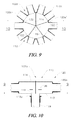
- FIG. 9 is an enlarged cross-sectional view of the upper spider diffuser system of FIG. 1 , which view is taken essentially along the line 9 - 9 of FIG. 10 ;
- FIG. 10 is a cross-sectional view of the upper spider diffuser system of FIG. 1 , which view is taken essentially along the line 10 - 10 of FIG. 9 ;
- FIG. 11 is an enlarged side elevational view of a pipe leg of the upper spider diffuser system of FIG. 1 ;
- FIG. 12 is a enlarged cross-sectional view of the pipe leg taken along the line 12 - 12 of FIG. 11 .
- FIG. 13 is a cross-sectional view of the pipe leg taken along the line 13 - 13 of FIG. 12 ;
- FIG. 14 is a cross-sectional view of the pipe leg taken along the line 14 - 14 of FIG. 11 ;
- FIG. 15A is a schematic view of a prior art TES operation showing the characteristic position of the thermocline during off-peak hours
- FIG. 15B is a schematic view of a prior art TES operation showing the characteristic position of the thermocline during peak hours.
- FIG. 16 is a graph that plots the exit velocities for water exiting the leg and entering the space in the tank via the slots.
- the abscissa of the graph plots the slot numbers with the highest number representing the slot that is farthest from the manifold structure.
- FIG. 1 A spider diffuser system assemblage for use in a TES tank 100 (See FIG. 3 .) and which embodies the principles and concepts of the invention, is shown in FIG. 1 , where it is referred to broadly by the reference numeral 102 .
- a complete operational spider diffuser system assemblage 102 may include two spider diffuser systems 102 a and 162 b which are positioned in oppositely facing dispositions.
- the spider diffuser systems 102 a and 102 b may be identical, so only the upper system 102 a will be described in detail herein. In accordance with the broader aspects of the invention, however, these systems do not necessarily need to be identical.
- tank 100 has a peripheral wall 104 having a generally cylindrical inner surface 106 surrounding a hollow internal space 108 .
- Tank 100 may be constructed of any of a multitude of materials commonly known and used in the liquid storage and containment field.
- tank 100 may be a prestressed concrete tank of the sort well known to those of ordinary skill in the field of fluid storage.
- either of the systems 102 a , 102 b may be used for introducing a temperature stratifiable liquid 109 into TES tank 100 , in which case the other of the systems 102 a , 102 b will be used for collecting and discharging the temperature stratifiable liquid from tank 100 .
- the spider diffuser system assemblage 102 may be installed in the tank 100 , essentially as shown in FIGS. 3 and 4 .
- the upper spider diffuser system 102 a may be disposed at approximately the same height as the junction 105 between the dome 103 and the wall 104 of tank 100 .
- the lower spider diffuser system 102 b may be disposed as close to floor 107 of tank 100 as may be practical from a tank construction and operation viewpoint.
- the exact vertical positioning of the upper and lower spider diffuser systems is a function of the unique design of each installation, and in general the position will be determined empirically.
- the assemblage 102 may be constructed of any one of a myriad of materials, including fiberglass, steel, polyvinyl chloride (PVC) and/or stainless steel. Moreover, the separate components of assemblage 102 may be made of the same or different materials. A much preferred material, however, is carbon steel for all components.
- Spider diffuser system 102 a comprises a manifold structure 110 arranged for being disposed in space 108 in vertically spaced relationship above a thermocline formed in temperature stratifiable liquid 109 in space 108 during operation of TES tank 100 .
- manifold structure 111 of system 102 b may be arranged for being disposed in space 108 in vertically spaced relationship below the thermocline. That is to say, the thermocline is always disposed between the spider diffuser systems 102 a , 102 b.
- TES processes may be adapted for use with a variety of different temperature stratifiable liquids.
- the liquid is water.
- Manifold structure 110 has a bottom plate 113 , a cover 114 and an internal chamber 115 . There is an opening 118 in bottom plate 113 (See FIG. 9 ) serving for introduction of water into chamber 115 or for discharge of water from chamber 115 . Ideally, there may be a short stub 118 a of piping connected to structure 110 at opening 118 to facilitate attachment of service piping 119 to opening 118 . Stub 118 a preferably may have an inside diameter that is the same size and shape as opening 118 and may be attached to the bottom plate 113 using a bolted flange or the like (not shown) or by welding. The height of structure 110 is generally not a critical design consideration.
- System 102 a also includes a diffuser pipe assembly 120 comprising a plurality of diffuser legs 120 a .
- Each diffuser leg 120 a is attached to manifold structure 110 so as to extend generally outwardly therefrom through space 108 , and toward inner surface 106 .
- diffuser legs 120 a may extend generally radially outwardly from manifold structure 110 , as shown with particularity in FIGS. 1 and 4 .
- manifold structure 110 may desirably have a generally decagonal horizontal cross-sectional configuration and a peripheral wall 128 made up of ten upright wall segments 130 . Segments 130 may desirably be joined together by welding.
- the structure 110 might just as well have any number of substitute cross-sectional shapes, such as, for example, octagonal, triangular, cylindrical, rectangular, etc.
- the wall 128 has opposed corners 128 a , and 128 b . These corners 128 a , 128 b are spaced apart across chamber 115 to present the largest horizontal dimension of manifold structure 110 .
- Structure 110 may include an internal baffle arrangement 131 disposed in chamber 115 .
- Arrangement 131 preferably may include five partitions 132 dividing internal chamber 115 into five separate chamber sections 134 . As can be seen in FIG. 6 , chamber sections 134 are each bounded by two partitions 132 and two segments 130 .
- arrangement 131 may further include a horizontally deposed disc baffle element 136 supported in corresponding slots 138 in partitions 132 .
- a flange 120 a ′ is provided for securing leg 120 a to a corresponding segment 130 of wall 128 .
- each segment 130 may be about 0.25′′ to 4′′ larger than the outside diameter of flange 120 a ′ of radial diffuser leg 120 a .
- the horizontal dimension of each segment 130 in a direction around the periphery of manifold structure 110 may be the same as the vertical dimension thereof such that the segments 130 are square.
- each of the diffuser legs 120 a has an elongated internal channel 122 that is in fluid communication with chamber 115 .
- the diffuser legs 120 a ideally are all the same, so when reference to a singular diffuser leg 120 a is made, such reference will apply equally to the other diffuser legs 120 a .
- Each diffuser leg 120 a has a plurality of slotted apertures 124 extending through the wall of diffuser leg 126 . Apertures 124 are distributed along the length of diffuser leg 120 a so as to intercommunicate channel 122 with space 108 . As can best be seen in FIG.
- spider diffuser system 102 a has ten diffuser legs 120 a , one for each segment 130 of the wall 128 . If the design characteristics of the TES process mandate, diffuser legs 120 a of differing numbers and/or alternating lengths might be called for.
- each diffuser leg 120 a is essentially the same as the ID of pipe stub 118 a , whereby the flow rate of the water entering chamber 115 via opening 118 is essentially ten times the flow rate of the water entering each diffuser leg 120 a from chamber 115 .
- the arrangement of the manifold structure 110 is such that the water entering each diffuser leg 120 a has a velocity of no more than about 1 ft/sec.
- a TES operation may be conducted using equipment as described above and the following process parameters and structural dimensions.
- Width of Manifold Structure 110 75 in between opposite corners 128a, 128b Number of upright wall segments 130 10 Number of Diffuser Legs 120a 10 Length of each Diffuser Leg 120a 27 ft ID of Each Diffuser Leg 120a 18.743 in OD of Each Diffuser Leg 120a 20 in Flow Rate of Water into Each Diffuser Leg 120a 775 gpm Maximum Fluid Velocity in Diffuser Legs 120 ⁇ 1.0 ft/sec Maximum Flow Velocity into Chamber 110 10 ft/sec Diffuser Pressure Drop 0.9365 psi
- FIG. 16 plots the exit velocities for water exiting leg 120 a and entering space 108 in tank 100 via slots 138 .
- the abscissa plots the slot numbers with the highest number representing the slot 138 that is farthest from manifold structure 110 .
- thermocline having a thickness of one to three feet between the warm and cold water may be developed and maintained during the charge and discharge cycles and throughout normal commercial operations.
Landscapes
- Engineering & Computer Science (AREA)
- General Engineering & Computer Science (AREA)
- Mechanical Engineering (AREA)
- Physics & Mathematics (AREA)
- Thermal Sciences (AREA)
- Life Sciences & Earth Sciences (AREA)
- Sustainable Development (AREA)
- Sustainable Energy (AREA)
- Chemical & Material Sciences (AREA)
- Combustion & Propulsion (AREA)
- Fluid Mechanics (AREA)
- Filling Or Discharging Of Gas Storage Vessels (AREA)
Priority Applications (1)
| Application Number | Priority Date | Filing Date | Title |
|---|---|---|---|
| US15/053,427 US9618277B2 (en) | 2013-03-14 | 2016-02-25 | Spider diffuser system |
Applications Claiming Priority (1)
| Application Number | Priority Date | Filing Date | Title |
|---|---|---|---|
| PCT/US2013/031561 WO2014142902A1 (fr) | 2013-03-14 | 2013-03-14 | Système de diffuseur à croisillon |
Related Parent Applications (1)
| Application Number | Title | Priority Date | Filing Date |
|---|---|---|---|
| PCT/US2013/031561 A-371-Of-International WO2014142902A1 (fr) | 2013-03-14 | 2013-03-14 | Système de diffuseur à croisillon |
Related Child Applications (1)
| Application Number | Title | Priority Date | Filing Date |
|---|---|---|---|
| US15/053,427 Continuation US9618277B2 (en) | 2013-03-14 | 2016-02-25 | Spider diffuser system |
Publications (2)
| Publication Number | Publication Date |
|---|---|
| US20150122356A1 US20150122356A1 (en) | 2015-05-07 |
| US9316445B2 true US9316445B2 (en) | 2016-04-19 |
Family
ID=51537289
Family Applications (2)
| Application Number | Title | Priority Date | Filing Date |
|---|---|---|---|
| US14/004,767 Active US9316445B2 (en) | 2013-03-14 | 2013-03-14 | Spider diffuser system |
| US15/053,427 Active US9618277B2 (en) | 2013-03-14 | 2016-02-25 | Spider diffuser system |
Family Applications After (1)
| Application Number | Title | Priority Date | Filing Date |
|---|---|---|---|
| US15/053,427 Active US9618277B2 (en) | 2013-03-14 | 2016-02-25 | Spider diffuser system |
Country Status (2)
| Country | Link |
|---|---|
| US (2) | US9316445B2 (fr) |
| WO (1) | WO2014142902A1 (fr) |
Cited By (3)
| Publication number | Priority date | Publication date | Assignee | Title |
|---|---|---|---|---|
| US9618277B2 (en) * | 2013-03-14 | 2017-04-11 | Crom, Llc | Spider diffuser system |
| US11124927B1 (en) | 2020-04-16 | 2021-09-21 | Crom, Llc | Overflow spout for tank |
| US11662157B1 (en) | 2020-08-29 | 2023-05-30 | Joseph R. Kucic | Thermal energy storage tank diaphragm system |
Families Citing this family (3)
| Publication number | Priority date | Publication date | Assignee | Title |
|---|---|---|---|---|
| DE102015104909B3 (de) * | 2015-03-30 | 2016-09-29 | MBS Naturstromspeicher GmbH | Energiespeicher, Kraftwerksanlage mit Energiespeicher und Verfahren zum Betrieb desselben |
| DE102016010270A1 (de) * | 2016-08-24 | 2018-03-01 | Gerald Funck | Verfahren und Vorrichtung zur Verteilung körnigen Guts auf mehrere Leitungen |
| US10743462B2 (en) * | 2019-01-11 | 2020-08-18 | Cnh Industrial America Llc | Flow splitter for distributing agricultural products and related system |
Citations (21)
| Publication number | Priority date | Publication date | Assignee | Title |
|---|---|---|---|---|
| US4643212A (en) | 1984-03-28 | 1987-02-17 | Chicago Bridge & Iron Company | Hot liquid thermal energy storage tank and method |
| US4987922A (en) | 1989-04-20 | 1991-01-29 | Chicago Bridge & Iron Technical Services Company | Storage tank for two fluids of different density |
| US5103863A (en) | 1989-12-12 | 1992-04-14 | Conoco Inc. | Inlet distributors and outlet collectors that are rate insensitive |
| US5137053A (en) | 1991-07-25 | 1992-08-11 | Kale Hemant D | Storage tank for water heaters and the like with diffuser inlet |
| US5176161A (en) | 1991-12-02 | 1993-01-05 | Chicago Bridge & Iron Technical Services Company | Apparatus and method for controlled flow distribution |
| US5181537A (en) * | 1989-12-12 | 1993-01-26 | Conoco Inc. | Outlet collectors that are rate insensitive |
| US5197513A (en) | 1992-04-03 | 1993-03-30 | San Luis Tank Piping Construction Co. Inc. | Stratified chamber system for receiving, storing and dispensing two different density liquids |
| US5381860A (en) * | 1993-09-28 | 1995-01-17 | Dirrecktor Tes Systems, Inc. | Thermal energy storage system for a cool water air conditioning system |
| US5386871A (en) | 1992-11-24 | 1995-02-07 | Abb Lummus Crest Inc. | Thermal energy storage and recovery system |
| US6290433B2 (en) * | 1998-02-06 | 2001-09-18 | Flexi-Coil Ltd. | Distribution system for conveying air-entrained material |
| US6318065B1 (en) * | 1999-08-06 | 2001-11-20 | Tom L. Pierson | System for chilling inlet air for gas turbines |
| JP2004053140A (ja) | 2002-07-19 | 2004-02-19 | Taisei Corp | 温度成層型蓄熱装置 |
| US6920984B2 (en) | 2002-12-06 | 2005-07-26 | Warren Roy Agnew | Rainwater tank cleaning system |
| US6994111B2 (en) | 2001-12-21 | 2006-02-07 | Amalgamated Research, Inc. | Toroidal vessel for uniform, plug-flow fluid distribution applications |
| US7069975B1 (en) | 1999-09-16 | 2006-07-04 | Raytheon Company | Method and apparatus for cooling with a phase change material and heat pipes |
| US20080115918A1 (en) | 2004-08-24 | 2008-05-22 | Christiane Kerber | Rolled Heat Exchange |
| US20090056814A1 (en) | 2007-08-27 | 2009-03-05 | Rohde Uwe | Method and device for storing chemical products in a container |
| US20100025031A1 (en) | 2006-12-31 | 2010-02-04 | Beijing Poweru Technology Co., Ltd. | Multiple tanks water thermal storage system and its using method |
| US20110168159A1 (en) | 2008-07-01 | 2011-07-14 | Sener Ingenieria Y Sistemas, S.A. | Dual thermal energy storage tank |
| US20110271953A1 (en) | 2010-05-04 | 2011-11-10 | Basf Se | Device and method for storing heat |
| US20130023044A1 (en) * | 2011-07-19 | 2013-01-24 | Cornel Gleason | System and Method for Fuel Generation from Algae |
Family Cites Families (1)
| Publication number | Priority date | Publication date | Assignee | Title |
|---|---|---|---|---|
| WO2014142902A1 (fr) * | 2013-03-14 | 2014-09-18 | The Crom Corporation | Système de diffuseur à croisillon |
-
2013
- 2013-03-14 WO PCT/US2013/031561 patent/WO2014142902A1/fr not_active Ceased
- 2013-03-14 US US14/004,767 patent/US9316445B2/en active Active
-
2016
- 2016-02-25 US US15/053,427 patent/US9618277B2/en active Active
Patent Citations (21)
| Publication number | Priority date | Publication date | Assignee | Title |
|---|---|---|---|---|
| US4643212A (en) | 1984-03-28 | 1987-02-17 | Chicago Bridge & Iron Company | Hot liquid thermal energy storage tank and method |
| US4987922A (en) | 1989-04-20 | 1991-01-29 | Chicago Bridge & Iron Technical Services Company | Storage tank for two fluids of different density |
| US5103863A (en) | 1989-12-12 | 1992-04-14 | Conoco Inc. | Inlet distributors and outlet collectors that are rate insensitive |
| US5181537A (en) * | 1989-12-12 | 1993-01-26 | Conoco Inc. | Outlet collectors that are rate insensitive |
| US5137053A (en) | 1991-07-25 | 1992-08-11 | Kale Hemant D | Storage tank for water heaters and the like with diffuser inlet |
| US5176161A (en) | 1991-12-02 | 1993-01-05 | Chicago Bridge & Iron Technical Services Company | Apparatus and method for controlled flow distribution |
| US5197513A (en) | 1992-04-03 | 1993-03-30 | San Luis Tank Piping Construction Co. Inc. | Stratified chamber system for receiving, storing and dispensing two different density liquids |
| US5386871A (en) | 1992-11-24 | 1995-02-07 | Abb Lummus Crest Inc. | Thermal energy storage and recovery system |
| US5381860A (en) * | 1993-09-28 | 1995-01-17 | Dirrecktor Tes Systems, Inc. | Thermal energy storage system for a cool water air conditioning system |
| US6290433B2 (en) * | 1998-02-06 | 2001-09-18 | Flexi-Coil Ltd. | Distribution system for conveying air-entrained material |
| US6318065B1 (en) * | 1999-08-06 | 2001-11-20 | Tom L. Pierson | System for chilling inlet air for gas turbines |
| US7069975B1 (en) | 1999-09-16 | 2006-07-04 | Raytheon Company | Method and apparatus for cooling with a phase change material and heat pipes |
| US6994111B2 (en) | 2001-12-21 | 2006-02-07 | Amalgamated Research, Inc. | Toroidal vessel for uniform, plug-flow fluid distribution applications |
| JP2004053140A (ja) | 2002-07-19 | 2004-02-19 | Taisei Corp | 温度成層型蓄熱装置 |
| US6920984B2 (en) | 2002-12-06 | 2005-07-26 | Warren Roy Agnew | Rainwater tank cleaning system |
| US20080115918A1 (en) | 2004-08-24 | 2008-05-22 | Christiane Kerber | Rolled Heat Exchange |
| US20100025031A1 (en) | 2006-12-31 | 2010-02-04 | Beijing Poweru Technology Co., Ltd. | Multiple tanks water thermal storage system and its using method |
| US20090056814A1 (en) | 2007-08-27 | 2009-03-05 | Rohde Uwe | Method and device for storing chemical products in a container |
| US20110168159A1 (en) | 2008-07-01 | 2011-07-14 | Sener Ingenieria Y Sistemas, S.A. | Dual thermal energy storage tank |
| US20110271953A1 (en) | 2010-05-04 | 2011-11-10 | Basf Se | Device and method for storing heat |
| US20130023044A1 (en) * | 2011-07-19 | 2013-01-24 | Cornel Gleason | System and Method for Fuel Generation from Algae |
Cited By (3)
| Publication number | Priority date | Publication date | Assignee | Title |
|---|---|---|---|---|
| US9618277B2 (en) * | 2013-03-14 | 2017-04-11 | Crom, Llc | Spider diffuser system |
| US11124927B1 (en) | 2020-04-16 | 2021-09-21 | Crom, Llc | Overflow spout for tank |
| US11662157B1 (en) | 2020-08-29 | 2023-05-30 | Joseph R. Kucic | Thermal energy storage tank diaphragm system |
Also Published As
| Publication number | Publication date |
|---|---|
| US20150122356A1 (en) | 2015-05-07 |
| US20160169592A1 (en) | 2016-06-16 |
| US9618277B2 (en) | 2017-04-11 |
| WO2014142902A1 (fr) | 2014-09-18 |
Similar Documents
| Publication | Publication Date | Title |
|---|---|---|
| US9618277B2 (en) | Spider diffuser system | |
| US9511382B2 (en) | Nozzle for distribution of a fluid | |
| CN202709399U (zh) | 一种环形均流布水装置 | |
| JP7477180B2 (ja) | 蓄熱容器内の流体の流れ | |
| EP3249332B1 (fr) | Appareil d'amenée amélioré pour tour d'échange de chaleur modulaire | |
| CN107356017A (zh) | 降膜式蒸发器用布液器 | |
| EP2698584B1 (fr) | Accumulateur sans pression pour systèmes de chauffage urbain | |
| CN218242075U (zh) | 储能电池柜和具有其的储能系统 | |
| US5381860A (en) | Thermal energy storage system for a cool water air conditioning system | |
| CN103807959A (zh) | 条缝式均流布水管、条缝式均流布水器及水蓄冷设备 | |
| CN201093647Y (zh) | 分配散流管同程建模自然分层水蓄冷装置 | |
| EP0414834B1 (fr) | Appareil thermique a accumulation | |
| US9227781B1 (en) | Storage tanks using super ellipse geometries | |
| CN204739712U (zh) | 温度分层水蓄冷装置 | |
| CN220322164U (zh) | 一种蓄能水罐均流布水器和布水器装置 | |
| CN210004838U (zh) | 方形水池的布水器和方形水池 | |
| CN216143998U (zh) | 一种承压式谷电蓄热装置 | |
| CN207456260U (zh) | 一种适用于摇晃工况的板翅式换热器封头 | |
| CN112414161B (zh) | 湿式冷却塔 | |
| CN203719009U (zh) | 条缝式均流布水管、条缝式均流布水器及水蓄冷设备 | |
| CN210404387U (zh) | 一种具有节能降温结构的电力开关柜 | |
| CN224051092U (zh) | 一种新型石墨急冷塔 | |
| CN107975894B (zh) | 用于蓄冷罐的布水器及开孔与安装方法 | |
| CN214746162U (zh) | 一种相变材料蓄冷设备 | |
| CN221992500U (zh) | 一种具备储释能反向特性的蓄热蓄冷一体储能水箱 |
Legal Events
| Date | Code | Title | Description |
|---|---|---|---|
| AS | Assignment |
Owner name: THE CROM CORPORATION, FLORIDA Free format text: ASSIGNMENT OF ASSIGNORS INTEREST;ASSIGNOR:MINCEY, CHRISTOPHER TALMADGE;REEL/FRAME:031404/0692 Effective date: 20131011 |
|
| FEPP | Fee payment procedure |
Free format text: PETITION RELATED TO MAINTENANCE FEES GRANTED (ORIGINAL EVENT CODE: PTGR); ENTITY STATUS OF PATENT OWNER: SMALL ENTITY |
|
| AS | Assignment |
Owner name: CROM, LLC, FLORIDA Free format text: CONVERSION OF CORPORATION INTO LIMITED LIABILITY COMPANY;ASSIGNOR:THE CROM CORPORATION;REEL/FRAME:033987/0455 Effective date: 20141006 |
|
| STCF | Information on status: patent grant |
Free format text: PATENTED CASE |
|
| CC | Certificate of correction | ||
| MAFP | Maintenance fee payment |
Free format text: PAYMENT OF MAINTENANCE FEE, 4TH YR, SMALL ENTITY (ORIGINAL EVENT CODE: M2551); ENTITY STATUS OF PATENT OWNER: SMALL ENTITY Year of fee payment: 4 |
|
| AS | Assignment |
Owner name: TRUIST BANK, GEORGIA Free format text: SECURITY INTEREST;ASSIGNOR:CROM, LLC;REEL/FRAME:052886/0206 Effective date: 20200605 |
|
| MAFP | Maintenance fee payment |
Free format text: PAYMENT OF MAINTENANCE FEE, 8TH YR, SMALL ENTITY (ORIGINAL EVENT CODE: M2552); ENTITY STATUS OF PATENT OWNER: SMALL ENTITY Year of fee payment: 8 |
|
| AS | Assignment |
Owner name: WHITEHORSE CAPITAL ORIGINATION, LLC, FLORIDA Free format text: SECURITY INTEREST;ASSIGNOR:CROM, LLC;REEL/FRAME:070071/0451 Effective date: 20250131 |
|
| AS | Assignment |
Owner name: CROM, LLC, FLORIDA Free format text: TERMINATION AND RELEASE OF PATENT SECURITY AGREEMENT;ASSIGNOR:TRUIST BANK;REEL/FRAME:070110/0725 Effective date: 20250131 |