US9328439B2 - Electromagnetic actuator, particularly for needle selection devices in machines for knitting, hosiery or the like, with high gauge - Google Patents
Electromagnetic actuator, particularly for needle selection devices in machines for knitting, hosiery or the like, with high gauge Download PDFInfo
- Publication number
- US9328439B2 US9328439B2 US14/409,585 US201314409585A US9328439B2 US 9328439 B2 US9328439 B2 US 9328439B2 US 201314409585 A US201314409585 A US 201314409585A US 9328439 B2 US9328439 B2 US 9328439B2
- Authority
- US
- United States
- Prior art keywords
- selection
- polar
- electromagnet
- main magnet
- polar region
- Prior art date
- Legal status (The legal status is an assumption and is not a legal conclusion. Google has not performed a legal analysis and makes no representation as to the accuracy of the status listed.)
- Expired - Fee Related
Links
Images


Classifications
-
- D—TEXTILES; PAPER
- D04—BRAIDING; LACE-MAKING; KNITTING; TRIMMINGS; NON-WOVEN FABRICS
- D04B—KNITTING
- D04B15/00—Details of, or auxiliary devices incorporated in, weft knitting machines, restricted to machines of this kind
- D04B15/66—Devices for determining or controlling patterns ; Program-control arrangements
- D04B15/68—Devices for determining or controlling patterns ; Program-control arrangements characterised by the knitting instruments used
- D04B15/78—Electrical devices
Definitions
- the present invention relates to an electromagnetic actuator, particularly for needle selection devices in machines for knitting, hosiery or the like, with high gauge.
- Electromagnetic actuators for needle selection devices in machines for knitting, hosiery or the like are known.
- These electromagnetic actuators are generally composed substantially of a main magnet, which has two side-by-side polar regions separated by a gap, and a selection electromagnet, which is provided with a ferromagnetic core that has at least one polar region arranged at the gap between the two polar regions of the main magnet.
- the selection electromagnet is provided with a coil that can be supplied with electric power in order to cancel or reduce substantially the attractive magnetic force of the polar region of the core of the selection electromagnet induced by the main magnet.
- Needle selection devices that use these electromagnetic actuators generally comprise a plurality of selection elements that are made of a material that is susceptible of magnetic attraction, can move with respect to the electromagnetic actuator along an activation direction and, in their motion, face the polar regions of the main magnet and of the core of the selection electromagnet.
- the electromagnetic actuator is arranged on the machine so that the polar regions are arranged sequentially along the direction of activation of the selection elements so that they, in their motion along the activation direction, face in succession with one of their sides first one of the polar regions of the main magnet, then the gap and the polar region of the core of the selection electromagnet and finally the other polar region of the main magnet.
- the selection elements can move from a first position, in which they are adjacent or even in contact with the above-cited polar regions, to a second position, in which they are spaced from the polar regions with respect to the first position.
- This mobility of the selection elements in the two positions corresponds to two different activations of the elements of the machine, generally needles, that must be selected by means of the selection device.
- an abutment constituted generally by a cam, operates on the selection elements so that they all pass into the first position just before or at the first polar region of the main magnet that retains the selection elements in this position until the gap begins.
- the attractive force of the selection electromagnet core, produced by the main magnet is canceled or substantially reduced to such an extent that it is insufficient to contrast the force of the elastic element that makes the selection element pass into the second position, in which it remains even during the passage at the second polar region of the main magnet, the attractive force of which is in itself insufficient to cause the passage of the selection element from the second position to the first position.
- the selection electromagnet core retains in the first position the selection element, which remains in this position and is retained in said first position also during the passage at the second polar region of the main magnet.
- the selection element depending on whether it is in the first position or in the second position, with consequent engagement or lack thereof with other elements of the machine, causes a different actuation of the element, generally a needle, of the machine that is correlated therewith, obtaining the desired selection.
- the sizing and power supply of the selection electromagnet coil in electromagnetic actuators of the known type are complicated, since the intensity of the magnetic field induced at the polar region of the selection electromagnet, and therefore the attraction force exerted by this polar region on the selection element, vary as a function of the number of selection elements that are in contact with or adjacent to the polar regions of the main magnet, since the selection elements produce, through their presence, a variation of the magnetic field of the main magnet, which in turn causes variations of the magnetic field induced in the selection electromagnet core that is arranged inside the main magnet, at the gap, between its polar regions.
- Italian patent no. 1,357,140 in the name of the same Applicant describes an electromagnetic actuator that solves the problems described above due to the fact that the selection electromagnet has at least one polar region that is aligned with the gap of the two polar regions of the main magnet and is spaced laterally from said gap.
- the dimension of the polar region of the selection electromagnet in alignment with the gap of the main magnet, along the direction of actuation of the selection elements with respect to the electromagnetic actuator in fact must not be too wide; in particular, it must be smaller than or equal to the distance between two contiguous selection elements, because otherwise the selection electromagnet, by means of its polar region, would act simultaneously on two contiguous selection elements and therefore would be unable to actuate two contiguous selection elements differently.
- the aim of the present invention is to solve the problem described above, providing an electromagnetic actuator for needle selection devices in machines for knitting, hosiery or the like that allows correct actuation of the selection elements even in case of high gauges and with high actuation speeds of the selection elements with respect to the electromagnetic actuator.
- an object of the present invention is to provide an electromagnetic actuator that is highly reliable in operation.
- Another object of the invention is to provide an electromagnetic actuator that has a limited space occupation.
- a further object of the invention is to provide an electromagnetic actuator that retains the advantages of the electromagnetic actuator according to Italian patent no. 1,357,140 in terms of manufacturing and actuation simplicity.
- an electromagnetic actuator particularly for needle selection devices in machines for knitting, hosiery or the like, with high gauge, comprising a main magnet which has at least two polar regions which are side-by-side and separated by a gap, characterized in that it comprises two selection electromagnets, each one provided with at least one polar region which is aligned with said gap and spaced laterally from said gap, the at least one polar region of a selection electromagnet of said two selection electromagnets being arranged laterally on the side opposite to the at least one polar region of the other selection electromagnet of said two selection electromagnets with respect to said gap, said selection electromagnets being able to be activated individually to generate or cancel or reduce an attractive magnetic force at the corresponding polar region.
- FIG. 1 is a perspective view of the actuator according to the invention which faces a plurality of selection elements of a needle selection device of a circular knitting machine, which are shown only partially for the sake of simplicity;
- FIG. 2 is a view, similar to FIG. 1 , of the actuator according to the invention, showing a selection element
- FIG. 3 is a view, similar to FIG. 1 , of the actuator according to the invention, showing another selection element;
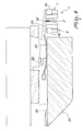
- FIG. 4 is a lateral elevation view of the electromagnetic actuator according to the invention, applied to a needle selection device of the dial of a circular knitting machine, showing a selection element in a first position;
- FIG. 5 is a lateral elevation view of the electromagnetic actuator according to the invention, applied to a needle selection device of the dial of a circular knitting machine, showing the selection element of FIG. 4 in a second position;
- FIG. 6 is a lateral elevation view of the electromagnetic actuator according to the invention, applied to a needle selection device of the dial of a circular knitting machine, showing another selection element in a first position;
- FIG. 7 is a lateral elevation view of the electromagnetic actuator according to the invention, applied to a needle selection device of the dial of a circular knitting machine, showing the selection element of FIG. 6 in a second position;
- FIG. 8 is a schematic sectional view of FIG. 4 along the plane VIII-VIII, showing a plurality of selection elements
- FIGS. 9 to 11 are schematic views of an actuation sequence of a selection element with the electromagnetic actuator according to the invention shown in a front elevation view;
- FIGS. 12 to 14 are schematic views of another actuation sequence of a selection element with the electromagnetic actuator according to the invention in a front elevation view.
- the electromagnetic actuator according to the invention comprises a main magnet 2 , which has at least two polar regions 3 a , 4 a , 3 b , 4 b that are arranged side by side and separated by a gap 5 a , 5 b.
- the electromagnetic actuator also comprises two selection electromagnets 6 , 7 , each one provided with at least one polar region 6 a , 6 b , 7 a , 7 b that is aligned with the gap 5 a , 5 b of the main magnet 2 and is spaced laterally from said gap 5 a , 5 b .
- the at least one polar region 6 a , 6 b of the selection electromagnet 6 is arranged laterally on the side opposite to the at least one polar region 7 a , 7 b of the other selection electromagnet 7 with respect to the gap 5 a , 5 b of the main magnet 2 .
- the selection electromagnets 6 , 7 can be actuated individually in order to generate or cancel or reduce an attractive magnetic force at the corresponding polar region 6 a , 6 b , 7 a , 7 b , as will become more apparent hereinafter.
- the selection electromagnets 6 , 7 are spaced laterally from the main magnet 2 so that the gap 5 a , 5 b of the main magnet 2 is completely free from the polar regions of selection electromagnets.
- the main magnet 2 in the illustrated embodiment, comprises a permanent magnet 8 , which is enclosed in a sandwich-like fashion between two yokes 9 a , 9 b , which form, with their ends, two pairs of polar regions, respectively a first pair of polar regions 3 a , 3 b and a second pair of polar regions 4 a , 4 b , in which the polar regions 3 a , 4 a are formed by the yoke 9 a and the polar regions 3 b , 4 b are formed by the yoke 9 b .
- the polar regions 3 a , 4 a of the yoke 9 a are separated by a corresponding gap 5 a
- the polar regions 3 b , 4 b of the yoke 9 b are separated by a corresponding gap 5 b.
- Each one of the two yokes 9 a , 9 b of the main magnet 2 is substantially U-shaped, with the corresponding gap 5 a , 5 b formed between the two free ends of the U-shape.
- the permanent magnet 8 of the main magnet 2 is interposed between the two yokes 9 a , 9 b proximate to the region at which the two arms of each U-shape of the two yokes 9 a , 9 b join.
- the main magnet 2 can be provided with a single yoke and therefore with a single gap instead of two mutually aligned gaps as shown.
- Each selection electromagnet 6 , 7 comprises a permanent magnet 10 , 11 , which is enclosed in a sandwich-like fashion between two mutually parallel bars 12 a , 12 b , 13 a , 13 b , which form, with one of their ends, two polar regions 6 a , 6 b , 7 a , 7 b , which are aligned with each other and with the gaps 5 a , 5 b of the main magnet 2 .
- the two bars 12 a , 12 b , 13 a , 13 b are made of ferromagnetic material, so that by the effect of the permanent magnet 10 , 11 , an attractive force is generated, at the polar regions 6 a , 6 b , 7 a , 7 b , on a body made of ferromagnetic material that faces said polar regions 6 a , 6 b , 7 a , 7 b .
- Each selection electromagnet 6 , 7 comprises an actuation coil 14 , 15 , which can be supplied with electric power for cancellation or reduction of the attractive magnetic force at the polar regions 6 a , 6 b , 7 a , 7 b.
- each selection electromagnet 6 , 7 are arranged side-by-side along a direction 16 that is substantially perpendicular to the direction of side-by-side arrangement 17 of the two polar regions 3 a , 4 a and 3 b , 4 b of the pairs of polar regions of the main magnet 2 .
- the polar regions 6 a , 6 b , 7 a , 7 b of the selection electromagnets 6 , 7 are all mutually aligned along a direction 16 that is perpendicular to the direction of side-by-side arrangement 17 of the two polar regions 3 a , 4 a and 3 b , 4 b of the pairs of polar regions of the main magnet 2 between which the gaps 5 a , 5 b , also aligned along the direction 16 , are formed.
- each selection electromagnet 6 , 7 the corresponding control coil 14 , 15 is arranged around one of the two bars 12 a , 12 b , 13 a , 13 b that form the two polar regions 6 a , 6 b , 7 a , 7 b of the corresponding selection electromagnet 6 , 7 .
- the control coil 14 of the selection electromagnet 6 is arranged around the bar 12 a
- the control coil 15 of the selection electromagnet 7 is arranged around the bar 13 a.
- the electromagnetic actuator according to the invention is intended to be used preferably in needle selection devices for machines for knitting, hosiery or the like, with the two polar regions or the two pairs of polar regions 3 a , 4 a , 3 b , 4 b of the main magnet 2 arranged in sequence, in a substantially coplanar position, along an actuation direction, designated by the arrow 18 , so that they face selection elements 22 , 23 that are made of a material susceptible to magnetic attraction and can move along said actuation direction 18 with respect to the electromagnetic actuator 1 .
- the selection elements 22 , 23 face sequentially a first polar region or a first pair of polar regions 3 a , 3 b of the main magnet 2 , then the gap 5 a , 5 b and the two polar regions 6 a , 6 b of a selection electromagnet 6 or the two polar regions 7 a , 7 b of the other selection electromagnet 7 and then a second polar region or a second pair of polar regions 4 a , 4 b of the main magnet 2 .
- the selection elements 22 , 23 comprise first selection elements 22 , which are adapted to interact with the polar regions 3 a , 3 b , 4 a , 4 b of the main magnet 2 and with the two polar regions 6 a , 6 b of the selection electromagnet 6 , and second selection elements 23 , which are adapted to interact with the polar regions 3 a , 3 b , 4 a , 4 b of the main magnet 2 and with the two polar regions 7 a , 7 b of the other selection electromagnet 7 .
- the first selection elements 22 are shorter than the second selection elements 23 , which, thanks to their greater length, bypass the selection electromagnet 6 intended to interact with the first selection elements 22 and face the other selection electromagnet 7 intended to interact with them.
- the selection elements 22 , 23 are arranged so that in each instance, as a consequence of movement imparted to the selection elements 22 , 23 with respect to the electromagnetic actuator 1 according to the invention, the gap 5 a , 5 b of the main magnet 2 faces a first selection element 22 and then a second selection element 23 .
- the selection elements 22 , 23 are arranged so that the first selection elements 22 , which are shorter, are alternated with the second selection elements 23 , which are longer.
- the selection elements 22 , 23 can move from a first position, in which they are kept adjacent to the polar regions 3 a , 3 b , 6 a , 6 b , 7 a , 7 b , 4 a , 4 b by the magnetic attraction exerted by said polar regions, to a second position, in which they are further spaced from the polar regions 3 a , 3 b , 6 a , 6 b , 7 a , 7 b , 4 a , 4 b than in the first position.
- Each selection element 22 , 23 in order to pass from the first position to the second position and vice versa, can move on a plane that is perpendicular to the actuation direction 18 and the movement from the second position to the first position is contrasted by elastic means that can be constituted by a spring 24 .
- the electromagnetic actuator according to the invention can be used also with other types of needle selection devices, merely by way of example and only to further clarify its actuation, the operation of the electromagnetic actuator according to the invention is explained hereinafter with reference to a needle selection device 30 of the dial 31 of a circular knitting machine, similar to the one shown in Italian patent no. 1,293,789 in the name of the same Applicant, which uses, as selection elements 22 , 23 , levers which are pivoted, about a pivoting axis 32 , to the end of the corresponding needle 30 that is opposite to the tip and can oscillate about said pivoting axis 32 in order to pass from the first position to the second position and vice versa.
- 1,293,789 is provided with selection elements constituted by levers that have the same length, whereas the selection device shown in the accompanying drawings is provided with selection elements that are arranged so as to form alternately a first selection element 22 , constituted by a short lever, and a second selection element 23 , constituted by a long lever.
- each selection element 22 , 23 is moved along the actuation direction 18 with respect to the electromagnetic actuator 1 .
- an abutment constituted for example by a cam, acts on them, causing their passage from the second position to the first position, i.e., pushing them toward said polar regions 3 a , 3 b , which, as a consequence of their magnetic attraction, retain the selection elements 22 , 23 in the first position, as shown in FIGS. 9 and 12 .
- the control coil 14 is supplied with power, the attractive force of the polar regions 6 a , 6 b of the selection electromagnet 6 is canceled or reduced and the first selection element 22 passes, through the action of the spring 24 , to the second position, i.e., it moves away from the polar region, as shown in FIGS. 5 and 13 . Then, during passage at the second pair of polar regions 4 a , 4 b of the main magnet 2 , said first selection element 22 remains in the second position, as shown in FIG. 14 .
- the different position assumed by the selection element 22 , 23 , after the passage at the gap 5 a , 5 b of the polar regions 3 a , 3 b , 4 a , 4 b and of the selection electromagnets 6 , 7 is used for an engagement or disengagement of the selection element 22 , 23 with actuation elements, for example cams, so as to cause a different actuation of the needle 30 , to which the selection elements 22 , 23 is connected and which is thus selected by means of the device.
- actuation elements for example cams
- the electromagnetic actuator according to the invention can also be provided in other embodiments that are within the protective scope of the present invention, for example by provision of the selection electromagnets 6 , 7 with a simple core of ferromagnetic material instead of a permanent magnet. Regardless of the fact that the cores of the selection electromagnets 6 , 7 may also have other shapes, the selection electromagnets may also be provided substantially as described and illustrated with reference to the accompanying drawings, simply by replacement of the permanent magnets 10 , 11 described with reference to the above-cited drawings by ferromagnetic cores.
- the cores of the selection electromagnets 6 , 7 can be provided monolithically with the bars 12 a , 12 b , 13 a , 13 b of the corresponding selection electromagnet 6 , 7 .
- the operation of the electromagnetic actuator differs from the one described above in that when one wishes to keep a selection element 22 , 23 in the first position at the gap 5 a , 5 b of the main magnet 2 the control coil 14 , 15 of the selection electromagnet 6 , 7 is supplied with power so that an attractive force is generated at the polar regions 6 a , 6 b , 7 a , 7 b , whereas when one wishes to induce the passage of the selection element 22 , 23 from the first position to the second position the control coil 14 , 15 of the selection electromagnet 6 , 7 is not supplied with power.
- the faces of the polar regions 3 a , 3 b , 6 a , 6 b , 7 a , 7 b , 4 a , 4 b of the main magnet 2 and of the selection electromagnets 6 , 7 directed toward the selection elements 22 , 23 are substantially co-planar.
- the electromagnetic actuator according to the invention by means of the provision of two selection electromagnets 6 , 7 arranged laterally on mutually opposite sides with respect to the gap 5 a , 5 b of the main magnet 2 and by the use of selection elements 22 , 23 of different lengths which are mutually alternated and face respectively one and the other of the selection electromagnets 6 , 7 , in practice the space between the selection elements 22 , 23 that is available to operate with one or the other of the selection electromagnets 6 , 7 in practice is doubled.
- the electromagnetic actuator according to the invention it is possible to actuate in a different manner two contiguous selection elements 22 , 23 , i.e., keep one selection element 22 or 23 in the first position while the contiguous selection element 23 or 22 is moved to the second position or vice versa.
- the solution of using a single main magnet 2 with two selection electromagnets 6 , 7 has the advantage of a limited space occupation which simplifies the installation of the electromagnetic actuator on machines.
- the electromagnetic actuator according to the invention achieves fully the intended aim and objects, since it allows correct actuation of the selection elements even in the case of high gauges and with high actuation speeds of the selection elements with respect to the electromagnetic actuator.
- the materials used may be any according to the requirements and the state of the art.
Landscapes
- Engineering & Computer Science (AREA)
- Textile Engineering (AREA)
- Knitting Machines (AREA)
Applications Claiming Priority (4)
| Application Number | Priority Date | Filing Date | Title |
|---|---|---|---|
| ITMI2012A001091 | 2012-06-21 | ||
| IT001091A ITMI20121091A1 (it) | 2012-06-21 | 2012-06-21 | Attuatore elettromagnetico, particolarmente per dispositivi di selezione degli aghi in macchine per maglieria, calzetteria o simili, ad elevata finezza. |
| ITMI2012A1091 | 2012-06-21 | ||
| PCT/EP2013/062113 WO2013189797A1 (en) | 2012-06-21 | 2013-06-12 | Electromagnetic actuator, particularly for needle selection devices in machines for knitting, hosiery or the like, with high gauge |
Publications (2)
| Publication Number | Publication Date |
|---|---|
| US20150197880A1 US20150197880A1 (en) | 2015-07-16 |
| US9328439B2 true US9328439B2 (en) | 2016-05-03 |
Family
ID=46832901
Family Applications (1)
| Application Number | Title | Priority Date | Filing Date |
|---|---|---|---|
| US14/409,585 Expired - Fee Related US9328439B2 (en) | 2012-06-21 | 2013-06-12 | Electromagnetic actuator, particularly for needle selection devices in machines for knitting, hosiery or the like, with high gauge |
Country Status (8)
| Country | Link |
|---|---|
| US (1) | US9328439B2 (it) |
| EP (1) | EP2864533B1 (it) |
| KR (1) | KR102030098B1 (it) |
| CN (1) | CN104395516B (it) |
| BR (1) | BR112014031044B1 (it) |
| IT (1) | ITMI20121091A1 (it) |
| TW (1) | TWI591227B (it) |
| WO (1) | WO2013189797A1 (it) |
Cited By (3)
| Publication number | Priority date | Publication date | Assignee | Title |
|---|---|---|---|---|
| US20160122914A1 (en) * | 2013-06-21 | 2016-05-05 | Santoni S.P.A. | Thread dispensing element for a thread guide for knitting machines, and thread guide comprising the dispensing element |
| KR101897674B1 (ko) * | 2017-12-29 | 2018-09-12 | 윤대영 | 다신호 액츄에이터 |
| US20250003121A1 (en) * | 2021-10-08 | 2025-01-02 | Santoni S.P.A. | A drive chain for stitch formation members of a circular knitting machine and a circular knitting machine comprising such drive chain |
Families Citing this family (2)
| Publication number | Priority date | Publication date | Assignee | Title |
|---|---|---|---|---|
| JP7204624B2 (ja) * | 2019-09-30 | 2023-01-16 | 株式会社島精機製作所 | 給電機構付き装置 |
| IT202100025898A1 (it) * | 2021-10-08 | 2023-04-08 | Santoni & C Spa | Catena di trasmissione per organi di formazione maglia di una macchina circolare per maglieria e macchina circolare per maglieria comprendente tale catena di trasmissione |
Citations (9)
| Publication number | Priority date | Publication date | Assignee | Title |
|---|---|---|---|---|
| US4715198A (en) * | 1986-04-26 | 1987-12-29 | H. Stoll Gmbh & Co. | Control magnet assembly for a pattern apparatus in knitting machines for electrically controlled needle selection |
| EP0874077A2 (en) | 1997-04-01 | 1998-10-28 | Precision Fukuhara Works, Ltd | Jacquerd pattern control mechanism for a circular knitting machine |
| US6014875A (en) | 1997-07-25 | 2000-01-18 | Santoni S.P.A. | Needle selection device, particularly for selecting the dial needles in circular knitting machines |
| US6584810B2 (en) * | 2000-03-31 | 2003-07-01 | Shima Seiki Mfg., Ltd. | Knitting member selecting actuator of knitting machine |
| US6651464B2 (en) * | 2000-08-28 | 2003-11-25 | Shima Seiki Manufacturing Ltd. | Selector actuator for knitting members in a knitting machine |
| US6962065B2 (en) * | 2003-05-09 | 2005-11-08 | Sipra Patententwicklungs- Und Beteiligungsgesellschaft Mbh | Knitting machine, in particular circular knitting machine, and control jack suitable for same |
| EP1739218A1 (en) | 2004-03-30 | 2007-01-03 | Shima Seiki Manufacturing., Ltd. | Selection actuator for knitting member |
| EP2100991A1 (en) | 2006-11-28 | 2009-09-16 | Shima Seiki Manufacturing., Ltd. | Needle selecting actuator, and weft knitting machine |
| US7770417B2 (en) * | 2005-11-18 | 2010-08-10 | Santoni S.P.A. | Magnetic actuator, particularly for selection devices in hosiery knitting machines or the like |
Family Cites Families (2)
| Publication number | Priority date | Publication date | Assignee | Title |
|---|---|---|---|---|
| JPH05321102A (ja) * | 1992-05-15 | 1993-12-07 | Shima Seiki Mfg Ltd | 編機用選針アクチエータ |
| US5694792A (en) * | 1995-06-15 | 1997-12-09 | Shima Seiki Manufacturing, Ltd. | Needle selection device of flat knitting machine |
-
2012
- 2012-06-21 IT IT001091A patent/ITMI20121091A1/it unknown
-
2013
- 2013-06-12 KR KR1020147037119A patent/KR102030098B1/ko not_active Expired - Fee Related
- 2013-06-12 EP EP13728195.2A patent/EP2864533B1/en active Active
- 2013-06-12 US US14/409,585 patent/US9328439B2/en not_active Expired - Fee Related
- 2013-06-12 WO PCT/EP2013/062113 patent/WO2013189797A1/en not_active Ceased
- 2013-06-12 CN CN201380032628.3A patent/CN104395516B/zh active Active
- 2013-06-12 BR BR112014031044-0A patent/BR112014031044B1/pt not_active IP Right Cessation
- 2013-06-21 TW TW102122113A patent/TWI591227B/zh not_active IP Right Cessation
Patent Citations (10)
| Publication number | Priority date | Publication date | Assignee | Title |
|---|---|---|---|---|
| US4715198A (en) * | 1986-04-26 | 1987-12-29 | H. Stoll Gmbh & Co. | Control magnet assembly for a pattern apparatus in knitting machines for electrically controlled needle selection |
| EP0874077A2 (en) | 1997-04-01 | 1998-10-28 | Precision Fukuhara Works, Ltd | Jacquerd pattern control mechanism for a circular knitting machine |
| US6014875A (en) | 1997-07-25 | 2000-01-18 | Santoni S.P.A. | Needle selection device, particularly for selecting the dial needles in circular knitting machines |
| US6584810B2 (en) * | 2000-03-31 | 2003-07-01 | Shima Seiki Mfg., Ltd. | Knitting member selecting actuator of knitting machine |
| US6651464B2 (en) * | 2000-08-28 | 2003-11-25 | Shima Seiki Manufacturing Ltd. | Selector actuator for knitting members in a knitting machine |
| US6962065B2 (en) * | 2003-05-09 | 2005-11-08 | Sipra Patententwicklungs- Und Beteiligungsgesellschaft Mbh | Knitting machine, in particular circular knitting machine, and control jack suitable for same |
| EP1739218A1 (en) | 2004-03-30 | 2007-01-03 | Shima Seiki Manufacturing., Ltd. | Selection actuator for knitting member |
| US7310977B2 (en) * | 2004-03-30 | 2007-12-25 | Shima Seiki Manufacturing, Ltd. | Selection actuator for knitting member |
| US7770417B2 (en) * | 2005-11-18 | 2010-08-10 | Santoni S.P.A. | Magnetic actuator, particularly for selection devices in hosiery knitting machines or the like |
| EP2100991A1 (en) | 2006-11-28 | 2009-09-16 | Shima Seiki Manufacturing., Ltd. | Needle selecting actuator, and weft knitting machine |
Non-Patent Citations (1)
| Title |
|---|
| International Search Report and Written Opinion dated Nov. 27, 2013 issued in PCT/EP2013/062113. |
Cited By (4)
| Publication number | Priority date | Publication date | Assignee | Title |
|---|---|---|---|---|
| US20160122914A1 (en) * | 2013-06-21 | 2016-05-05 | Santoni S.P.A. | Thread dispensing element for a thread guide for knitting machines, and thread guide comprising the dispensing element |
| KR101897674B1 (ko) * | 2017-12-29 | 2018-09-12 | 윤대영 | 다신호 액츄에이터 |
| US20250003121A1 (en) * | 2021-10-08 | 2025-01-02 | Santoni S.P.A. | A drive chain for stitch formation members of a circular knitting machine and a circular knitting machine comprising such drive chain |
| US12428760B2 (en) * | 2021-10-08 | 2025-09-30 | Santoni S.P.A. | Drive chain for stitch formation members of a circular knitting machine and a circular knitting machine comprising such drive chain |
Also Published As
| Publication number | Publication date |
|---|---|
| EP2864533B1 (en) | 2016-11-30 |
| ITMI20121091A1 (it) | 2013-12-22 |
| BR112014031044B1 (pt) | 2021-07-06 |
| CN104395516A (zh) | 2015-03-04 |
| KR20150022933A (ko) | 2015-03-04 |
| KR102030098B1 (ko) | 2019-11-08 |
| EP2864533A1 (en) | 2015-04-29 |
| BR112014031044A2 (pt) | 2017-06-27 |
| TWI591227B (zh) | 2017-07-11 |
| TW201402897A (zh) | 2014-01-16 |
| CN104395516B (zh) | 2017-03-08 |
| US20150197880A1 (en) | 2015-07-16 |
| WO2013189797A1 (en) | 2013-12-27 |
Similar Documents
| Publication | Publication Date | Title |
|---|---|---|
| US9328439B2 (en) | Electromagnetic actuator, particularly for needle selection devices in machines for knitting, hosiery or the like, with high gauge | |
| CN102239531B (zh) | 电磁促动装置 | |
| US3283541A (en) | Method and device for the individual control of selecting members | |
| US6584810B2 (en) | Knitting member selecting actuator of knitting machine | |
| CN110799686A (zh) | 用于对用于袜类或类似物的针织机馈送一根或多根纱线的装置 | |
| US7770417B2 (en) | Magnetic actuator, particularly for selection devices in hosiery knitting machines or the like | |
| US4282724A (en) | Control magnet system | |
| CN1938468A (zh) | 编织部件的选择致动器 | |
| KR101897674B1 (ko) | 다신호 액츄에이터 | |
| US4020652A (en) | Selector mechanisms | |
| TWI401347B (zh) | 用於在針織物編織機器或類似者中之選擇裝置之磁性致動器及用於針織物編織機器或類似者之選擇裝置 | |
| CZ281449B6 (cs) | Elektromagnetický volič | |
| JPH0586045B2 (it) | ||
| CZ306477B6 (cs) | Magnetická pružina | |
| JP2020041226A (ja) | 選針装置 | |
| CZ21085U1 (cs) | Elektromagnetický převodník pro vyvolování činných elementů pletacího stroje | |
| PL427702A1 (pl) | Zespół grzebieni igielnicowych formujących ściany boczne dzianin w osnowarce dla dzianin 3D | |
| ITMI990932A1 (it) | Dispositivo per la selezione degli aghi in macchine per maglieria calzetteria o simili | |
| PL69575B1 (it) | ||
| TH80838A (th) | ตัวกระตุ้นแม่เหล็กสำหรับใช้โดยเฉพาะกับอุปกรณ์การเลือกที่อยู่ในเครื่องถักถุงเท้า เครื่องถักชนิดที่มีลักษณะคล้ายคลึงกัน | |
| TH132282A (th) | ตัวกระตุ้นด้วยแม่เหล็กไฟฟ้า |
Legal Events
| Date | Code | Title | Description |
|---|---|---|---|
| AS | Assignment |
Owner name: SANTONI S.P.A., ITALY Free format text: ASSIGNMENT OF ASSIGNORS INTEREST;ASSIGNORS:LONATI, ETTORE;LONATI, FAUSTO;LONATI, TIBERIO;REEL/FRAME:036681/0174 Effective date: 20141128 |
|
| STCF | Information on status: patent grant |
Free format text: PATENTED CASE |
|
| MAFP | Maintenance fee payment |
Free format text: PAYMENT OF MAINTENANCE FEE, 4TH YEAR, LARGE ENTITY (ORIGINAL EVENT CODE: M1551); ENTITY STATUS OF PATENT OWNER: LARGE ENTITY Year of fee payment: 4 |
|
| FEPP | Fee payment procedure |
Free format text: MAINTENANCE FEE REMINDER MAILED (ORIGINAL EVENT CODE: REM.); ENTITY STATUS OF PATENT OWNER: LARGE ENTITY |
|
| LAPS | Lapse for failure to pay maintenance fees |
Free format text: PATENT EXPIRED FOR FAILURE TO PAY MAINTENANCE FEES (ORIGINAL EVENT CODE: EXP.); ENTITY STATUS OF PATENT OWNER: LARGE ENTITY |
|
| STCH | Information on status: patent discontinuation |
Free format text: PATENT EXPIRED DUE TO NONPAYMENT OF MAINTENANCE FEES UNDER 37 CFR 1.362 |
|
| FP | Lapsed due to failure to pay maintenance fee |
Effective date: 20240503 |