US9341247B2 - Power transmission device - Google Patents
Power transmission device Download PDFInfo
- Publication number
- US9341247B2 US9341247B2 US14/112,539 US201214112539A US9341247B2 US 9341247 B2 US9341247 B2 US 9341247B2 US 201214112539 A US201214112539 A US 201214112539A US 9341247 B2 US9341247 B2 US 9341247B2
- Authority
- US
- United States
- Prior art keywords
- power transmission
- transmission device
- pin
- input gear
- center portion
- Prior art date
- Legal status (The legal status is an assumption and is not a legal conclusion. Google has not performed a legal analysis and makes no representation as to the accuracy of the status listed.)
- Active, expires
Links
- 230000005540 biological transmission Effects 0.000 title claims abstract description 107
- 230000033001 locomotion Effects 0.000 claims description 40
- 239000000314 lubricant Substances 0.000 claims description 30
- 230000008878 coupling Effects 0.000 claims description 5
- 238000010168 coupling process Methods 0.000 claims description 5
- 238000005859 coupling reaction Methods 0.000 claims description 5
- 238000003780 insertion Methods 0.000 claims description 4
- 230000037431 insertion Effects 0.000 claims description 4
- 230000001050 lubricating effect Effects 0.000 claims description 2
- 238000007789 sealing Methods 0.000 claims description 2
- 238000005516 engineering process Methods 0.000 description 8
- 238000005096 rolling process Methods 0.000 description 4
- 230000007423 decrease Effects 0.000 description 2
- 230000001747 exhibiting effect Effects 0.000 description 2
- 238000000034 method Methods 0.000 description 2
- 239000004065 semiconductor Substances 0.000 description 2
- 230000003111 delayed effect Effects 0.000 description 1
- 230000003993 interaction Effects 0.000 description 1
- 239000004973 liquid crystal related substance Substances 0.000 description 1
- 230000007774 longterm Effects 0.000 description 1
- 238000005461 lubrication Methods 0.000 description 1
- 238000004519 manufacturing process Methods 0.000 description 1
- 238000009751 slip forming Methods 0.000 description 1
Images



Classifications
-
- F—MECHANICAL ENGINEERING; LIGHTING; HEATING; WEAPONS; BLASTING
- F16—ENGINEERING ELEMENTS AND UNITS; GENERAL MEASURES FOR PRODUCING AND MAINTAINING EFFECTIVE FUNCTIONING OF MACHINES OR INSTALLATIONS; THERMAL INSULATION IN GENERAL
- F16H—GEARING
- F16H19/00—Gearings comprising essentially only toothed gears or friction members and not capable of conveying indefinitely-continuing rotary motion
- F16H19/02—Gearings comprising essentially only toothed gears or friction members and not capable of conveying indefinitely-continuing rotary motion for interconverting rotary or oscillating motion and reciprocating motion
- F16H19/04—Gearings comprising essentially only toothed gears or friction members and not capable of conveying indefinitely-continuing rotary motion for interconverting rotary or oscillating motion and reciprocating motion comprising a rack
- F16H19/043—Gearings comprising essentially only toothed gears or friction members and not capable of conveying indefinitely-continuing rotary motion for interconverting rotary or oscillating motion and reciprocating motion comprising a rack for converting reciprocating movement in a continuous rotary movement or vice versa, e.g. by opposite racks engaging intermittently for a part of the stroke
-
- F—MECHANICAL ENGINEERING; LIGHTING; HEATING; WEAPONS; BLASTING
- F16—ENGINEERING ELEMENTS AND UNITS; GENERAL MEASURES FOR PRODUCING AND MAINTAINING EFFECTIVE FUNCTIONING OF MACHINES OR INSTALLATIONS; THERMAL INSULATION IN GENERAL
- F16H—GEARING
- F16H19/00—Gearings comprising essentially only toothed gears or friction members and not capable of conveying indefinitely-continuing rotary motion
- F16H19/02—Gearings comprising essentially only toothed gears or friction members and not capable of conveying indefinitely-continuing rotary motion for interconverting rotary or oscillating motion and reciprocating motion
- F16H19/04—Gearings comprising essentially only toothed gears or friction members and not capable of conveying indefinitely-continuing rotary motion for interconverting rotary or oscillating motion and reciprocating motion comprising a rack
-
- F—MECHANICAL ENGINEERING; LIGHTING; HEATING; WEAPONS; BLASTING
- F16—ENGINEERING ELEMENTS AND UNITS; GENERAL MEASURES FOR PRODUCING AND MAINTAINING EFFECTIVE FUNCTIONING OF MACHINES OR INSTALLATIONS; THERMAL INSULATION IN GENERAL
- F16H—GEARING
- F16H1/00—Toothed gearings for conveying rotary motion
- F16H1/28—Toothed gearings for conveying rotary motion with gears having orbital motion
- F16H1/32—Toothed gearings for conveying rotary motion with gears having orbital motion in which the central axis of the gearing lies inside the periphery of an orbital gear
-
- F—MECHANICAL ENGINEERING; LIGHTING; HEATING; WEAPONS; BLASTING
- F16—ENGINEERING ELEMENTS AND UNITS; GENERAL MEASURES FOR PRODUCING AND MAINTAINING EFFECTIVE FUNCTIONING OF MACHINES OR INSTALLATIONS; THERMAL INSULATION IN GENERAL
- F16H—GEARING
- F16H55/00—Elements with teeth or friction surfaces for conveying motion; Worms, pulleys or sheaves for gearing mechanisms
- F16H55/02—Toothed members; Worms
- F16H55/08—Profiling
-
- F—MECHANICAL ENGINEERING; LIGHTING; HEATING; WEAPONS; BLASTING
- F16—ENGINEERING ELEMENTS AND UNITS; GENERAL MEASURES FOR PRODUCING AND MAINTAINING EFFECTIVE FUNCTIONING OF MACHINES OR INSTALLATIONS; THERMAL INSULATION IN GENERAL
- F16H—GEARING
- F16H55/00—Elements with teeth or friction surfaces for conveying motion; Worms, pulleys or sheaves for gearing mechanisms
- F16H55/02—Toothed members; Worms
- F16H55/10—Constructively simple tooth shapes, e.g. shaped as pins, as balls
-
- F—MECHANICAL ENGINEERING; LIGHTING; HEATING; WEAPONS; BLASTING
- F16—ENGINEERING ELEMENTS AND UNITS; GENERAL MEASURES FOR PRODUCING AND MAINTAINING EFFECTIVE FUNCTIONING OF MACHINES OR INSTALLATIONS; THERMAL INSULATION IN GENERAL
- F16H—GEARING
- F16H55/00—Elements with teeth or friction surfaces for conveying motion; Worms, pulleys or sheaves for gearing mechanisms
- F16H55/02—Toothed members; Worms
- F16H55/26—Racks
-
- F—MECHANICAL ENGINEERING; LIGHTING; HEATING; WEAPONS; BLASTING
- F16—ENGINEERING ELEMENTS AND UNITS; GENERAL MEASURES FOR PRODUCING AND MAINTAINING EFFECTIVE FUNCTIONING OF MACHINES OR INSTALLATIONS; THERMAL INSULATION IN GENERAL
- F16H—GEARING
- F16H57/00—General details of gearing
- F16H57/04—Features relating to lubrication or cooling or heating
- F16H57/042—Guidance of lubricant
- F16H57/043—Guidance of lubricant within rotary parts, e.g. axial channels or radial openings in shafts
-
- Y—GENERAL TAGGING OF NEW TECHNOLOGICAL DEVELOPMENTS; GENERAL TAGGING OF CROSS-SECTIONAL TECHNOLOGIES SPANNING OVER SEVERAL SECTIONS OF THE IPC; TECHNICAL SUBJECTS COVERED BY FORMER USPC CROSS-REFERENCE ART COLLECTIONS [XRACs] AND DIGESTS
- Y10—TECHNICAL SUBJECTS COVERED BY FORMER USPC
- Y10T—TECHNICAL SUBJECTS COVERED BY FORMER US CLASSIFICATION
- Y10T74/00—Machine element or mechanism
- Y10T74/18—Mechanical movements
- Y10T74/18056—Rotary to or from reciprocating or oscillating
- Y10T74/18088—Rack and pinion type
Definitions
- the present invention relates to a transmission device for converting a torque, and more particularly, to a transmission device for converting a torque which is capable of driving a single or a plurality of pin gears with only a single driving device so that not only an increased nominal load capacity is provided compared to a conventional technology but also a desired level of a deceleration rate is obtained without a complex deceleration device while using a rack of a limited size, thereby enabling all rolling motions including a rotational motion by an input gear and a linear motion by a rack and improving efficiency in power transmission.
- a transmission device for converting a torque is classified into a rack and pinion for converting a rotational motion to a linear motion or vice versa, and a gear train for converting a rotational speed and a torque while transmitting a rotational motion only.
- a power transmission system of a transmission device for converting a torque mainly adopts a tooth profile according to an involute curve principle.
- a tooth profile according to a cycloid curve principle is used in rare cases.
- Such a transmission device for converting a torque is widely used for a variety of industrial machines including semiconductor devices and flat display devices such as liquid crystal display (LCD), plasma display panel (PDP), organic light-emitting display (OLED), etc.
- the transmission device is mostly operated as one pinion is gear-engaged with one rack, and desired power is transmitted as the pinion moves with respect to the rack or the rack moves with respect to the pinion.
- the present invention provides a transmission device for converting a torque which is capable of driving a single or a plurality of pin gears with only a single driving device so that not only an increased nominal load capacity is provided compared to a conventional technology but also a desired level of a deceleration rate is obtained without a complex deceleration device while using a rack of a limited size, thereby enabling all rolling motions including a rotational motion by an input gear and a linear motion by a rack and improving efficiency in power transmission.
- a single or a plurality of pin gears can be driven with only a single driving device, not only an increased nominal load capacity is provided compared to a conventional technology but also a desired level of a deceleration rate is obtained without a complex deceleration device while using a rack of a limited size and thus all rolling motions including a rotational motion by an input gear and a linear motion by a rack may be possible and efficiency in power transmission may be improved.
- FIG. 1 is a perspective view illustrating a use state of a transmission device for converting a torque according to an embodiment of the present invention.
- FIG. 2 is an enlarged perspective view of major portions in FIG. 1 .
- FIG. 3 is an enlarged perspective view of an input gear.
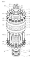
- FIG. 4 is an exploded perspective view of a pinch gear.
- FIG. 5 illustrates an internal structure of the power transmission pin of FIG. 4 .
- a transmission device for converting a torque which includes a rack having a plurality of rack tooth profiles, a plurality of pin gears provided separated from each other in a lengthwise direction of the rack, each pin gear having a plurality of power transmission pins relatively rotating along the plurality of rack tooth profiles for power transmission, and an input gear arranged between the pin gears and connecting the plurality of pin gears to be capable of rotating to allow the plurality of pin gears to rotate at the same speed.
- Each of the plurality of pin gears includes a body for rotatably supporting the plurality of power transmission pins, and a rotation support bearing unit coupled to a center area of the body and supporting a rotational motion of the body.
- the body may be provided by a pair of bodies that are arranged separated from each other and parallel to each other to be are connected to opposite end portions of each of the plurality of power transmission pins.
- the rotation support bearing unit may be arranged at each of the pair of bodies to be symmetrically so that a radial load generated in the power transmission with the input gear is offset and an external force added to the rotation support bearing unit is reduced.
- the rotation support bearing unit may include a plurality of pin support bearings arranged at an equiangular interval along a circumferential direction of the body as many as the number of the plurality of power transmission pins and supporting rotational motions of the plurality of power transmission pins, and a center portion rotation shaft provided at a rotation center portion of the body and forming a center of rotation with respect to the body and a center of revolution with respect to the plurality of power transmission pins.
- the center portion rotation shaft may be coupled to the body by a plurality of coupling members.
- the rotation support bearing unit may further include a center portion rotation shaft support bearing that is coaxially arranged with the center portion rotation shaft between the center portion rotation shaft and the body and supporting the center of rotation according to a rotational motion of the body.
- the rotation support bearing unit may further include a center portion oil seal that is connected to the center portion rotation shaft support bearing and lubricating and hermetically sealing the center portion rotation shaft support bearing.
- the rotation support bearing unit may further include a plurality of outer oil seals that are provided corresponding to the plurality of pin support bearings one by one and seals a plurality of pin insertion support holes in which the plurality of power transmission pins are inserted and supported are formed in the body.
- a lubricant flow hole through which a lubricant flows may be provided in each of the plurality of power transmission pins along a lengthwise direction of each of the plurality of power transmission pins.
- a lubricant inlet and a lubricant outlet, through which the lubricant is input and output, may be provided in a lateral wall of each of the power transmission pins to be connected to the lubricant flow hole.
- the lubricant input and the lubricant output may be arranged in opposite directions along a radial direction of the plurality of power transmission pins at opposite end portions of the lubricant flow hole.
- the input gear may include an input gear main body where a plurality of input tooth profiles are formed on an outer surface along a circumferential direction thereof to correspond to the plurality of power transmission pins of the plurality of pin gears and interact with the plurality of power transmission pins, and an input gear shaft protruding from a center area of the input gear main body.
- the plurality of input tooth profiles may be any one of tooth profiles selected from a trochoid tooth profile, a cycloid tooth profile, and an involute tooth profile.
- the input gear may be a single input gear and the plurality of pin gears may be provided by a pair with respect to the single input gear arranged between the plurality of pin gears.
- FIG. 1 is a perspective view illustrating a use state of a transmission device for converting a torque according to an embodiment of the present invention.
- FIG. 2 is an enlarged perspective view of major portions in FIG. 1 .
- FIG. 3 is an enlarged perspective view of an input gear.
- FIG. 4 is an exploded perspective view of a pinch gear.
- FIG. 5 illustrates an internal structure of the power transmission pin of FIG. 4 .
- the transmission device for converting a torque includes a rack 110 having a plurality of rack tooth profiles 111 , a plurality of pin gears 120 provided separated from each other in a lengthwise direction of the rack 110 , each of the pin gears 120 having a plurality of power transmission pins 140 relatively rotating along the rack tooth profiles 111 for power transmission, and an input gear 180 arranged between the pin gears 120 and connecting the pin gears 120 to be capable of rotating so that the pin gears 120 rotate at the same speed.
- the rack 110 is a linear rod gear and performs a linear motion in interaction with the pin gears 120 .
- an increased nominal load capacity may be provided compared to a conventional technology while using the rack 110 having a limited size. In other words, not only the number of parts decreases but also foot print of a device decreases as well and thus the capacity may be increased at least twice compared to the conventional technology.
- the rack tooth profiles 111 are continuously formed in the lengthwise direction of the rack 110 at one side of the rack 110 .
- the rack tooth profiles 111 may adopt any one of a trochoid tooth profile, a cycloid tooth profile, and an involute tooth profile.
- the pin gears 120 While the rack 110 performs a linear motion, the pin gears 120 perform a rotational motion. In the present embodiment, two pin gears 120 having the same structure are provided. Since this structure is a mere example, three or more pin gears 120 may be combined to be used.
- the transmission device for converting a torque may provide appropriate power to a processing apparatus (not shown) while the pin gears 120 move with respect to the rack 110 or the rack 110 moves with respect to the pin gears 120 .
- Each of the pin gears 120 includes a pair of bodies 130 , the power transmitting pins 140 rotatably supported by the bodies 130 and relatively rotating along the rack tooth profiles 111 of the rack 110 for power transmission, and a rotation support bearing unit 150 coupled to a center area of each of the bodies 130 and supporting a rotational motion of the bodies 130 .
- the bodies 130 are arranged in a pair separated from each other by the length of each of the power transmission pins 140 or less than the length thereof.
- the bodies 130 are connected to the opposite end portions of each of the power transmission pins 140 and rotatably support the power transmission pins 140 .
- a plurality of pin insertion support holes 131 in which the power transmission pins 140 are inserted and supported are provided in the bodies 130 at an equiangular interval along a circumferential direction.
- the power transmission pins 140 are rotatably supported between the bodies 130 and interact with the rack tooth profiles 111 of the rack 110 . In other words, as the power transmission pins 140 each are engaged with the rack tooth profiles 111 to interact with each other, desired power is transmitted.
- the power transmission pins 140 When the power transmission pins 140 are coupled to the bodies 130 , if the power transmission pins 140 are fixed to the bodies 130 by a press-in method, the power transmission pins 140 of the bodies 130 revolve around the bodies 130 . However, in the present embodiment, the power transmission pins 140 are coupled to the bodies 130 to be simultaneously capable of relatively rotating with respect to the bodies 130 at their positions. In other words, as described below, the power transmission pins 140 may perform rotational motions at their positions by means of a plurality of pin support bearings 152 .
- the power transmission pins 140 simultaneously rotate and revolve along the bodies 130 .
- the rotation of the power transmission pins 140 are made only when the power transmission pins 140 interact with the rack tooth profiles 111 of the rack 110 in contact with the rack tooth profiles 111 .
- a lubrication structure for maintaining the rotation of the power transmission pins 140 smooth on the bodies 130 is provided.
- a lubricant flow hole 141 through which a lubricant flows is provided in each of the power transmission pins 140 along the lengthwise direction of each of the power transmission pins 140 .
- a lubricant outlet 142 and a lubricant inlet 143 through which the lubricant is input and output through the lubricant flow hole 141 , are provided in a lateral wall of each of the power transmission pins 140 to be connected to the lubricant flow hole 141 .
- the lubricant outlet 142 and the lubricant inlet 143 may be arranged in the opposite directions along a radial direction of each of the power transmission pins 140 at the opposite end portions of the lubricant flow hole 141 , as illustrated in FIG. 5 .
- the present invention is not limited thereto and the lubricant outlet 142 and the lubricant inlet 143 may be arranged in the same direction.
- the rotation support bearing unit 150 is coupled to a center area of each of the bodies 130 to support the rotational motions of the bodies 130 .
- the rotation support bearing unit 150 is symmetrically coupled to the bodies 130 . Accordingly, a radial load generated during the transmission of power with the input gear 180 may be offset and thus an external force added to the rotation support bearing unit 150 may be reduced. As a result, durability of the rotation support bearing unit 150 is improved so that a long term use thereof may be achieved.
- the rotation support bearing unit 150 may endure a load twice or more compared to a conventional technology based on the same bearing.
- the rotation support bearing unit 150 includes a plurality of pin support bearings 152 , a center portion rotation shaft 154 , and a center portion rotation shaft support bearing 156 .
- the pin support bearings 152 are arranged at an equiangular interval along a circumferential direction of the bodies 130 as many as the number of the power transmission pins 140 , to respectively support the rotational motions of the power transmission pins 140 .
- a variety of roll bearings exhibiting superior strength including ball bearings may be used as the pin support bearings 152 .
- An outer oil seal 159 is arranged between each of the pin support bearings 152 and each of the power transmission pins 140 to hermetically seal each of the pin insertion support holes 131 in which the power transmission pins 140 are inserted and supported.
- the center portion rotation shaft 154 is provided at the rotational center portion of each of the bodies 130 a and forms a rotational center with respect to each of the bodies 130 and a revolving center with respect to the power transmission pins 140 .
- the center portion rotation shaft 154 forms a rotational center of each of the pin gears 120 .
- the center portion rotation shaft 154 is coupled to the rotational center portion of each of the bodies 130 by a plurality of coupling members 161 .
- a plurality of coupling holes 154 a to which the coupling members 161 may be coupled are formed in the center portion rotation shaft 154 .
- the center portion rotation shaft support bearing 156 is coaxially arranged with the center portion rotation shaft 154 between the center portion rotation shaft 154 and each of the bodies 130 , to support the rotation center according to the rotational motions of the bodies 130 .
- a variety of roll bearings exhibiting superior strength including ball bearings may be used as the center portion rotation shaft support bearing 156 .
- a center portion oil seal 158 is provided around the center portion rotation shaft support bearing 156 .
- the center portion oil seal 158 is connected to the center portion rotation shaft support bearing 156 to lubricate and seal the center portion rotation shaft support bearing 156 .
- the input gear 180 is arranged between the pin gears 120 to rotatably connect the pin gears 120 so that the pin gears 120 , that is, two pin gears in the present embodiment, may be rotated at the same speed.
- the input gear 180 includes an input gear main body 181 where a plurality of input tooth profiles 182 are formed on an outer surface along a circumferential direction thereof to correspond to the power transmission pins 140 of the pin gears 120 and interact with the power transmission pins 140 , and an input gear shaft 183 protruding from a center area of the input gear main body 181 .
- the input gear main body 181 is provided to be smaller than the size of each of the pin gear 120 . Accordingly, the number of the input tooth profiles 182 formed on the outer surface of the input gear main body 181 is smaller than that of the power transmission pins 140 . As a result, the input gear main body 181 with the pin gears 120 is advantageous in obtaining a deceleration rate.
- the number of the input tooth profiles 182 may be appropriately designed according to an environment of a process where the power transmission device according to the present embodiment is used.
- the input tooth profiles 182 may be any one of tooth profiles selected from a trochoid tooth profile, a cycloid tooth profile, and an involute tooth profile.
- the input gear shaft 183 may be a portion to which a driving apparatus that is not illustrated.
- the driving apparatus When the driving apparatus is connected to the input gear shaft 183 , the initial power is provided through the input gear shaft 183 toward the input gear 180 and then transmitted to the rack 110 via the pin gears 120 .
- the pin gears 120 When the pin gears 120 are rotated, the power transmission pins 140 provided in each of the pin gears 120 are engaged with the rack tooth profiles 111 of the rack 110 one by one to interact with each other. In other words, the pin gears 120 perform rotational motions and the rack 110 performs a linear motion.
- the rack 110 when the pin gears 120 perform rotational motions at their positions, the rack 110 performs a linear motion and thus power according to the linear motion of the rack 110 may be provided to the processing apparatus. Reversely, when the rack 110 is in a fixed state, the pin gears 120 are moved along the rack 110 while rotating and thus the linear motion or the rotational motion may be provided to the processing apparatus.
- the power transmission device having the above structure and operation, since one or a plurality of pin gears are driven with a single driving apparatus, not only an increased nominal load capacity is provided compared to the conventional technology but also a desired level of a deceleration rate is obtained without a complex deceleration device while using the rack of a limited size.
- all rolling motions including a rotational motion by the input gear and a linear motion by the rack are available so that efficiency in power transmission may be improved.
- the power transmission device may be used for a variety of machine tools needing a rotational motion or a linear motion and further for industrial mechanical apparatuses, semiconductor or flat panel display manufacturing equipment, and various goods transport equipment.
Landscapes
- Engineering & Computer Science (AREA)
- General Engineering & Computer Science (AREA)
- Mechanical Engineering (AREA)
- Transmission Devices (AREA)
- Retarders (AREA)
- General Details Of Gearings (AREA)
- Gears, Cams (AREA)
Applications Claiming Priority (3)
| Application Number | Priority Date | Filing Date | Title |
|---|---|---|---|
| KR1020110035467A KR101101900B1 (ko) | 2011-04-18 | 2011-04-18 | 동력전달장치 |
| KR10-2011-0035467 | 2011-04-18 | ||
| PCT/KR2012/000660 WO2012144725A2 (ko) | 2011-04-18 | 2012-01-30 | 동력전달장치 |
Publications (2)
| Publication Number | Publication Date |
|---|---|
| US20140026692A1 US20140026692A1 (en) | 2014-01-30 |
| US9341247B2 true US9341247B2 (en) | 2016-05-17 |
Family
ID=45613640
Family Applications (1)
| Application Number | Title | Priority Date | Filing Date |
|---|---|---|---|
| US14/112,539 Active 2032-11-11 US9341247B2 (en) | 2011-04-18 | 2012-01-30 | Power transmission device |
Country Status (6)
| Country | Link |
|---|---|
| US (1) | US9341247B2 (de) |
| EP (1) | EP2700848B1 (de) |
| JP (1) | JP5726372B2 (de) |
| KR (1) | KR101101900B1 (de) |
| CN (1) | CN103502693B (de) |
| WO (1) | WO2012144725A2 (de) |
Cited By (4)
| Publication number | Priority date | Publication date | Assignee | Title |
|---|---|---|---|---|
| US20180274650A1 (en) * | 2017-03-22 | 2018-09-27 | Safran Landing Systems | Roller gearing element |
| US10513328B2 (en) * | 2014-03-17 | 2019-12-24 | Airbus Operations Limited | Roller gear for a drive system |
| US11499609B2 (en) * | 2018-04-30 | 2022-11-15 | Nexen Group, Inc. | Rotary to linear torque transmission device |
| US20220388636A1 (en) * | 2019-11-08 | 2022-12-08 | Safran Landing Systems | Roller gear element |
Families Citing this family (13)
| Publication number | Priority date | Publication date | Assignee | Title |
|---|---|---|---|---|
| CN103335089A (zh) * | 2013-07-01 | 2013-10-02 | 李斌 | 滚动摩擦齿轮 |
| DE102014100444B4 (de) * | 2014-01-16 | 2017-06-29 | MAQUET GmbH | Vorrichtung zum linearen Verschieben einer Patientenlagerfläche und Verfahren zur Montage einer derartigen Vorrichtung |
| CN103976870B (zh) * | 2014-06-09 | 2016-01-20 | 郑天郢 | 一种可携带排烟自动调整高度行走悬灸啄灸装置 |
| CN104373538A (zh) * | 2014-10-16 | 2015-02-25 | 武汉理工大学 | 一种复合摆线发生装置 |
| KR101561140B1 (ko) * | 2014-10-28 | 2015-10-20 | 에스엔유 프리시젼 주식회사 | 기판 회전 정렬장치 |
| KR101587833B1 (ko) * | 2015-01-20 | 2016-01-22 | 주식회사 세진아이지비 | 동력전달장치 |
| KR101652703B1 (ko) * | 2015-02-02 | 2016-09-01 | 주식회사 세진아이지비 | 동력전달장치 |
| US10153554B2 (en) * | 2016-08-31 | 2018-12-11 | Apple Inc. | Electronic device antennas with harmonic resonances |
| GB2562019A (en) * | 2016-11-14 | 2018-11-07 | Airbus Operations Ltd | Roller components |
| JP6139810B1 (ja) * | 2017-01-05 | 2017-05-31 | 加茂精工株式会社 | ピンローラ形ピニオン装置 |
| KR101904117B1 (ko) * | 2017-03-14 | 2018-10-04 | 주식회사 세진아이지비 | 가이드 모듈 및 그를 구비하는 구동장치 |
| JP6584045B1 (ja) | 2019-06-28 | 2019-10-02 | 加茂精工株式会社 | ピニオンおよび動力伝達装置 |
| EP4607061B1 (de) * | 2024-02-21 | 2025-12-31 | Jörg Beutler | Antriebssystem |
Citations (12)
| Publication number | Priority date | Publication date | Assignee | Title |
|---|---|---|---|---|
| US1140427A (en) * | 1913-10-04 | 1915-05-25 | George H Wilson | Roller gear-wheel. |
| JPS5786652A (en) | 1980-11-14 | 1982-05-29 | Seibu Denki Kogyo Kk | Motive power transmission mechanism |
| JPH05187502A (ja) | 1992-01-16 | 1993-07-27 | Teijin Seiki Co Ltd | 直進運動機構 |
| JPH10184842A (ja) | 1996-12-25 | 1998-07-14 | Kamo Seiko Kk | 回転運動と直線運動の変換装置 |
| CN1366590A (zh) | 2000-04-27 | 2002-08-28 | 世津株式会社 | 内啮合行星齿轮结构的传动装置 |
| JP2003090407A (ja) | 2001-09-19 | 2003-03-28 | Ryozo Ota | 2個のピニオンとラックとの同時噛合せ構造 |
| JP2009074582A (ja) | 2007-09-19 | 2009-04-09 | Oriental Motor Co Ltd | 直線駆動用アクチュエータ |
| CN101532561A (zh) | 2009-02-23 | 2009-09-16 | 舒敬平 | 直齿圆柱圆锥转动齿齿轮直齿转动齿齿条 |
| KR100945193B1 (ko) | 2009-06-10 | 2010-03-03 | 주식회사 세진아이지비 | 동력전달장치 |
| WO2010143813A2 (ko) | 2009-06-10 | 2010-12-16 | 주식회사 세진아이지비 | 동력전달장치 |
| US20130186213A1 (en) * | 2010-10-29 | 2013-07-25 | Sejin-iGB Co., Ltd. | Power transmission device |
| US8893568B2 (en) * | 2011-07-08 | 2014-11-25 | Kamoseiko Kabushiki Kaisha | Self-lubricating transmission device |
-
2011
- 2011-04-18 KR KR1020110035467A patent/KR101101900B1/ko active Active
-
2012
- 2012-01-30 WO PCT/KR2012/000660 patent/WO2012144725A2/ko not_active Ceased
- 2012-01-30 CN CN201280018864.5A patent/CN103502693B/zh active Active
- 2012-01-30 JP JP2014506315A patent/JP5726372B2/ja active Active
- 2012-01-30 US US14/112,539 patent/US9341247B2/en active Active
- 2012-01-30 EP EP12773789.8A patent/EP2700848B1/de active Active
Patent Citations (19)
| Publication number | Priority date | Publication date | Assignee | Title |
|---|---|---|---|---|
| US1140427A (en) * | 1913-10-04 | 1915-05-25 | George H Wilson | Roller gear-wheel. |
| JPS5786652A (en) | 1980-11-14 | 1982-05-29 | Seibu Denki Kogyo Kk | Motive power transmission mechanism |
| JPH05187502A (ja) | 1992-01-16 | 1993-07-27 | Teijin Seiki Co Ltd | 直進運動機構 |
| JPH10184842A (ja) | 1996-12-25 | 1998-07-14 | Kamo Seiko Kk | 回転運動と直線運動の変換装置 |
| US6023989A (en) | 1996-12-25 | 2000-02-15 | Kamoseiko Kabushiki Kaisha | Transmission device for converting a torque between rotary movement and linear movement |
| CN1366590A (zh) | 2000-04-27 | 2002-08-28 | 世津株式会社 | 内啮合行星齿轮结构的传动装置 |
| JP2003090407A (ja) | 2001-09-19 | 2003-03-28 | Ryozo Ota | 2個のピニオンとラックとの同時噛合せ構造 |
| JP2009074582A (ja) | 2007-09-19 | 2009-04-09 | Oriental Motor Co Ltd | 直線駆動用アクチュエータ |
| CN101532561A (zh) | 2009-02-23 | 2009-09-16 | 舒敬平 | 直齿圆柱圆锥转动齿齿轮直齿转动齿齿条 |
| KR100945193B1 (ko) | 2009-06-10 | 2010-03-03 | 주식회사 세진아이지비 | 동력전달장치 |
| WO2010143813A2 (ko) | 2009-06-10 | 2010-12-16 | 주식회사 세진아이지비 | 동력전달장치 |
| WO2010143814A2 (ko) | 2009-06-10 | 2010-12-16 | 주식회사 세진아이지비 | 동력전달장치 |
| US20120090415A1 (en) * | 2009-06-10 | 2012-04-19 | Sejin-Igb. Co., Ltd. | Power transmitting apparatus |
| JP2012529605A (ja) | 2009-06-10 | 2012-11-22 | セジン−アイジービー.カンパニー,リミテッド | 動力伝達装置 |
| US8671788B2 (en) * | 2009-06-10 | 2014-03-18 | Sejin-iGB Co., Ltd. | Power transmitting apparatus |
| EP2441979B1 (de) | 2009-06-10 | 2014-03-19 | SEJIN-IGB Co., Ltd. | Kraftübertragungsvorrichtung |
| US8893569B2 (en) * | 2009-06-10 | 2014-11-25 | Sejin-iGB Co., Ltd. | Power transmitting apparatus |
| US20130186213A1 (en) * | 2010-10-29 | 2013-07-25 | Sejin-iGB Co., Ltd. | Power transmission device |
| US8893568B2 (en) * | 2011-07-08 | 2014-11-25 | Kamoseiko Kabushiki Kaisha | Self-lubricating transmission device |
Cited By (7)
| Publication number | Priority date | Publication date | Assignee | Title |
|---|---|---|---|---|
| US10513328B2 (en) * | 2014-03-17 | 2019-12-24 | Airbus Operations Limited | Roller gear for a drive system |
| US11407501B2 (en) * | 2014-03-17 | 2022-08-09 | Airbus Operations Limited | Roller gear for a drive system |
| US20180274650A1 (en) * | 2017-03-22 | 2018-09-27 | Safran Landing Systems | Roller gearing element |
| US11549577B2 (en) * | 2017-03-22 | 2023-01-10 | Safran Landing Systems | Roller gearing element |
| US11499609B2 (en) * | 2018-04-30 | 2022-11-15 | Nexen Group, Inc. | Rotary to linear torque transmission device |
| US20220388636A1 (en) * | 2019-11-08 | 2022-12-08 | Safran Landing Systems | Roller gear element |
| US11834156B2 (en) * | 2019-11-08 | 2023-12-05 | Safran Landing Systems | Roller gear element |
Also Published As
| Publication number | Publication date |
|---|---|
| EP2700848B1 (de) | 2015-10-21 |
| EP2700848A2 (de) | 2014-02-26 |
| EP2700848A4 (de) | 2014-11-26 |
| CN103502693A (zh) | 2014-01-08 |
| CN103502693B (zh) | 2016-03-23 |
| WO2012144725A2 (ko) | 2012-10-26 |
| JP2014513253A (ja) | 2014-05-29 |
| WO2012144725A3 (ko) | 2013-01-17 |
| KR101101900B1 (ko) | 2012-01-02 |
| JP5726372B2 (ja) | 2015-05-27 |
| US20140026692A1 (en) | 2014-01-30 |
Similar Documents
| Publication | Publication Date | Title |
|---|---|---|
| US20140026692A1 (en) | Power transmission device | |
| CN102549305B (zh) | 动力传递装置 | |
| US10865853B2 (en) | Multi-crankshaft cycloidal pin wheel reducer | |
| TWI273009B (en) | Speed reducer for industrial robot | |
| CA2976288C (en) | Transmission method and device for coaxially outputting rotation and revolution | |
| CN103968007A (zh) | 减速器 | |
| CN101166607B (zh) | 工业机器人的摆动部分的结构 | |
| JP2013142416A (ja) | 偏心揺動型の減速機のシリーズ | |
| CN107208746B (zh) | 动力传输器件 | |
| CN103742609A (zh) | 一种行星减速器 | |
| EP3364071A2 (de) | Innenverzahnter übertragungsmechanismus | |
| EP3550177A1 (de) | Planetenuntersetzungsgetriebe mit kleiner zahndifferenz, fahrzeuginterne anzeige und fahrzeug | |
| CN105473891A (zh) | 减速机 | |
| CN103603329A (zh) | 提升齿轮箱和自升式海洋平台 | |
| CN207034097U (zh) | 一种微小型高刚性减速机 | |
| CN107477151A (zh) | 内啮合传动机构 | |
| CN106536974A (zh) | 无轨道齿轮箱 | |
| CN103307214A (zh) | 一种少齿差共面双内啮合齿轮及采用其的减速器 | |
| CN104832602A (zh) | 一种多曲轴摆线减速机的动力输出装置 | |
| US20090036244A1 (en) | Mechanical speed reducer by chain | |
| CN104154185A (zh) | 一种内置行星传动高刚度少齿差齿轮传动装置 | |
| CN109139812A (zh) | 一种新型摆线行星减速装置 | |
| CN104819253A (zh) | 一种多曲轴摆线减速机 | |
| CN106402351A (zh) | 行星齿轮减速机输入端缓冲安装结构 | |
| CN108044645A (zh) | 一种变厚机器人关节传动结构 |
Legal Events
| Date | Code | Title | Description |
|---|---|---|---|
| AS | Assignment |
Owner name: SEJIN-IGB CO., LTD., KOREA, REPUBLIC OF Free format text: ASSIGNMENT OF ASSIGNORS INTEREST;ASSIGNOR:LIM, SUN HO;REEL/FRAME:031429/0565 Effective date: 20131010 |
|
| STCF | Information on status: patent grant |
Free format text: PATENTED CASE |
|
| MAFP | Maintenance fee payment |
Free format text: PAYMENT OF MAINTENANCE FEE, 4TH YR, SMALL ENTITY (ORIGINAL EVENT CODE: M2551); ENTITY STATUS OF PATENT OWNER: SMALL ENTITY Year of fee payment: 4 |
|
| MAFP | Maintenance fee payment |
Free format text: PAYMENT OF MAINTENANCE FEE, 8TH YR, SMALL ENTITY (ORIGINAL EVENT CODE: M2552); ENTITY STATUS OF PATENT OWNER: SMALL ENTITY Year of fee payment: 8 |