US9386565B2 - Method for transmitting control information and device for same - Google Patents
Method for transmitting control information and device for same Download PDFInfo
- Publication number
- US9386565B2 US9386565B2 US14/000,859 US201214000859A US9386565B2 US 9386565 B2 US9386565 B2 US 9386565B2 US 201214000859 A US201214000859 A US 201214000859A US 9386565 B2 US9386565 B2 US 9386565B2
- Authority
- US
- United States
- Prior art keywords
- pucch
- subframe
- downlink
- ack
- dai
- Prior art date
- Legal status (The legal status is an assumption and is not a legal conclusion. Google has not performed a legal analysis and makes no representation as to the accuracy of the status listed.)
- Active, expires
Links
Images


Classifications
-
- H04W72/0406—
-
- H—ELECTRICITY
- H04—ELECTRIC COMMUNICATION TECHNIQUE
- H04W—WIRELESS COMMUNICATION NETWORKS
- H04W72/00—Local resource management
- H04W72/20—Control channels or signalling for resource management
- H04W72/21—Control channels or signalling for resource management in the uplink direction of a wireless link, i.e. towards the network
-
- H—ELECTRICITY
- H04—ELECTRIC COMMUNICATION TECHNIQUE
- H04L—TRANSMISSION OF DIGITAL INFORMATION, e.g. TELEGRAPHIC COMMUNICATION
- H04L1/00—Arrangements for detecting or preventing errors in the information received
- H04L1/12—Arrangements for detecting or preventing errors in the information received by using return channel
- H04L1/16—Arrangements for detecting or preventing errors in the information received by using return channel in which the return channel carries supervisory signals, e.g. repetition request signals
- H04L1/18—Automatic repetition systems, e.g. Van Duuren systems
- H04L1/1822—Automatic repetition systems, e.g. Van Duuren systems involving configuration of automatic repeat request [ARQ] with parallel processes
-
- H—ELECTRICITY
- H04—ELECTRIC COMMUNICATION TECHNIQUE
- H04L—TRANSMISSION OF DIGITAL INFORMATION, e.g. TELEGRAPHIC COMMUNICATION
- H04L1/00—Arrangements for detecting or preventing errors in the information received
- H04L1/12—Arrangements for detecting or preventing errors in the information received by using return channel
- H04L1/16—Arrangements for detecting or preventing errors in the information received by using return channel in which the return channel carries supervisory signals, e.g. repetition request signals
- H04L1/18—Automatic repetition systems, e.g. Van Duuren systems
- H04L1/1829—Arrangements specially adapted for the receiver end
- H04L1/1861—Physical mapping arrangements
-
- H—ELECTRICITY
- H04—ELECTRIC COMMUNICATION TECHNIQUE
- H04L—TRANSMISSION OF DIGITAL INFORMATION, e.g. TELEGRAPHIC COMMUNICATION
- H04L5/00—Arrangements affording multiple use of the transmission path
- H04L5/003—Arrangements for allocating sub-channels of the transmission path
- H04L5/0053—Allocation of signalling, i.e. of overhead other than pilot signals
- H04L5/0055—Physical resource allocation for ACK/NACK
-
- H—ELECTRICITY
- H04—ELECTRIC COMMUNICATION TECHNIQUE
- H04W—WIRELESS COMMUNICATION NETWORKS
- H04W52/00—Power management, e.g. Transmission Power Control [TPC] or power classes
- H04W52/04—Transmission power control [TPC]
- H04W52/06—TPC algorithms
- H04W52/14—Separate analysis of uplink or downlink
- H04W52/146—Uplink power control
-
- H—ELECTRICITY
- H04—ELECTRIC COMMUNICATION TECHNIQUE
- H04W—WIRELESS COMMUNICATION NETWORKS
- H04W52/00—Power management, e.g. Transmission Power Control [TPC] or power classes
- H04W52/04—Transmission power control [TPC]
- H04W52/06—TPC algorithms
- H04W52/16—Deriving transmission power values from another channel
-
- H—ELECTRICITY
- H04—ELECTRIC COMMUNICATION TECHNIQUE
- H04W—WIRELESS COMMUNICATION NETWORKS
- H04W52/00—Power management, e.g. Transmission Power Control [TPC] or power classes
- H04W52/04—Transmission power control [TPC]
- H04W52/30—Transmission power control [TPC] using constraints in the total amount of available transmission power
- H04W52/32—TPC of broadcast or control channels
- H04W52/325—Power control of control or pilot channels
-
- H—ELECTRICITY
- H04—ELECTRIC COMMUNICATION TECHNIQUE
- H04W—WIRELESS COMMUNICATION NETWORKS
- H04W52/00—Power management, e.g. Transmission Power Control [TPC] or power classes
- H04W52/04—Transmission power control [TPC]
- H04W52/38—TPC being performed in particular situations
-
- H—ELECTRICITY
- H04—ELECTRIC COMMUNICATION TECHNIQUE
- H04W—WIRELESS COMMUNICATION NETWORKS
- H04W72/00—Local resource management
- H04W72/20—Control channels or signalling for resource management
-
- H—ELECTRICITY
- H04—ELECTRIC COMMUNICATION TECHNIQUE
- H04L—TRANSMISSION OF DIGITAL INFORMATION, e.g. TELEGRAPHIC COMMUNICATION
- H04L1/00—Arrangements for detecting or preventing errors in the information received
- H04L1/12—Arrangements for detecting or preventing errors in the information received by using return channel
- H04L1/16—Arrangements for detecting or preventing errors in the information received by using return channel in which the return channel carries supervisory signals, e.g. repetition request signals
- H04L1/18—Automatic repetition systems, e.g. Van Duuren systems
- H04L1/1812—Hybrid protocols; Hybrid automatic repeat request [HARQ]
-
- H—ELECTRICITY
- H04—ELECTRIC COMMUNICATION TECHNIQUE
- H04L—TRANSMISSION OF DIGITAL INFORMATION, e.g. TELEGRAPHIC COMMUNICATION
- H04L5/00—Arrangements affording multiple use of the transmission path
- H04L5/003—Arrangements for allocating sub-channels of the transmission path
- H04L5/0053—Allocation of signalling, i.e. of overhead other than pilot signals
-
- H—ELECTRICITY
- H04—ELECTRIC COMMUNICATION TECHNIQUE
- H04W—WIRELESS COMMUNICATION NETWORKS
- H04W52/00—Power management, e.g. Transmission Power Control [TPC] or power classes
- H04W52/04—Transmission power control [TPC]
- H04W52/18—TPC being performed according to specific parameters
- H04W52/24—TPC being performed according to specific parameters using SIR [Signal to Interference Ratio] or other wireless path parameters
- H04W52/242—TPC being performed according to specific parameters using SIR [Signal to Interference Ratio] or other wireless path parameters taking into account path loss
-
- H—ELECTRICITY
- H04—ELECTRIC COMMUNICATION TECHNIQUE
- H04W—WIRELESS COMMUNICATION NETWORKS
- H04W52/00—Power management, e.g. Transmission Power Control [TPC] or power classes
- H04W52/04—Transmission power control [TPC]
- H04W52/38—TPC being performed in particular situations
- H04W52/40—TPC being performed in particular situations during macro-diversity or soft handoff
-
- H—ELECTRICITY
- H04—ELECTRIC COMMUNICATION TECHNIQUE
- H04W—WIRELESS COMMUNICATION NETWORKS
- H04W74/00—Wireless channel access
- H04W74/08—Non-scheduled access, e.g. ALOHA
- H04W74/0833—Random access procedures, e.g. with 4-step access
Definitions
- the present invention relates to a wireless communication system, and more specifically, to a method for transmitting control information and a device for the same.
- a wireless communication system is a multiple access system that supports communication among multiple users by sharing available system resources (e.g. bandwidth, transmit power, etc.) among the multiple users.
- the multiple access system may adopt a multiple access scheme such as Code Division Multiple Access (CDMA), Frequency Division Multiple Access (FDMA), Time Division Multiple Access (TDMA), Orthogonal Frequency Division Multiple Access (OFDMA), or Single Carrier Frequency Division Multiple Access (SC-FDMA).
- CDMA Code Division Multiple Access
- FDMA Frequency Division Multiple Access
- TDMA Time Division Multiple Access
- OFDMA Orthogonal Frequency Division Multiple Access
- SC-FDMA Single Carrier Frequency Division Multiple Access
- An object of the present invention devised to solve the problem lies in a method for efficiently transmitting control information in a wireless communication system and a device for the same.
- Another object of the present invention is to provide a method for efficiently transmitting uplink control information in a TDD (Time Division Duplex) system and efficiently managing resources for the same and a device for the same.
- TDD Time Division Duplex
- a method for transmitting uplink control information in a TDD (Time Division Duplex) wireless communication system comprising: transmitting HARQ-ACK (Hybrid Automatic Repeat reQuest-Acknowledgement) via a PUCCH (Physical Uplink Control Channel) in a subframe n, wherein a transmission power of the PUCCH is determined by using the following equation:
- a communication device configured to transmit uplink control information in a TDD wireless communication system
- the communication device comprising a radio frequency (RF) unit and a processor
- the processor is configured to transmit HARQ-ACK (Hybrid Automatic Repeat reQuest-Acknowledgement) via a PUCCH (Physical Uplink Control Channel) in a subframe n, and wherein a transmission power of the PUCCH is determined by the following equation:
- the transmission power for the PUCCH may be determined by using the following equation:
- h ⁇ ( ⁇ ) n HARQ + n SR - 1 N , wherein N is a positive integer, and n SR is used to adjust the transmission power for the PUCCH in relation to SR and is set to 0 or 1.
- the transmission power for the PUCCH may be determined by using the following equation:
- P PUCCH ⁇ ( n ) min ⁇ ⁇ P CMAX , c ⁇ ( n ) , P 0 ⁇ _ ⁇ PUCCH + PL c + h ⁇ ( ⁇ ) + ⁇ F ⁇ _ ⁇ PUCCH ⁇ ( F ) + ⁇ TxD ⁇ ( F ′ ) + g ⁇ ( i ) ⁇
- P PUCCH (n) represents the transmission power for the PUCCH
- P CMAX,c (n) represents a configured transmission power in the subframe n for the serving cell c
- P 0 _ PUCCH is a parameter set by a higher layer
- PL c is a downlink path loss estimate of the serving cell c
- ⁇ F _ PUCCH (F) represents a value corresponding to a PUCCH format
- ⁇ TxD (F′) is a value set by a higher layer or
- g(i) represents a current PUCCH
- the wireless communication system may operate in one of UL-DL configurations #1 to #6.
- the wireless communication system may operate in UL-DL configuration #5.
- control information can be efficiently transmitted in a wireless communication system.
- uplink control information can be efficiently transmitted in a TDD system and resources for the same can be efficiently managed.
- FIG. 1 illustrates physical channels used in a 3GPP LTE system and a signal transmission method using the same
- FIG. 2 illustrates a radio frame structure
- FIG. 3 illustrates a resource grid of a downlink slot
- FIG. 4 illustrates a downlink subframe structure
- FIG. 5 illustrates an uplink subframe structure
- FIG. 6 illustrates a procedure for transmitting TDD UL ACK/NACK (Uplink Acknowledgement/Negative Acknowledgement) in a single cell situation
- FIG. 7 illustrates a carrier aggregation (CA) communication system
- FIG. 8 illustrates cross-carrier scheduling
- FIGS. 9 and 10 illustrate an enhanced PUCCH format (E-PUCCH format) (i.e. PUCCH format 3);
- FIGS. 11 and 12 illustrate conventional PUCCH format 3 power control
- FIG. 13 illustrates a problem in the conventional PUCCH format 3 power control
- FIGS. 14 and 15 illustrate PUCCH format 3 power control according to an embodiment of the present invention.
- FIG. 16 illustrates a base station (BS) and a user equipment (UE) applicable to an embodiment of the present invention.
- Embodiments of the present invention are applicable to a variety of wireless access technologies such as Code Division Multiple Access (CDMA), Frequency Division Multiple Access (FDMA), Time Division Multiple Access (TDMA), Orthogonal Frequency Division Multiple Access (OFDMA), and Single Carrier Frequency Division Multiple Access (SC-FDMA).
- CDMA can be implemented as a radio technology such as Universal Terrestrial Radio Access (UTRA) or CDMA2000.
- TDMA can be implemented as a radio technology such as Global System for Mobile communications (GSM)/General Packet Radio Service (GPRS)/Enhanced Data Rates for GSM Evolution (EDGE).
- GSM Global System for Mobile communications
- GPRS General Packet Radio Service
- EDGE Enhanced Data Rates for GSM Evolution
- OFDMA can be implemented as a radio technology such as Institute of Electrical and Electronics Engineers (IEEE) 802.11 (Wireless Fidelity (Wi-Fi)), IEEE 802.16 (Worldwide interoperability for Microwave Access (WiMAX)), IEEE 802.20, Evolved UTRA (E-UTRA).
- UTRA is a part of Universal Mobile Telecommunications System (UMTS).
- 3GPP 3 rd Generation Partnership Project
- LTE Long Term Evolution
- E-UMTS Evolved UMTS
- LTE-UMTS Evolved UMTS
- LTE-UMTS Evolved UMTS
- LTE-A LTE-Advanced
- LTE-A is an evolution of 3GPP LTE.
- a UE receives information from a BS through downlink (DL) and transmits information to the BS through uplink (UL).
- Information transmitted/received between the UE and BS includes data and various types of control information, and various physical channels are present according to type/purpose of information transmitted/received between the UE and BS.
- FIG. 1 illustrates physical channels used in a 3GPP LTE system and a signal transmission method using the same.
- the UE When powered on or when a UE initially enters a cell, the UE performs initial cell search involving synchronization with a BS in step S 101 .
- the UE For initial cell search, the UE is synchronized with the BS and acquire information such as a cell Identifier (ID) by receiving a Primary Synchronization Channel (P-SCH) and a Secondary Synchronization Channel (S-SCH) from the BS. Then the UE may receive broadcast information from the cell on a Physical Broadcast Channel (PBCH).
- P-SCH Primary Synchronization Channel
- S-SCH Secondary Synchronization Channel
- PBCH Physical Broadcast Channel
- the UE may determine a downlink channel status by receiving a Downlink Reference Signal (DL RS) during initial cell search.
- DL RS Downlink Reference Signal
- the UE may acquire more specific system information by receiving a Physical Downlink Control Channel (PDCCH) and receiving a Physical Downlink Shared Channel (PDSCH) based on information of the PDCCH in step S 102 .
- PDCCH Physical Downlink Control Channel
- PDSCH Physical Downlink Shared Channel
- the UE may perform a random access procedure to access the BS in steps S 103 to S 106 .
- the UE may transmit a preamble to the BS on a Physical Random Access Channel (PRACH) (S 103 ) and receive a response message for preamble on a PDCCH and a PDSCH corresponding to the PDCCH (S 104 ).
- PRACH Physical Random Access Channel
- the UE may perform a contention resolution procedure by further transmitting the PRACH (S 105 ) and receiving a PDCCH and a PDSCH corresponding to the PDCCH (S 106 ).
- the UE may receive a PDCCH/PDSCH (S 107 ) and transmit a Physical Uplink Shared Channel (PUSCH)/Physical Uplink Control Channel (PUCCH) (S 108 ), as a general downlink/uplink signal transmission procedure.
- control information transmitted from the UE to the BS is called uplink control information (UCI).
- the UCI may include a Hybrid Automatic Repeat and request Acknowledgement/Negative-ACK (HARQ ACK/NACK) signal, scheduling request (SR), a Channel Quality Indicator (CQI), a Precoding Matrix Index (PMI), a Rank Indicator (RI), etc.
- HARQ ACK/NACK Hybrid Automatic Repeat and request Acknowledgement/Negative-ACK
- SR scheduling request
- CQI Channel Quality Indicator
- PMI Precoding Matrix Index
- RI Rank Indicator
- HARQ ACK/NACK is simply referred to as HARQ-ACK or ACK/NACK(A/N).
- HARQ-ACK includes at least one of positive ACK (simply, ACK), negative ACK (NACK), DTX and NACK/DTX.
- the UCI is transmitted through a PUCCH in general, it may be transmitted via a PUSCH when control information and traffic data need to be simultaneously transmitted.
- the UCI may be aperiodically transmitted via a PUSCH at the request/instruction of a network.
- FIG. 2 illustrates a radio frame structure.
- uplink/downlink data packet transmission is performed on a subframe-by-subframe basis.
- a subframe is defined as a predetermined time interval including a plurality of OFDM symbols.
- 3GPP LTE supports a type-1 radio frame structure applicable to FDD (Frequency Division Duplex) and a type-2 radio frame structure applicable to TDD (Time Division Duplex).
- FIG. 2( a ) illustrates a type-1 radio frame structure.
- a downlink subframe includes 10 subframes each of which includes 2 slots in the time domain.
- a time for transmitting a subframe is defined as a transmission time interval (TTI).
- TTI transmission time interval
- each subframe has a length of 1 ms and each slot has a length of 0.5 ms.
- a slot includes a plurality of OFDM symbols in the time domain and includes a plurality of resource blocks (RBs) in the frequency domain. Since downlink uses OFDM in 3GPP LTE, an OFDM symbol represents a symbol period. The OFDM symbol may be called an SC-FDMA symbol or symbol period.
- An RB as a resource allocation unit may include a plurality of consecutive subcarriers in one slot.
- the number of OFDM symbols included in one slot may depend on Cyclic Prefix (CP) configuration.
- CPs include an extended CP and a normal CP.
- the number of OFDM symbols included in one slot may be 7.
- the length of one OFDM symbol increases, and thus the number of OFDM symbols included in one slot is smaller than that in case of the normal CP.
- the number of OFDM symbols allocated to one slot may be 6.
- the extended CP can be used to reduce inter-symbol interference.
- one subframe When the normal CP is used, one subframe includes 14 OFDM symbols since one slot has 7 OFDM symbols. The first three OFDM symbols at most in each subframe can be allocated to a PDCCH and the remaining OFDM symbols can be allocated to a PDSCH.
- FIG. 2( b ) illustrates a type-2 radio frame structure.
- the type-2 radio frame includes 2 half frames. Each half frame includes 5 subframes, a Downlink Pilot Time Slot (DwPTS), a Guard Period (GP), and an Uplink Pilot Time Slot (UpPTS), and one subframe consists of 2 slots.
- the DwPTS is used for initial cell search, synchronization or channel estimation.
- the UpPTS is used for channel estimation in a BS and UL transmission synchronization acquisition in a UE.
- the GP eliminates UL interference caused by multi-path delay of a DL signal between a UL and a DL.
- Table 1 shows UL-DL configurations of subframes in a radio frame in the TDD mode.
- D denotes a downlink subframe
- U denotes an uplink subframe
- S denotes a special subframe.
- the special subframe includes DwPTS (Downlink Pilot TimeSlot), GP (Guard Period), and UpPTS (Uplink Pilot TimeSlot).
- DwPTS is a period reserved for downlink transmission
- UpPTS is a period reserved for uplink transmission.
- the radio frame structure is merely exemplary and the number of subframes included in the radio frame, the number of slots included in a subframe, and the number of symbols included in a slot can be vary.
- FIG. 3 illustrates a resource grid of a downlink slot.
- a downlink slot includes a plurality of OFDM symbols in the time domain.
- One downlink slot may include 7(6) OFDM symbols, and one resource block (RB) may include 12 subcarriers in the frequency domain.
- Each element on the resource grid is referred to as a resource element (RE).
- One RB includes 12 ⁇ 7(6) REs.
- the number N RB of RBs included in the downlink slot depends on a downlink transmit bandwidth.
- the structure of an uplink slot may be same as that of the downlink slot except that OFDM symbols by replaced by SC-FDMA symbols.
- FIG. 4 illustrates a downlink subframe structure
- a maximum of three (four) OFDM symbols located in a front portion of a first slot within a subframe correspond to a control region to which a control channel is allocated.
- the remaining OFDM symbols correspond to a data region to which a physical downlink shared chancel (PDSCH) is allocated.
- Examples of downlink control channels used in LTE include a physical control format indicator channel (PCFICH), a physical downlink control channel (PDCCH), a physical hybrid ARQ indicator channel (PHICH), etc.
- the PCFICH is transmitted at a first OFDM symbol of a subframe and carries information regarding the number of OFDM symbols used for transmission of control channels within the subframe.
- the PHICH is a response of uplink transmission and carries an HARQ acknowledgment (ACK)/not-acknowledgment (NACK) signal.
- ACK HARQ acknowledgment
- NACK not-acknowledgment
- DCI downlink control information
- Formats 0, 3, 3A and 4 for uplink and formats 1, 1A, 1B, 1C, 1D, 2, 2A, 2B and 2C for downlink are defined as DCI formats.
- the DCI formats selectively include information such as hopping flag, RB allocation, MCS (Modulation Coding Scheme), RV (Redundancy Version), NDI (New Data Indicator), TPC (Transmit Power Control), cyclic shift DM RS (Demodulation Reference Signal), CQI (Channel Quality Information) request, HARQ process number, TPMI (Transmitted Precoding Matrix Indicator), PMI (Precoding Matrix Indicator) confirmation according as necessary.
- MCS Modulation Coding Scheme
- RV Redundancy Version
- NDI New Data Indicator
- TPC Transmit Power Control
- CQI Channel Quality Information
- HARQ process number HARQ process number
- TPMI Transmitted Precoding Matrix Indicator
- PMI Precoding Matrix Indicator
- a PDCCH may carry a transport format and a resource allocation of a downlink shared channel (DL-SCH), resource allocation information of an uplink shared channel (UL-SCH), paging information on a paging channel (PCH), system information on the DL-SCH, information on resource allocation of an upper-layer control message such as a random access response transmitted on the PDSCH, a set of Tx power control commands on individual UEs within an arbitrary UE group, a Tx power control command, information on activation of a voice over IP (VoIP), etc.
- a plurality of PDCCHs can be transmitted within a control region. The UE can monitor the plurality of PDCCHs.
- the PDCCH is transmitted on an aggregation of one or several consecutive control channel elements (CCEs).
- the CCE is a logical allocation unit used to provide the PDCCH with a coding rate based on a state of a radio channel.
- the CCE corresponds to a plurality of resource element groups (REGs).
- a format of the PDCCH and the number of bits of the available PDCCH are determined by the number of CCEs.
- the BS determines a PDCCH format according to DCI to be transmitted to the UE, and attaches a cyclic redundancy check (CRC) to control information.
- CRC cyclic redundancy check
- the CRC is masked with a unique identifier (referred to as a radio network temporary identifier (RNTI)) according to an owner or usage of the PDCCH.
- RNTI radio network temporary identifier
- a unique identifier e.g., cell-RNTI (C-RNTI)
- C-RNTI cell-RNTI
- P-RNTI paging-RNTI
- a system information RNTI (SI-RNTI) may be masked to the CRC.
- SI-RNTI system information RNTI
- RA-RNTI random access-RNTI
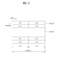
- FIG. 5 illustrates an uplink subframe structure
- an uplink subframe includes a plurality of (e.g. 2) slots.
- a slot may include different numbers of SC-FDMA symbols according to CP lengths.
- the uplink subframe is divided into a control region and a data region in the frequency domain.
- the data region is allocated with a PUSCH and used to carry a data signal such as audio data.
- the control region is allocated a PUCCH and used to carry uplink control information (UCI).
- the PUCCH includes an RB pair located at both ends of the data region in the frequency domain and hopped in a slot boundary.
- the PUCCH can be used to transmit the following control information.
- the quantity of control information (UCI) that a UE can transmit through a subframe depends on the number of SC-FDMA symbols available for control information transmission.
- the SC-FDMA symbols available for control information transmission correspond to SC-FDMA symbols other than SC-FDMA symbols of the subframe, which are used for reference signal transmission.
- SRS Sounding Reference Signal
- the last SC-FDMA symbol of the subframe is excluded from the SC-FDMA symbols available for control information transmission.
- a reference signal is used to detect coherence of the PUCCH.
- the PUCCH supports 7 formats according to information transmitted thereon.
- Table 2 shows the mapping relationship between PUCCH formats and UCI in LTE.
- UCI Uplink Control Information
- Format 1 SR (Scheduling Request) (non-modulated waveform) Format 1a 1-bit HARQ ACK/NACK (SR exist/non-exist) Format 1b 2-bit HARQ ACK/NACK (SR exist/non-exist) Format 2 CSI (20 coded bits) Format 2 CSI and 1- or 2-bit HARQ ACK/NACK (20 bits) (extended CP only) Format 2a CSI and 1-bit HARQ ACK/NACK (20 + 1 coded bits) Format 2b CSI and 2-bit HARQ ACK/NACK (20 + 2 coded bits) Format 3 HARQ ACK/NACK (+ SR) (48 bits) (LTE-A)
- UCI e.g. CQI/PMI, HARQ-ACK, RI, etc.
- the UE multiplexes UL-SCH data and the HARQ-ACK prior to DFT-spreading, and then transmits control information and data via a PUSCH.
- TDD divides a frequency band into DL subframes and UL subframes in the time domain to use the frequency band (refer to FIG. 2( b ) ). Accordingly, a larger number of DL subframes or a larger number of UL subframe may be allocated in a DL/UL asymmetrical data traffic situation, and thus DL subframes may not one-to-one correspond to UL subframes in TDD.
- the UE may need to transmit ACK/NACK responses to a plurality of PUSCHs (and/or PDCCHs which require ACK/NACK responses) on a plurality of DL subframes through one single UL subframe.
- the ratio of the number of DL subframes to the number of UL subframes can be set as M:1 according to TDD configuration.
- M denotes the number of DL subframes corresponding to one UL subframe.
- the UE needs to transmit ACK/NACK responses to a plurality of PDSCHs (or PDCCHs which require ACK/NACK responses) on M DL subframes through one UL subframe.
- FIG. 6 illustrates a procedure for transmitting TDD UL ACK/NACK.
- a UE can receive one or more PDSCH signals in M DL subframes (SFs) (S 502 _ 0 to S 502 _M ⁇ 1).
- SFs DL subframes
- Each PDSCH signal is used to transmit one or more (e.g. 2) transport blocks (TBs) (or codewords) according to transmission mode.
- a PDCCH signal requiring an ACK/NACK response for example, a PDCCH signal indicating (downlink) SPS (Semi-Persistent Scheduling) (simply, SPS release PDCCH signal) may also be received in step S 502 _ 0 to S 502 _M ⁇ 1, which is not shown.
- the UE transmits ACK/NACK through a UL subframe corresponding to the M DL subframes via processes for transmitting ACK/NACK (e.g. ACK/NACK (payload) generation, ACK/NACK resource allocation, etc.) (S 504 ).
- ACK/NACK includes acknowledgement information about the PDSCH signal and/or an SPS release PDCCH received in step S 502 _ 0 to S 502 _M ⁇ 1. While ACK/NACK is transmitted via a PUCCH basically, ACK/NACK is transmitted via a PUSCH when a PUSCH is transmitted at ACK/NACK transmission time.
- Various PUCCH formats shown in Table 2 can be used for ACK/NACK transmission.
- various methods such as ACK/NACK bundling and ACK/NACK channel selection can be used.
- ACK/NACK relating to data received in the M DL subframes is transmitted through one UL subframe (i.e. M DL SF(s): 1 UL SF) and the relationship therebetween is determined by a DASI (Downlink Association Set Index).
- DASI Downlink Association Set Index
- Table 3 shows DASI (K: ⁇ k0, k1, . . . , k ⁇ 1 ⁇ ) defined in LTE(-A).
- Table 3 shows spacing between a UL subframe transmitting ACK/NACK and a DL subframe relating to the UL subframe. Specifically, when a PDCCH that indicates PDSCH transmission and/or (downlink) SPS release is present in a subframe n ⁇ k (k ⁇ K), the UE transmits ACK/NACK in a subframe n.
- a TDD system includes a DAI (Downlink Assignment Index) in a PDCCH.
- the DAI represents an accumulation value (i.e. counted value) of PDCCH(s) corresponding to PDSCH(s) and PDCCHs) indicating (downlink) SPS release up to the current subframe within DL subframes(s) n ⁇ k (k ⁇ K).
- downlink scheduling-related PDCCHs e.g. a PDCCH corresponding to a PDSCH, and a downlink SPS release PDCCH
- a DAI included in the PDSCH-scheduling PDCCH and (downlink) SPS release PDCCH is referred to as a DL DAI, DAI-c (counter), or simply DAI.
- Table 4 shows a value V DAI DL indicated by a DL DAI field.
- FIG. 7 illustrates a carrier aggregation (CA) communication system.
- CA carrier aggregation
- an LTE-A system employs CA (or bandwidth aggregation) technology which aggregates a plurality of UL/DL frequency blocks to obtain a wider UL/DL bandwidth.
- Each frequency block is transmitted using a component carrier (CC).
- the CC can be regarded as a carrier frequency (or center carrier, center frequency) for the frequency block.
- a plurality of UL/DL CCs can be aggregated to support a wider UL/DL bandwidth.
- the CCs may be contiguous or non-contiguous in the frequency domain. Bandwidths of the CCs can be independently determined
- Asymmetrical CA in which the number of UL CCs is different from the number of DL CCs can be implemented. For example, when there are two DL CCs and one UL CC, the DL CCs can correspond to the UL CC in the ratio of 2:1.
- a DL CC/UL CC link can be fixed or semi-statically configured in the system.
- a frequency band that a specific UE can monitor/receive can be limited to M ( ⁇ N) CCs.
- Various parameters with respect to CA can be set cell-specifically, UE-group-specifically, or UE-specifically.
- Control information may be transmitted/received only through a specific CC.
- This specific CC can be referred to as a Primary CC (PCC) (or anchor CC) and other CCs can be referred to as Secondary CCs (SCCs).
- PCC Primary CC
- SCCs Secondary CCs
- a cell is defined as a combination of downlink resources and uplink resources. Yet, the uplink resources are not mandatory. Therefore, a cell may be composed of downlink resources only or both downlink resources and uplink resources.
- the linkage between the carrier frequencies (or DL CCs) of downlink resources and the carrier frequencies (or UL CCs) of uplink resources may be indicated by system information.
- a cell operating in primary frequency resources (or a PCC) may be referred to as a primary cell (PCell) and a cell operating in secondary frequency resources (or an SCC) may be referred to as a secondary cell (SCell).
- PCell primary cell
- SCell secondary cell
- the PCell is used for a UE to establish an initial connection or re-establish a connection.
- the PCell may refer to a cell operating on a DL CC SIB2-linked to a UL CC. Furthermore, the PCell may refer to a cell indicated during handover.
- the SCell may be configured after an RRC connection is established and may be used to provide additional radio resources.
- the PCell and the SCell may collectively be referred to as a serving cell. Accordingly, a single serving cell composed of a PCell only exists for a UE in an RRC_Connected state, for which CA is not set or which does not support CA.
- one or more serving cells exist, including a PCell and entire SCells, for a UE in an RRC_CONNECTED state, for which CA is set.
- a network may configure one or more SCells in addition to an initially configured PCell, for a UE supporting CA during connection setup after an initial security activation operation is initiated.
- a PDCCH for downlink allocation can be transmitted on DL CC #0 and a PDSCH corresponding thereto can be transmitted on DL CC #2.
- introduction of a carrier indicator field (CIF) can be considered. Presence or absence of the CIF in a PDCCH can be determined by higher layer signaling (e.g. RRC signaling) semi-statically and UE-specifically (or UE group-specifically).
- RRC signaling e.g. RRC signaling
- the BS can allocate a PDCCH monitoring DL CC to reduce BD complexity of the UE.
- the PDCCH monitoring DL CC set includes one or more DL CCs as parts of aggregated DL CCs and the UE detects/decodes a PDCCH only on the corresponding DL CCs. That is, when the BS schedules a PDSCH/PUSCH for the UE, a PDCCH is transmitted only via the PDCCH monitoring DL CC set.
- the PDCCH monitoring DL CC set can be set in a UE-specific, UE-group-specific or cell-specific manner.
- the term “PDCCH monitoring DL CC” can be replaced by the terms such as “monitoring carrier” and “monitoring cell”.
- the term “CC” aggregated for the UE can be replaced by the terms such as “serving CC”, “serving carrier” and “serving cell”.
- FIG. 8 illustrates scheduling when a plurality of carriers is aggregated. It is assumed that 3 DL CCs are aggregated and DL CC A is set to a PDCCH CC.
- DL CC A, DL CC B and DL CC C can be called serving CCs, serving carriers, serving cells, etc.
- CIF Carrier Indicator Field
- a DL CC can transmit only a PDCCH that schedules a PDSCH corresponding to the DL CC without a CIF (non-cross-CC scheduling).
- a specific CC e.g.
- DL CC A can transmit not only a PDCCH that schedules the PDSCH corresponding to the DL CC A but also PDCCHs that schedule PDSCHs of other DL CCs using the CIF (cross-CC scheduling).
- a PDCCH is not transmitted in DL CC B/C.
- LTE-A allows cross-carrier scheduling for a DL PCC and allows only self-carrier scheduling for a DL SCC.
- a PDCCH that schedules a PDSCH on the DL PCC can be transmitted only on the DL PCC.
- a PDCCH that schedules a PDSCH on the DL SCC can be transmitted on the DL PCC (cross-carrier scheduling) or transmitted on the DL SCC (self-carrier scheduling).
- E-PUCCH format i.e. PUCCH format 3
- PUCCH format 3 may be configured when a plurality of cells (or CCs) are configured for a corresponding UE.
- the E-PUCCH format i.e. PUCCH format 3
- the E-PUCCH format may be configured when one or more cells (or CCs) are configured for the corresponding UE.
- FIG. 9 illustrates a slot-level E-PUCCH format.
- a plurality of ACKs/NACK information are transmitted through joint coding (e.g. Reed-Muller coding, Tail-biting convolutional coding, etc.), block-spreading, and SC-FDMA modulation.
- joint coding e.g. Reed-Muller coding, Tail-biting convolutional coding, etc.
- block-spreading e.g. Reed-Muller coding, Tail-biting convolutional coding, etc.
- SC-FDMA modulation e.g. Reed-Muller coding, Tail-biting convolutional coding, etc.
- one symbol sequence is transmitted over a frequency domain and OCC (Orthogonal Cover Code) based time-domain spreading is applied to the symbol sequence.
- Control signals of multiple UEs can be multiplexed into the same RB using a OCC.
- 5 SC-FDMA symbols i.e. UCI data part
- the symbol sequence ⁇ d1, d2, . . . ⁇ may mean a modulated symbol sequence or a codeword bit sequence.
- ⁇ means the codeword bit sequence
- an RS symbol can be generated from a CAZAC (Constant Amplitude Zero Autocorrelation Sequence) having a specific cyclic shift.
- an RS can be transmitted by applying (multiplying) a specific OCC to a plurality of RS symbols in the time domain.
- FIG. 10 illustrates a subframe-level E-PUCCH format (i.e. PUCCH format 3).
- a symbol sequence ⁇ d′0 ⁇ d′11 ⁇ is mapped to a subcarrier in one SC-FDMA symbol and mapped to 5 SC-FDMA symbols according to block-spreading using an OCC (C1 to C5) in slot 0.
- a symbol sequence ⁇ d′12 ⁇ d′23 ⁇ is mapped to a subcarrier in one SC-FDMA symbol and mapped to 5 SC-FDMA symbols according to block-spreading using the OCC (C1 to C5) in slot 1.
- the symbol sequence ⁇ d′0 ⁇ d′11 ⁇ or ⁇ d′12 ⁇ d′23 ⁇ as shown in each slot is obtained by applying FFT or FFT/IFFT to the symbol sequence ⁇ d1, d2, .
- the symbol sequence ⁇ d′0 ⁇ d′11 ⁇ or ⁇ d′12 ⁇ d′23 ⁇ is a sequence obtained by applying FFT to the symbol sequence ⁇ d1, d2, . . . ⁇ of FIG. 9 , IFFT is additionally applied to ⁇ d′0 ⁇ d′11 ⁇ or ⁇ d′12 ⁇ d′23 ⁇ to generate SC-FDMA symbols.
- the entire symbol sequence ⁇ d′0 ⁇ d′23 ⁇ is generated by joint-coding one or more UCI, the first half ⁇ d′0 ⁇ d′11 ⁇ is transmitted through slot 0 and the second half ⁇ d′0 ⁇ d′11 ⁇ is transmitted through slot 1.
- the OCC may be changed on a slot basis and UCI data may be scrambled on an SC-FDMA symbol basis.
- E-PUCCH format 3 For details of the E-PUCCH format (i.e. PUCCH format 3), refer to 3GPP TS (Technical Specification) 36.211 V10.1.0 (2011. March), 36.212 V10.1.0 (2011. March) and 36.213 V10.1.0 (2011. March) published before the first priority date of the invention (2011. May 17).
- a description will be given of an ACK/NACK payload configuration method for PUCCH format 3 with reference to 36.213 V10.1.0 “7.3 UE procedure for reporting HARQ-ACK”.
- An ACK/NACK payload for PUCCH format 3 is configured for each CC and then configured ACK/NACK payloads are contiguous according to the order of cell index.
- HARQ-ACK feedback bits for a c-th serving cell are given as o c,0 ACK , o c,1 ACK , . . . , o c,O c ACK -1 ACK (c ⁇ 0).
- o c ACK represents the number of bits (i.e. size) of a HARQ-ACK payload for the c-th serving cell. This example corresponds to a case in which HARQ-ACK is modulated through BPSK (Binary Phase Shift Keying).
- M denotes the number of elements in a set K defined in Table 3.
- each HARQ-ACK bit in the HARQ-ACK payload of the serving cell corresponds to o c,DAI(k)-1 ACK .
- DAI(k) represents a DL DAI value of a PDCCH detected in DL subframe n ⁇ k.
- the position of each HARQ-ACK bit in the HARQ-ACK payload of the serving cell corresponds to o c,2DAI(k)-2 ACK and o c,2DAI(k)-1 ACK .
- the position of a HARQ-ACK bit for an SPS PDSCH corresponds to o c,O c ACK -1 ACK .
- o c,2DAI(k)-2 ACK represents HARQ-ACK for codeword 0
- o c,2DAI(k)-1 ACK represents HARQ-ACK for codeword 1.
- Codewords 0 and 1 respectively correspond to transport blocks 0 and 1 or transport blocks 1 and 0 according to swapping.
- a HARQ-ACK bit corresponding to no detected PDSCH or no detected SPS release PDCCH is set as NACK.
- FIG. 11 illustrates a procedure for transmitting HARQ-ACK using conventional PUCCH format 3.
- a BS transmits one or more PDCCHs and/or one or more PDSCHs to a UE (S 1102 ).
- the PDCCHs include (i) PDCCH with a corresponding PDSCH, and (ii) PDCCH without a corresponding PDSCH (e.g. SPS release PDCCH).
- the PDSCHs include (i) PDSCH with a corresponding PDCCH (i.e. PDSCH with PDCCH), and (ii) PDSCH without a corresponding PDCCH (i.e. PDSCH without PDCCH) (e.g. SPS PDSCH).
- the UE generates control information to be transmitted through PUCCH format 3.
- the control information includes HARQ-ACK information for the one or more PDCCHs and/or one or more PDSCHs, preferably, an SPS release PDCCH, PDSCH with PDCCH and PDSCH without PDSCH.
- the control information additionally includes an SR bit.
- the SR bit is added to the end (or the head) of a HARQ-ACK bitstream.
- a PUCCH format 3 signal is generated from the control information through the procedures illustrated in FIGS. 11 and 12 .
- the UE sets PUCCH transmission power for PUCCH transmission (S 1104 ), and the PUCCH format 3 signal is transmitted to the BS through a power control process (S 1106 ).
- P PUCCH ⁇ ( i ) min ⁇ ⁇ P CMAX , c ⁇ ( i ) , P 0 ⁇ _ ⁇ PUCCH + PL c + h ⁇ ( ⁇ ) + ⁇ F ⁇ _ ⁇ PUCCH ⁇ ( F ) + ⁇ TxD ⁇ ( F ′ ) + g ⁇ ( i ) ⁇ ⁇ [ dBm ]
- P CMAX,c (i) denotes a maximum value of transmission power set for the serving cell c, specifically, UE transmission power defined in the subframe i for the serving cell c, more specifically, maximum UE transmission power defined in the subframe i for the serving cell c.
- P O _ PUCCH is a parameter corresponding to the sum of P O _ NOMINAL _ PUCCH and P O _ UE _ PUCCH .
- P O _ NOMINAL _ PUCCH and P O _ UE _ PUCCH are provided by a higher layer (e.g. RRC (Radio Resource Control) layer).
- RRC Radio Resource Control
- PL c denotes a downlink path loss estimate for the serving cell c.
- PL c is calculated by the UE and obtained by using a difference between a reference signal power provided by a higher layer and a reference signal received power (RSRP).
- RSRP reference signal received power
- PL c may be given as referenceSignalPower—RSRP.
- ⁇ F _ PUCCH (F) is provided by a higher layer.
- Each value of ⁇ F _ PUCCH (F) represents a value corresponding to a PUCCH format with respect to PUCCH format 1a.
- PUCCH format F is as defined in Table 2.
- ⁇ F _ PUCCH (F) is 0, a negative integer or a positive integer.
- ⁇ F _ PUCCH (F) may be ⁇ 2 dB, 0 dB or 1 dB.
- parameter ⁇ TxD (F′) is provided by the higher layer.
- PUCCH format F′ is as defined in Table 2. Otherwise, that is, when the UE is configured to transmit a PUCCH through a single antenna port, ⁇ TxD (F′) is 0. That is, ⁇ TxD (F′) corresponds to a power compensation value in consideration of an antenna port transmission mode.
- h(•) is a PUCCH format dependent value.
- h(•) is a function having at least one of n CQI , n HARQ and n SR as a parameter.
- h(•) is a function of n HARQ and n SR in case of PUCCH format 3. Specifically,
- h ⁇ ( ⁇ ) n HARQ + n SR - 1 3 when the UE is configured to transmit a PUCCH signal through two antenna ports or the number of HARQ-ACK bits is greater than 11, and in other cases (i.e. single antenna port transmission)
- h ⁇ ( ⁇ ) n HARQ + n SR - 1 2 .
- n SR is 0 or 1, and is used to control PUCCH power in relation to SR.
- n HARQ is used to control PUCCH power in relation to HARQ-ACK.
- n HARQ is represented as Equation 2.
- N k,c received represents the number of PDCCHs and/or SPS PDSCHs (i.e. PDSCH without a corresponding PDCCH) received in subframe n ⁇ k (k ⁇ K) (refer to Table 3) and serving cell c. More generally, N k,c received denotes the number of PDCCHs that schedule the serving cell c, received in subframe n ⁇ k (k ⁇ K) (refer to Table 3), and/or SPS PDSCHs (i.e. PDSCH without a corresponding PDCCH) received in the serving cell c.
- N k,c received denotes the number of transport block(s) and/or (downlink) SPS release PDCCHs received in subframe n ⁇ k (k ⁇ K) (refer to Table 3) and serving cell c.
- N k,c received is an integer equal to or greater than 0.
- subframe n corresponds to subframe i in which a PUCCH signal is transmitted.
- n HARQ is represented as Equation 3.
- Equation 2 C, c and N k,c received are as defined in Equation 2.
- V DAI,c DL denotes a DL DAI value included in PDCCH lastly received by the UE from among PDCCHs that schedule the serving cell c.
- V DAI,c DL denotes a DL DAI value included in PDCCH lastly received by the UE from among PDCCHs for the serving cell c.
- Equivalently (refer to 36.213 V10.1.0 (2011. March) “7.3 UE procedure for reporting HARQ-ACK”), V DAI,c DL represents a DL DAI value included in a PDCCH detected by the UE in subframe n ⁇ k m and the serving cell c.
- k m is a minimum value of k corresponding to a detected PDCCH in set K (k ⁇ K) (refer to Table 3).
- the PDCCH includes a PDCCH for DL scheduling, for example, a PDCCH having DCI format 1/1A/1B/1D/2/2A/2B/2C.
- V DAI,c DL 0.
- U DAI,c denotes the number of PDCCHs that schedule the serving cell c, received by the UE.
- U DAI,c represents the number of PDCCHs for the serving cell c, received by the UE.
- Equivalently (refer to 36.213 V10.1.0 (2011. March) “7.3 UE procedure for reporting HARQ-ACK”)
- U DAI,c denotes the total number of PDCCHs detected by the UE in subframe n ⁇ k (k ⁇ K) (refer to Table 3) and the serving cell c.
- the PDCCHs include PDCCH with PDSCH and SPS release PDCCH.
- n c ACK denotes the number of HARQ-ACK bits corresponding to a configured DL transmission mode on the serving cell c.
- n c ACK 1.
- g(i) denotes a current PUCCH power control adjustment state.
- ⁇ PUCCH is a UE-specific correction value and may be called a TPC command.
- ⁇ PUCCH is included in a PDCCH having DCI format 1A/1B/1D/1/2A/2/2B/2C.
- ⁇ PUCCH is joint-coded with a different UE-specific PUCCH correction value on a PDCCH having DCI format 3/3A.
- FIG. 12 illustrates a HARQ-ACK payload configuration and PUCCH format 3 power control according thereto.
- DL SF indexes logically represent the order of M DL SFs. Actual DL SF indexes may be different from these DL SF indexes.
- FIG. 12 can correspond to both non-cross-CC scheduling and cross-CC scheduling.
- the BS transmits 3 PDCCHs in serving cell #3 to the UE.
- the number of HARQ-ACK bits for each serving cell is determined by a value of M according to a UL-DL configuration, a transmission mode, and whether spatial bundling is applied, and whether actual PDCCH and/or PDSCH transmission has been performed in the corresponding DL subframe is not considered.
- the conventional Equation 3 is used to determine n HARQ on the basis of the number of transport blocks (TBs) (or PDCCHs) scheduled for the UE for each serving cell and to perform final PUCCH power control by applying n HARQ .
- the number of PDCCHs that have not been detected by the UE (the UE can determine that the PDCCHs have not been detected although the UE has not received the PDCCHs) is multiplied by n c ACK (a maximum number of TBs that can be transmitted through serving cell c in a DL subframe when spatial bundling is not applied) and is summed with the number of TBs (or PDCCHs) actually received by the UE for each serving cell to calculate the number of TBs (or PDCCHs) scheduled for each serving cell, and the sum of the numbers of TBs for all serving cells is determined as final n HARQ .
- n c ACK a maximum number of TBs that can be transmitted through serving cell c in a DL subframe when spatial bundling is not applied
- V DAI,c DL ⁇ U DAI,c (V DAI,c DL ⁇ U DAI,c ) in Equation 3 is used to reflect DTX (i.e., PDCCH missed) detected by the UE in serving cell c into PUCCH power.
- FIG. 13 illustrates a problem in the above-described conventional power control method for PUCCH format 3.
- This example assumes that one cell is configured for a UE.
- the method illustrated in FIG. 12 may be applied to a case in which a plurality of cells are configured for the UE.
- This example is based on the assumption that a serving cell is configured to a transmission mode supporting single transport block transmission or configured such that spatial bundling is applied.
- DL SF indexes represent the logical order of M DL SFs. Actual DL SF indexes may differ from these DL SF indexes.
- n HARQ should be 5 if no SPS PDSCH has been received.
- the present invention proposes a method for determining a power control parameter n HARQ , which can be applied when M>4.
- the proposed method described below may be generally used when M ⁇ 4.
- FIG. 14 illustrates a procedure for transmitting PUCCH format 3 according to an embodiment of the present invention.
- a BS transmits one or more PDCCHs and/or one or more PDSCHs to a UE (S 1402 ).
- the PDCCHs include (i) PDCCH with a corresponding PDSCH, and (ii) PDCCH without a corresponding PDSCH (e.g. SPS release PDCCH).
- the PDSCHs include (i) PDSCH with a corresponding PDCCH (i.e. PDSCH with PDCCH), and (ii) PDSCH without a corresponding PDCCH (i.e. PDSCH without PDCCH) (e.g. SPS PDSCH).
- the UE generate control information to be transmitted through PUCCH format 3.
- the control information includes HARQ-ACK information for the one or more PDCCHs and/or one or more PDSCHs, preferably, an SPS release PDCCH, PDSCH with PDCCH and PDSCH without PDSCH.
- the control information additionally includes an SR bit.
- the SR bit is added to the end (or the head) of a HARQ-ACK bitstream.
- a PUCCH format 3 signal is generated from the control information through the procedures illustrated in FIGS. 11 and 12 .
- the UE sets a PUCCH transmission power for PUCCH transmission (S 1404 ), and the PUCCH format 3 signal is transmitted to the BS through a power control process (S 1406 ).
- the setting of PUCCH transmission power (S 1404 ) is performed by using Equation 1. That is, when serving cell c is a primary cell, UE transmission power P PUCCH (i) for PUCCH transmission in a subframe i is provided as follows.
- P PUCCH ⁇ ( i ) min ⁇ ⁇ P CMAX , c ⁇ ( i ) , P 0 ⁇ _PUCCH + PL c + h ⁇ ( ⁇ ) + ⁇ F_PUCCH ⁇ ( F ) + ⁇ T ⁇ D ⁇ ( F ′ ) + g ⁇ ( i ) ⁇ ⁇ [ dBm ]
- P CMAX,c (i), P O _ PUCCH , PL c , ⁇ F _ PUCCH (F), ⁇ TxD (F′) and g(i) are as described with regard to Equation. 1.
- h(•) is given as
- n HARQ can be given according to Equation 4 proposed by the present invention.
- Equation 4 C, c, V DAI,c DL , U DAI,c , n c ACK and N k,c received are as defined in Equations 2 and 3.
- Equation 4 mod represents a modulo operation.
- a mod B represents a remainder when A is divided by B. Both A and B are integers.
- a result of A mod B is as follows.
- the number of PDCCHs (or corresponding PDSCHs) from which DTX is detected is not correctly reflected into PUCCH power control when (V DAI,c DL ⁇ U DAI,c ) is a negative number.
- the number of PDCCHs from which DTX is detected is correctly calculated by modulo-4 operation even when (V DAI,c DL ⁇ U DAI,c ) is a negative number, and thus the correct number of HARQ-ACK bits can be reflected into PUCCH power control.
- U DAI,c 5
- V DAI,c DL may be 2 (i.e. 6 PDCCHs) and 3 (i.e.
- Equation 4 Equivalently to Equation 4, n HARQ may be provided according to Equation 5 proposed by the present invention.
- V DAI-mod4,c DL is a parameter considering modulo-4 operation.
- V DAI-mod4,c DL is equal to U DAI,c or a smallest value of (4k+V DAI,c DL ) (k is an integer equal to or greater than 0) from among numbers greater than U DAI,c .
- FIG. 15 illustrates power control for PUCCH format 3 according to an embodiment of the present invention.
- the present embodiment is based on the assumption that one cell is configured for a UE.
- the method illustrated in FIG. 12 may be applied to a case in which a plurality of cells are configured for the UE.
- the present embodiment is based on the assumption that a serving cell is configured to a transmission mode supporting single transport block transmission or configured such that spatial bundling is applied.
- DL SF indexes represent the logical order of M DL SFs. Actual DL SF indexes may differ from these DL SF indexes.
- n HARQ should be 5.
- n HARQ is 1 according to the conventional method (refer to FIG. 13 ).
- n HARQ is correctly set as 5.
- the proposed method may be generally used for UL-DL configurations in which M>4 as well as UL-DL configurations in which M ⁇ 4.
- N k,c received , V DAI,c DL and U DAI,c are obtained based on PDCCHs received in the serving cell c. This is for convenience of description and corresponds to non-cross CC scheduling.
- N k,c received , V DAI,c DL and U DAI,c are obtained based on PDCCHs that schedules the serving cell c.
- the PDCCHs for the serving cell c are received through a PCell or a cell configured for PDCCH monitoring.
- FIG. 16 illustrates a base station (BS) and a user equipment (UE) applicable to an embodiment of the present invention.
- an RF communication system includes a base station (BS) 110 and a user equipment (UE) 120 .
- the BS 110 includes a processor 112 , a memory 114 and a radio frequency (RF) unit 116 .
- the processor 112 may be configured to implement the procedures and/or methods proposed by the present invention.
- the memory 114 is connected to the processor 112 and stores various types of information relating to operations of the processor 112 .
- the RF unit 116 is connected to the processor 112 and transmits and/or receives radio signals.
- the UE 120 includes a processor 122 , a memory 124 and an RF unit 126 .
- the processor 122 may be configured to implement the procedures and/or methods proposed by the present invention.
- the memory 124 is connected to the processor 122 and stores various types of information relating to operations of the processor 122 .
- the RF unit 126 is connected to the processor 122 and transmits and/or receives radio signals.
- the BS 110 and the UE 120 may have a single antenna or multiple antennas.
- a description is given, focusing on a data transmission and reception relationship between a BS and a UE.
- a specific operation described as performed by the BS may be performed by an upper node of the BS.
- various operations performed for communication with an MS may be performed by the BS, or network nodes other than the BS.
- the term ‘eNB’ may be replaced with the term ‘fixed station’, ‘Node B’, ‘Base Station (BS)’, ‘access point’, etc.
- UE’ may be replaced with the term ‘Mobile Station (MS)’, ‘Mobile Subscriber Station (MSS)’, ‘mobile terminal’, etc.
- the embodiments of the present invention may be achieved by various means, for example, hardware, firmware, software, or a combination thereof.
- the methods according to the embodiments of the present invention may be achieved by one or more Application Specific Integrated Circuits (ASICs), Digital Signal Processors (DSPs), Digital Signal Processing Devices (DSPDs), Programmable Logic Devices (PLDs), Field Programmable Gate Arrays (FPGAs), processors, controllers, microcontrollers, microprocessors, etc.
- ASICs Application Specific Integrated Circuits
- DSPs Digital Signal Processors
- DSPDs Digital Signal Processing Devices
- PLDs Programmable Logic Devices
- FPGAs Field Programmable Gate Arrays
- processors controllers, microcontrollers, microprocessors, etc.
- the embodiments of the present invention may be implemented in the form of a module, a procedure, a function, etc.
- software code may be stored in a memory unit and executed by a processor.
- the memory unit is located at the interior or exterior of the processor and may transmit and receive data to and from the processor via various known means.
- the present invention is applicable to wireless communication apparatuses such as a UE, a relay, a BS, etc.
Landscapes
- Engineering & Computer Science (AREA)
- Signal Processing (AREA)
- Computer Networks & Wireless Communication (AREA)
- Mobile Radio Communication Systems (AREA)
- Detection And Prevention Of Errors In Transmission (AREA)
Priority Applications (2)
| Application Number | Priority Date | Filing Date | Title |
|---|---|---|---|
| US14/000,859 US9386565B2 (en) | 2011-05-17 | 2012-05-17 | Method for transmitting control information and device for same |
| US14/446,576 US9392587B2 (en) | 2011-05-17 | 2014-07-30 | Method for transmitting control information and device for same |
Applications Claiming Priority (3)
| Application Number | Priority Date | Filing Date | Title |
|---|---|---|---|
| US201161486822P | 2011-05-17 | 2011-05-17 | |
| PCT/KR2012/003909 WO2012157981A2 (fr) | 2011-05-17 | 2012-05-17 | Procédé de transmission d'informations de commande et dispositif associé |
| US14/000,859 US9386565B2 (en) | 2011-05-17 | 2012-05-17 | Method for transmitting control information and device for same |
Related Parent Applications (1)
| Application Number | Title | Priority Date | Filing Date |
|---|---|---|---|
| PCT/KR2012/003909 A-371-Of-International WO2012157981A2 (fr) | 2011-05-17 | 2012-05-17 | Procédé de transmission d'informations de commande et dispositif associé |
Related Child Applications (2)
| Application Number | Title | Priority Date | Filing Date |
|---|---|---|---|
| US14/446,576 Continuation US9392587B2 (en) | 2011-05-17 | 2014-07-30 | Method for transmitting control information and device for same |
| US15/174,224 Continuation US9907060B2 (en) | 2011-05-17 | 2016-06-06 | Method for transmitting control information and device for same |
Publications (2)
| Publication Number | Publication Date |
|---|---|
| US20130329688A1 US20130329688A1 (en) | 2013-12-12 |
| US9386565B2 true US9386565B2 (en) | 2016-07-05 |
Family
ID=47177502
Family Applications (3)
| Application Number | Title | Priority Date | Filing Date |
|---|---|---|---|
| US14/000,859 Active 2032-08-03 US9386565B2 (en) | 2011-05-17 | 2012-05-17 | Method for transmitting control information and device for same |
| US14/446,576 Active US9392587B2 (en) | 2011-05-17 | 2014-07-30 | Method for transmitting control information and device for same |
| US15/174,224 Active US9907060B2 (en) | 2011-05-17 | 2016-06-06 | Method for transmitting control information and device for same |
Family Applications After (2)
| Application Number | Title | Priority Date | Filing Date |
|---|---|---|---|
| US14/446,576 Active US9392587B2 (en) | 2011-05-17 | 2014-07-30 | Method for transmitting control information and device for same |
| US15/174,224 Active US9907060B2 (en) | 2011-05-17 | 2016-06-06 | Method for transmitting control information and device for same |
Country Status (7)
| Country | Link |
|---|---|
| US (3) | US9386565B2 (fr) |
| EP (2) | EP2712102B1 (fr) |
| JP (3) | JP5699245B2 (fr) |
| KR (1) | KR101878145B1 (fr) |
| CN (2) | CN103493419B (fr) |
| ES (1) | ES2601895T3 (fr) |
| WO (1) | WO2012157981A2 (fr) |
Cited By (8)
| Publication number | Priority date | Publication date | Assignee | Title |
|---|---|---|---|---|
| US20150208402A1 (en) * | 2012-09-19 | 2015-07-23 | Lg Electronics Inc. | Method and device for transmitting uplink control information |
| US20160127999A1 (en) * | 2013-06-24 | 2016-05-05 | Huawei Technologies Co., Ltd. | Wireless communication method, apparatus, and system |
| US20170105198A1 (en) * | 2014-03-21 | 2017-04-13 | Samsung Electronics Co., Ltd | Method and ue for transmitting harq-ack |
| US20180026756A1 (en) * | 2012-04-20 | 2018-01-25 | Samsung Electronics Co., Ltd. | Method and apparatus for allocating harq-ack channel resources supporting transmit diversity and channel selection |
| US9887810B2 (en) * | 2013-08-05 | 2018-02-06 | Sharp Kabushiki Kaisha | Terminal, base station, and communication method |
| US10291360B2 (en) | 2013-08-23 | 2019-05-14 | Huawei Technologies Co., Ltd. | Information transmission method and device |
| US10511414B2 (en) * | 2015-01-30 | 2019-12-17 | Telefonaktiebolaget Lm Ericsson (Publ) | HARQ ACK/NACK bundling in downlink carrier aggregation |
| US11528699B2 (en) * | 2018-07-20 | 2022-12-13 | Ntt Docomo, Inc. | Base station and user terminal |
Families Citing this family (39)
| Publication number | Priority date | Publication date | Assignee | Title |
|---|---|---|---|---|
| CN103516499B (zh) * | 2012-06-19 | 2017-06-13 | 电信科学技术研究院 | 一种ack/nack反馈比特数确定方法及装置 |
| CN103929800B (zh) * | 2013-01-11 | 2017-09-29 | 电信科学技术研究院 | 一种pucch功率控制方法及装置 |
| JP6115840B2 (ja) | 2013-01-29 | 2017-04-19 | サン パテント トラスト | 基地局、端末、送信方法及び受信方法 |
| EP3512152B1 (fr) * | 2013-04-01 | 2024-05-01 | Acer Incorporated | Appareils pour transmettre des informations de commande de liaison montante |
| HK1220556A1 (zh) * | 2013-04-08 | 2017-05-05 | Nokia Solutions And Networks Oy | 用於弹性分时双工的参考配置 |
| WO2015037250A1 (fr) * | 2013-09-16 | 2015-03-19 | Nec Corporation | Procédés et appareils liés à agrégation de porteuses inter-système lte fdd-tdd, dans des systèmes de communications sans fil avancés |
| US9787458B2 (en) | 2013-09-16 | 2017-10-10 | Nec Corporation | Methods and apparatus relating to LTE FDD-TDD inter-system carrier aggregation in advanced wireless communication systems |
| CN111092698B (zh) * | 2013-09-27 | 2021-12-17 | 华为技术有限公司 | 无线通信系统中的方法和节点 |
| US20170212313A1 (en) * | 2014-07-21 | 2017-07-27 | Te Connectivity Nederland B.V. | Fiber optic connector and fiber optic cable assembly with fiber optic cable anchored to boot of fiber optic connector |
| US10187882B2 (en) * | 2014-09-03 | 2019-01-22 | Sharp Kabushiki Kaisha | Terminal and base station |
| CN105491653B (zh) * | 2014-09-18 | 2018-12-11 | 普天信息技术有限公司 | 物理下行控制信道的功率调整方法和装置 |
| EP3641159B1 (fr) | 2015-01-09 | 2022-10-12 | Samsung Electronics Co., Ltd. | Procédé et appareil de transmission de canal de commande pour un terminal dans un système de communication sans fil |
| CN112910611A (zh) * | 2015-01-29 | 2021-06-04 | 北京三星通信技术研究有限公司 | 一种增强载波聚合系统的harq-ack传输方法和设备 |
| US11218254B2 (en) * | 2015-01-29 | 2022-01-04 | Samsung Electronics Co., Ltd | Method and apparatus for transmitting/receiving HARQ-ACK signal in wireless communication system supporting carrier aggregation |
| CA2977925C (fr) * | 2015-03-31 | 2023-06-27 | Ntt Docomo, Inc. | Terminal utilisateur, systeme de communication sans fil et procede de communication sans fil |
| CN112911622B (zh) * | 2015-04-10 | 2024-04-12 | 瑞典爱立信有限公司 | 用于上行链路控制信道传输的方法和装置 |
| CN106301703B (zh) * | 2015-05-15 | 2020-04-07 | 中兴通讯股份有限公司 | Harq发送、接收方法、装置及节点 |
| JP6101311B2 (ja) * | 2015-06-26 | 2017-03-22 | 株式会社Nttドコモ | ユーザ端末、無線基地局及び無線通信方法 |
| WO2017161541A1 (fr) * | 2016-03-24 | 2017-09-28 | 华为技术有限公司 | Procédé et appareil pour une rétroaction de demande de répétition automatique hybride de données de liaison descendante |
| US10541785B2 (en) * | 2016-07-18 | 2020-01-21 | Samsung Electronics Co., Ltd. | Carrier aggregation with variable transmission durations |
| CN108023708B (zh) * | 2016-11-03 | 2022-09-13 | 中兴通讯股份有限公司 | 一种信息发送方法、装置、系统及相关设备 |
| CN108306720B (zh) * | 2017-01-13 | 2022-06-21 | 北京三星通信技术研究有限公司 | 一种传输uci信息的方法和设备 |
| EP3361790B1 (fr) * | 2017-02-14 | 2019-12-04 | Intel IP Corporation | Équipement utilisateur avec échelonnement de puissance de transmission adaptatif basé sur la fiabilité de décodage |
| KR101951681B1 (ko) * | 2017-03-23 | 2019-02-25 | 엘지전자 주식회사 | 무선 통신 시스템에서 복수의 전송 시간 간격, 복수의 서브캐리어 간격, 또는 복수의 프로세싱 시간을 지원하는 단말을 위한 상향링크 신호 전송 또는 수신 방법 및 이를 위한 장치 |
| EP3602870B1 (fr) * | 2017-03-24 | 2023-06-28 | Apple Inc. | Prise en charge d'une modulation maq 64 pour une transmission sur pdsch efemtc |
| CN107155206A (zh) * | 2017-05-18 | 2017-09-12 | 南京佰联信息技术有限公司 | 一种接入方法和基站 |
| WO2019004881A1 (fr) * | 2017-06-27 | 2019-01-03 | Telefonaktiebolaget Lm Ericsson (Publ) | Sélection de format de signalisation de rétroaction |
| WO2019050368A1 (fr) | 2017-09-08 | 2019-03-14 | 엘지전자 주식회사 | Procédé et appareil de transmission et de réception de signaux sans fil dans un système de communication sans fil |
| JP2019087965A (ja) * | 2017-11-10 | 2019-06-06 | シャープ株式会社 | 端末装置、基地局装置、および、通信方法 |
| MX2020007980A (es) * | 2018-04-06 | 2020-09-07 | Ericsson Telefon Ab L M | Control de potencia para se?alizacion de retroalimentacion. |
| CN110611948B (zh) | 2018-06-14 | 2021-01-08 | 维沃移动通信有限公司 | 同步信号块的传输方法、网络设备及终端 |
| US11350399B2 (en) | 2019-02-14 | 2022-05-31 | Lg Electronics Inc. | Method for transmitting and receiving data in a wireless communication system and apparatus therefor |
| US12192996B2 (en) | 2019-02-15 | 2025-01-07 | Lg Electronics Inc. | Method and device for transmitting and receiving signals in wireless communication system |
| US11533738B2 (en) * | 2019-06-28 | 2022-12-20 | Qualcomm Incorporated | Joint activation and/or release for multiple configured grant and/or semi-persistent scheduling configurations |
| US12177786B2 (en) | 2019-10-03 | 2024-12-24 | Qualcomm Incorporated | Power control for hybrid automatic repeat request feedback signal in random access |
| JP7108863B2 (ja) * | 2020-07-20 | 2022-07-29 | サン パテント トラスト | 通信装置、通信方法及び集積回路 |
| CN117118583A (zh) * | 2021-05-21 | 2023-11-24 | 上海朗帛通信技术有限公司 | 一种被用于无线通信的节点中的方法和装置 |
| US12184422B2 (en) | 2022-02-28 | 2024-12-31 | Qualcomm Incorporated | Power control for hybrid automatic repeat request |
| WO2023164339A1 (fr) * | 2022-02-28 | 2023-08-31 | Qualcomm Incorporated | Commande de puissance pour demande de répétition automatique hybride |
Citations (11)
| Publication number | Priority date | Publication date | Assignee | Title |
|---|---|---|---|---|
| WO2010006903A1 (fr) | 2008-06-23 | 2010-01-21 | Nokia Siemens Networks Oy | Procédé et appareil pour obtenir le groupage d'accusés de réception |
| CN101689984A (zh) | 2008-03-16 | 2010-03-31 | Lg电子株式会社 | 在无线通信系统中有效地发送控制信号的方法 |
| US20110243278A1 (en) | 2010-04-01 | 2011-10-06 | Jung-Fu Cheng | System and method for signaling control information in a mobile communication network |
| US20110243066A1 (en) | 2009-10-01 | 2011-10-06 | Interdigital Patent Holdings, Inc. | Uplink Control Data Transmission |
| US20110243039A1 (en) | 2010-03-31 | 2011-10-06 | Samsung Electronics Co., Ltd. | Indexing resources for transmission of acknowledgement signals in multi-cell tdd communication systems |
| US20120034927A1 (en) | 2010-08-09 | 2012-02-09 | Samsung Electronics Co., Ltd. | Transmissionof harq control information from a user equipment for downlink carrier aggregation |
| US20120033648A1 (en) | 2010-08-05 | 2012-02-09 | Samsung Electronics Co., Ltd. | Multiplexing control and data information from a user equipment |
| US20120106569A1 (en) | 2009-02-03 | 2012-05-03 | Xiang Guang Che | Apparatus, Method and Article of Manufacture |
| US20120106407A1 (en) * | 2010-11-03 | 2012-05-03 | Samsung Electronics Co. Ltd. | Generation of harq-ack information and power control of harq-ack signals in tdd systems with downlink of carrier aggregation |
| US20120170683A1 (en) | 2009-06-23 | 2012-07-05 | Frank Frederiksen | Methods, Apparatuses, and Related Computer Program Product for Information Channel Configuration |
| US20120269103A1 (en) | 2011-04-19 | 2012-10-25 | Samsung Electronics Co., Ltd. | Apparatus and method for transmitting acknowledgement information in a tdd communication system |
Family Cites Families (8)
| Publication number | Priority date | Publication date | Assignee | Title |
|---|---|---|---|---|
| WO2008085811A2 (fr) * | 2007-01-04 | 2008-07-17 | Interdigital Technology Corporation | Procédé et appareil de transmission de demande de répétition automatique hybride |
| KR20080074696A (ko) * | 2007-02-09 | 2008-08-13 | 엘지전자 주식회사 | 이동 통신 시스템에서의 전력 소모방지 모드 제어 방법 |
| JP5209780B2 (ja) * | 2008-03-27 | 2013-06-12 | テレフオンアクチーボラゲット エル エム エリクソン(パブル) | Tdd通信システム内のアップリンク電力制御 |
| JP5199223B2 (ja) * | 2008-12-30 | 2013-05-15 | 創新音▲速▼股▲ふん▼有限公司 | Ack/nackバンドリングを改善する方法及び通信装置 |
| CN102025466B (zh) * | 2009-09-15 | 2013-10-02 | 华为技术有限公司 | 信令处理方法、基站以及用户设备 |
| CN101720122B (zh) * | 2009-12-28 | 2015-05-20 | 中兴通讯股份有限公司 | 一种物理上行控制信道的功率控制方法及基站和终端 |
| US9106419B2 (en) * | 2010-08-16 | 2015-08-11 | Qualcomm Incorporated | ACK/NACK transmission for multi-carrier operation with downlink assignment index |
| EP2708077B1 (fr) * | 2011-05-09 | 2018-09-19 | ZTE Corporation | Commande de puissance de canal de commande de liaison montante physique pour duplexage par répartition temporelle de système d'évolution à long terme avancé |
-
2012
- 2012-05-17 WO PCT/KR2012/003909 patent/WO2012157981A2/fr not_active Ceased
- 2012-05-17 US US14/000,859 patent/US9386565B2/en active Active
- 2012-05-17 EP EP12786115.1A patent/EP2712102B1/fr active Active
- 2012-05-17 CN CN201280019793.0A patent/CN103493419B/zh active Active
- 2012-05-17 CN CN201610421038.5A patent/CN105978669B/zh active Active
- 2012-05-17 JP JP2014501022A patent/JP5699245B2/ja active Active
- 2012-05-17 EP EP16169593.7A patent/EP3094024B1/fr active Active
- 2012-05-17 ES ES12786115.1T patent/ES2601895T3/es active Active
- 2012-05-17 KR KR1020137016163A patent/KR101878145B1/ko active Active
-
2014
- 2014-07-30 US US14/446,576 patent/US9392587B2/en active Active
-
2015
- 2015-02-13 JP JP2015026641A patent/JP5981582B2/ja active Active
-
2016
- 2016-06-06 US US15/174,224 patent/US9907060B2/en active Active
- 2016-07-27 JP JP2016147125A patent/JP6259026B2/ja active Active
Patent Citations (13)
| Publication number | Priority date | Publication date | Assignee | Title |
|---|---|---|---|---|
| CN101689984A (zh) | 2008-03-16 | 2010-03-31 | Lg电子株式会社 | 在无线通信系统中有效地发送控制信号的方法 |
| JP2010521942A (ja) | 2008-03-16 | 2010-06-24 | エルジー エレクトロニクス インコーポレイティド | 無線通信システムで制御信号の効率的な伝送方法 |
| JP2011526454A (ja) | 2008-06-23 | 2011-10-06 | ノキア シーメンス ネットワークス オサケユキチュア | 確認応答バンドリングを実現するための方法及び装置 |
| WO2010006903A1 (fr) | 2008-06-23 | 2010-01-21 | Nokia Siemens Networks Oy | Procédé et appareil pour obtenir le groupage d'accusés de réception |
| US20120106569A1 (en) | 2009-02-03 | 2012-05-03 | Xiang Guang Che | Apparatus, Method and Article of Manufacture |
| US20120170683A1 (en) | 2009-06-23 | 2012-07-05 | Frank Frederiksen | Methods, Apparatuses, and Related Computer Program Product for Information Channel Configuration |
| US20110243066A1 (en) | 2009-10-01 | 2011-10-06 | Interdigital Patent Holdings, Inc. | Uplink Control Data Transmission |
| US20110243039A1 (en) | 2010-03-31 | 2011-10-06 | Samsung Electronics Co., Ltd. | Indexing resources for transmission of acknowledgement signals in multi-cell tdd communication systems |
| US20110243278A1 (en) | 2010-04-01 | 2011-10-06 | Jung-Fu Cheng | System and method for signaling control information in a mobile communication network |
| US20120033648A1 (en) | 2010-08-05 | 2012-02-09 | Samsung Electronics Co., Ltd. | Multiplexing control and data information from a user equipment |
| US20120034927A1 (en) | 2010-08-09 | 2012-02-09 | Samsung Electronics Co., Ltd. | Transmissionof harq control information from a user equipment for downlink carrier aggregation |
| US20120106407A1 (en) * | 2010-11-03 | 2012-05-03 | Samsung Electronics Co. Ltd. | Generation of harq-ack information and power control of harq-ack signals in tdd systems with downlink of carrier aggregation |
| US20120269103A1 (en) | 2011-04-19 | 2012-10-25 | Samsung Electronics Co., Ltd. | Apparatus and method for transmitting acknowledgement information in a tdd communication system |
Non-Patent Citations (18)
| Title |
|---|
| 3rd Generation Partnership Project (3GPP) TS 36.211 V9.1.0 (release 9) Evolved Universal Terrestrial Radio Access (E-UTRA); Physical channels and modulation. Available Mar. 30, 2010. pp. 10-11. * |
| 3rd Generation Partnership Project (3GPP), "Technical Specification Group Radio Access Network; Evolved Universal 1 Terrestrial Radio Access (E-UTRA); Physical layer procedures (Release 10)," 3GPP TS 36.213 VI0.I.0, Mar. 2011, D 115 pages (relevant portions: sections 5 and 10). * |
| 3rd Generation Partnership Project (3GPP), "Technical Specification Group Radio Access Network; Evolved Universal Terrestrial Radio Access (E-UTRA); Physical layer procedures (Release 10)," 3GPP TS 36.213 V10.1.0, Mar. 2011, 115 pages (relevant portions: sections 5 and 10). |
| 3rd Generation Partnership Project (3GPP), "Technical Specification Group Radio Access Network; Evolved Universal Terrestrial Radio Access (E-UTRA); Physical layer procedures (Release 9)," 3GPP TS 36.213 V9.1.0, Mar. 2010, 79 pages. |
| ASUSTeK, "DRX retransmission missing for TDD," 3GPP TSG-RAN2 Meeting #68is, R2-100226, Jan. 2010, 4 pages. |
| CATT, "Remaining issue on PUCCH power control in LTE-A," 3GPP TSG RAN WG1 Meeting #65, R1-111361, May 2011, 10 pages (relevant portions: sections 1-3). |
| European Patent Office Application Serial No. 12786115.1, Search Report dated Oct. 16, 2014, 9 pages. |
| LG Electronics, "Draft CR for correction on nHARQ equation for TDD with PUCCH format 3", R1-112324, 3GPP TSG-RAN WG1 Meeting #66, Aug. 2011, 3 pages. |
| PCT International Application No. PCT/KR2012/003909, Written Opinion of the International Searching Authority dated Nov. 26, 2012, 10 pages. |
| PCT International Application No. PCT/KR2012/003909, Written Opinion of the International Searching Authority dated Nov. 26, 2012, 13 pages. |
| Samsung, "DAI design for TDD," 3GPP TSG RAN WG1 #62bis, R1-105361, Oct. 2010, 3 pages. |
| Samsung, "PUCCH Transmission Power with HARQ-ACK Bundling and for TDD," 3GPP TSG RAN WG1 #64, R1-110724, Feb. 2011, 2 pages. |
| The State Intellectual Property Office of the People's Republic of China Application Serial No. 201280019793.0 Office Action dated Sep. 2, 2015, 7 pages. |
| United States Patent and Trademark Office U.S. Appl. No. 14/446,576, Office Action dated Jun. 18, 2015, 16 pages. |
| Zte, "On ACK/NACK bundling in LTE-A TDD," 3GPP TSG RAN WG1 Meeting #62bis, R1-105454, Oct. 2010, 6 pages. |
| Zte, et al., "CR on power control for HARQ-ACK transmission on PUCCH," 3GPP TSG-RAN WG1 Meeting #65, R1-111886, May 2011, 4 pages. |
| Zte, et al., "CR on power control for HARQ-ACK transmission on PUCCH," 3GPP TSG-RAN WG1 Meeting #65, R1-111994, May 2011, 4 pages. |
| Zte, et al., "CR on power control for HARQ-ACK transmission on PUCCH," 3GPP TSG-RAN WG1 Meeting #65, R1-112009, May 2011, 4 pages. |
Cited By (14)
| Publication number | Priority date | Publication date | Assignee | Title |
|---|---|---|---|---|
| US10708008B2 (en) | 2012-04-20 | 2020-07-07 | Samsung Electronics Co., Ltd. | Method and apparatus for allocating HARQ-ACK channel resources supporting transmit diversity and channel selection |
| US11387953B2 (en) | 2012-04-20 | 2022-07-12 | Samsung Electronics Co., Ltd. | Method and apparatus for allocating HARQ-ACK channel resources supporting transmit diversity and channel selection |
| US20180026756A1 (en) * | 2012-04-20 | 2018-01-25 | Samsung Electronics Co., Ltd. | Method and apparatus for allocating harq-ack channel resources supporting transmit diversity and channel selection |
| US10237024B2 (en) * | 2012-04-20 | 2019-03-19 | Samsung Electronics Co., Ltd. | Method and apparatus for allocating HARQ-ACK channel resources supporting transmit diversity and channel selection |
| US9635654B2 (en) * | 2012-09-19 | 2017-04-25 | Lg Electronics Inc. | Method and device for transmitting uplink control information |
| US20150208402A1 (en) * | 2012-09-19 | 2015-07-23 | Lg Electronics Inc. | Method and device for transmitting uplink control information |
| US20160127999A1 (en) * | 2013-06-24 | 2016-05-05 | Huawei Technologies Co., Ltd. | Wireless communication method, apparatus, and system |
| US9674791B2 (en) * | 2013-06-24 | 2017-06-06 | Huawei Technologies Co., Ltd. | Wireless communication method, apparatus, and system |
| US9887810B2 (en) * | 2013-08-05 | 2018-02-06 | Sharp Kabushiki Kaisha | Terminal, base station, and communication method |
| US10291360B2 (en) | 2013-08-23 | 2019-05-14 | Huawei Technologies Co., Ltd. | Information transmission method and device |
| US10244521B2 (en) * | 2014-03-21 | 2019-03-26 | Samsung Electronics Co., Ltd. | Method and UE for transmitting HARQ-ACK |
| US20170105198A1 (en) * | 2014-03-21 | 2017-04-13 | Samsung Electronics Co., Ltd | Method and ue for transmitting harq-ack |
| US10511414B2 (en) * | 2015-01-30 | 2019-12-17 | Telefonaktiebolaget Lm Ericsson (Publ) | HARQ ACK/NACK bundling in downlink carrier aggregation |
| US11528699B2 (en) * | 2018-07-20 | 2022-12-13 | Ntt Docomo, Inc. | Base station and user terminal |
Also Published As
| Publication number | Publication date |
|---|---|
| US9392587B2 (en) | 2016-07-12 |
| CN103493419B (zh) | 2016-08-17 |
| JP5981582B2 (ja) | 2016-08-31 |
| CN103493419A (zh) | 2014-01-01 |
| JP5699245B2 (ja) | 2015-04-08 |
| JP2014513886A (ja) | 2014-06-05 |
| EP3094024A1 (fr) | 2016-11-16 |
| KR20140012626A (ko) | 2014-02-03 |
| KR101878145B1 (ko) | 2018-07-13 |
| EP2712102B1 (fr) | 2016-08-10 |
| CN105978669B (zh) | 2019-06-14 |
| US20160286547A1 (en) | 2016-09-29 |
| US20130329688A1 (en) | 2013-12-12 |
| US9907060B2 (en) | 2018-02-27 |
| US20140341151A1 (en) | 2014-11-20 |
| EP2712102A2 (fr) | 2014-03-26 |
| JP6259026B2 (ja) | 2018-01-10 |
| JP2016184982A (ja) | 2016-10-20 |
| ES2601895T3 (es) | 2017-02-16 |
| WO2012157981A2 (fr) | 2012-11-22 |
| JP2015133720A (ja) | 2015-07-23 |
| EP2712102A4 (fr) | 2014-11-19 |
| EP3094024B1 (fr) | 2018-12-12 |
| WO2012157981A3 (fr) | 2013-01-24 |
| CN105978669A (zh) | 2016-09-28 |
Similar Documents
| Publication | Publication Date | Title |
|---|---|---|
| US9907060B2 (en) | Method for transmitting control information and device for same | |
| US9800362B2 (en) | Method for transmitting control information and apparatus therefor | |
| US9848413B2 (en) | Method for transmitting control information and apparatus for same | |
| US8855027B2 (en) | Method for transmitting control information and apparatus therefor | |
| US20170318576A1 (en) | Method for transmitting/receiving signal and device therefor | |
| US20170244523A1 (en) | Method for transmitting/receiving signal and device therefor | |
| US20140328332A1 (en) | Method and apparatus for transmitting control information in wireless communication system | |
| US10455525B2 (en) | Method for transmitting control information, and apparatus therefor | |
| US10205565B2 (en) | Method for transmitting signal in wireless communication system and device therefor | |
| US11006440B2 (en) | Method for transmitting/receiving signals, and device for same | |
| US10674400B2 (en) | Method and apparatus for transmitting and receiving signal in wireless communication system |
Legal Events
| Date | Code | Title | Description |
|---|---|---|---|
| AS | Assignment |
Owner name: LG ELECTRONICS INC., KOREA, REPUBLIC OF Free format text: ASSIGNMENT OF ASSIGNORS INTEREST;ASSIGNORS:YANG, SUCKCHEL;AHN, JOONKUI;SEO, DONGYOUN;AND OTHERS;SIGNING DATES FROM 20130219 TO 20130228;REEL/FRAME:031075/0289 |
|
| FEPP | Fee payment procedure |
Free format text: PAYOR NUMBER ASSIGNED (ORIGINAL EVENT CODE: ASPN); ENTITY STATUS OF PATENT OWNER: LARGE ENTITY |
|
| STCF | Information on status: patent grant |
Free format text: PATENTED CASE |
|
| MAFP | Maintenance fee payment |
Free format text: PAYMENT OF MAINTENANCE FEE, 4TH YEAR, LARGE ENTITY (ORIGINAL EVENT CODE: M1551); ENTITY STATUS OF PATENT OWNER: LARGE ENTITY Year of fee payment: 4 |
|
| MAFP | Maintenance fee payment |
Free format text: PAYMENT OF MAINTENANCE FEE, 8TH YEAR, LARGE ENTITY (ORIGINAL EVENT CODE: M1552); ENTITY STATUS OF PATENT OWNER: LARGE ENTITY Year of fee payment: 8 |