US9398827B2 - Delivery assembly and method for preparing liquid products via cartridges - Google Patents
Delivery assembly and method for preparing liquid products via cartridges Download PDFInfo
- Publication number
- US9398827B2 US9398827B2 US14/386,569 US201314386569A US9398827B2 US 9398827 B2 US9398827 B2 US 9398827B2 US 201314386569 A US201314386569 A US 201314386569A US 9398827 B2 US9398827 B2 US 9398827B2
- Authority
- US
- United States
- Prior art keywords
- cartridge
- injector device
- support element
- injector
- infusion chamber
- Prior art date
- Legal status (The legal status is an assumption and is not a legal conclusion. Google has not performed a legal analysis and makes no representation as to the accuracy of the status listed.)
- Active
Links
- 239000012263 liquid product Substances 0.000 title claims description 27
- 238000000034 method Methods 0.000 title claims description 6
- 238000001802 infusion Methods 0.000 claims abstract description 41
- 230000014759 maintenance of location Effects 0.000 claims abstract description 27
- XLYOFNOQVPJJNP-UHFFFAOYSA-N water Substances O XLYOFNOQVPJJNP-UHFFFAOYSA-N 0.000 claims abstract description 16
- 239000007788 liquid Substances 0.000 claims abstract description 3
- 230000002459 sustained effect Effects 0.000 claims abstract 3
- 239000012530 fluid Substances 0.000 claims description 14
- 238000002360 preparation method Methods 0.000 claims description 12
- 238000006073 displacement reaction Methods 0.000 claims description 10
- 230000008878 coupling Effects 0.000 claims description 8
- 238000010168 coupling process Methods 0.000 claims description 8
- 238000005859 coupling reaction Methods 0.000 claims description 8
- 239000000126 substance Substances 0.000 claims description 5
- 239000000047 product Substances 0.000 claims description 3
- 230000003993 interaction Effects 0.000 claims description 2
- 238000007599 discharging Methods 0.000 claims 1
- 230000002452 interceptive effect Effects 0.000 claims 1
- 230000000717 retained effect Effects 0.000 claims 1
- 239000000243 solution Substances 0.000 description 10
- 230000002093 peripheral effect Effects 0.000 description 7
- 238000007789 sealing Methods 0.000 description 7
- 230000009471 action Effects 0.000 description 6
- 230000005484 gravity Effects 0.000 description 5
- 230000000712 assembly Effects 0.000 description 4
- 238000000429 assembly Methods 0.000 description 4
- 238000004891 communication Methods 0.000 description 4
- 238000000605 extraction Methods 0.000 description 4
- 230000000670 limiting effect Effects 0.000 description 4
- 238000013459 approach Methods 0.000 description 3
- 230000002441 reversible effect Effects 0.000 description 3
- 235000013361 beverage Nutrition 0.000 description 2
- 235000019219 chocolate Nutrition 0.000 description 2
- 238000002347 injection Methods 0.000 description 2
- 239000007924 injection Substances 0.000 description 2
- 239000000463 material Substances 0.000 description 2
- 230000007246 mechanism Effects 0.000 description 2
- 241001122767 Theaceae Species 0.000 description 1
- 230000002411 adverse Effects 0.000 description 1
- 235000010633 broth Nutrition 0.000 description 1
- 238000006243 chemical reaction Methods 0.000 description 1
- 238000010276 construction Methods 0.000 description 1
- 230000001419 dependent effect Effects 0.000 description 1
- 238000011161 development Methods 0.000 description 1
- 230000018109 developmental process Effects 0.000 description 1
- 230000000694 effects Effects 0.000 description 1
- 238000001914 filtration Methods 0.000 description 1
- 230000006872 improvement Effects 0.000 description 1
- 238000003780 insertion Methods 0.000 description 1
- 230000037431 insertion Effects 0.000 description 1
- 230000036961 partial effect Effects 0.000 description 1
- 239000002243 precursor Substances 0.000 description 1
- 230000002829 reductive effect Effects 0.000 description 1
- 238000004513 sizing Methods 0.000 description 1
- 235000014347 soups Nutrition 0.000 description 1
Images




Classifications
-
- A—HUMAN NECESSITIES
- A47—FURNITURE; DOMESTIC ARTICLES OR APPLIANCES; COFFEE MILLS; SPICE MILLS; SUCTION CLEANERS IN GENERAL
- A47J—KITCHEN EQUIPMENT; COFFEE MILLS; SPICE MILLS; APPARATUS FOR MAKING BEVERAGES
- A47J31/00—Apparatus for making beverages
- A47J31/40—Beverage-making apparatus with dispensing means for adding a measured quantity of ingredients, e.g. coffee, water, sugar, cocoa, milk, tea
- A47J31/407—Beverage-making apparatus with dispensing means for adding a measured quantity of ingredients, e.g. coffee, water, sugar, cocoa, milk, tea with ingredient-containing cartridges; Cartridge-perforating means
-
- A—HUMAN NECESSITIES
- A23—FOODS OR FOODSTUFFS; TREATMENT THEREOF, NOT COVERED BY OTHER CLASSES
- A23F—COFFEE; TEA; THEIR SUBSTITUTES; MANUFACTURE, PREPARATION, OR INFUSION THEREOF
- A23F3/00—Tea; Tea substitutes; Preparations thereof
- A23F3/16—Tea extraction; Tea extracts; Treating tea extract; Making instant tea
- A23F3/18—Extraction of water soluble tea constituents
-
- A—HUMAN NECESSITIES
- A23—FOODS OR FOODSTUFFS; TREATMENT THEREOF, NOT COVERED BY OTHER CLASSES
- A23F—COFFEE; TEA; THEIR SUBSTITUTES; MANUFACTURE, PREPARATION, OR INFUSION THEREOF
- A23F5/00—Coffee; Coffee substitutes; Preparations thereof
- A23F5/24—Extraction of coffee; Coffee extracts; Making instant coffee
- A23F5/26—Extraction of water soluble constituents
- A23F5/262—Extraction of water soluble constituents the extraction liquid flowing through a stationary bed of solid substances, e.g. in percolation columns
-
- A—HUMAN NECESSITIES
- A23—FOODS OR FOODSTUFFS; TREATMENT THEREOF, NOT COVERED BY OTHER CLASSES
- A23L—FOODS, FOODSTUFFS OR NON-ALCOHOLIC BEVERAGES, NOT OTHERWISE PROVIDED FOR; PREPARATION OR TREATMENT THEREOF
- A23L2/00—Non-alcoholic beverages; Dry compositions or concentrates therefor; Preparation or treatment thereof
- A23L2/52—Adding ingredients
-
- A—HUMAN NECESSITIES
- A47—FURNITURE; DOMESTIC ARTICLES OR APPLIANCES; COFFEE MILLS; SPICE MILLS; SUCTION CLEANERS IN GENERAL
- A47J—KITCHEN EQUIPMENT; COFFEE MILLS; SPICE MILLS; APPARATUS FOR MAKING BEVERAGES
- A47J31/00—Apparatus for making beverages
- A47J31/24—Coffee-making apparatus in which hot water is passed through the filter under pressure, i.e. in which the coffee grounds are extracted under pressure
- A47J31/34—Coffee-making apparatus in which hot water is passed through the filter under pressure, i.e. in which the coffee grounds are extracted under pressure with hot water under liquid pressure
- A47J31/36—Coffee-making apparatus in which hot water is passed through the filter under pressure, i.e. in which the coffee grounds are extracted under pressure with hot water under liquid pressure with mechanical pressure-producing means
- A47J31/3604—Coffee-making apparatus in which hot water is passed through the filter under pressure, i.e. in which the coffee grounds are extracted under pressure with hot water under liquid pressure with mechanical pressure-producing means with a mechanism arranged to move the brewing chamber between loading, infusing and ejecting stations
- A47J31/3623—Cartridges being employed
- A47J31/3633—Means to perform transfer from a loading position to an infusing position
-
- A—HUMAN NECESSITIES
- A47—FURNITURE; DOMESTIC ARTICLES OR APPLIANCES; COFFEE MILLS; SPICE MILLS; SUCTION CLEANERS IN GENERAL
- A47J—KITCHEN EQUIPMENT; COFFEE MILLS; SPICE MILLS; APPARATUS FOR MAKING BEVERAGES
- A47J31/00—Apparatus for making beverages
- A47J31/24—Coffee-making apparatus in which hot water is passed through the filter under pressure, i.e. in which the coffee grounds are extracted under pressure
- A47J31/34—Coffee-making apparatus in which hot water is passed through the filter under pressure, i.e. in which the coffee grounds are extracted under pressure with hot water under liquid pressure
- A47J31/36—Coffee-making apparatus in which hot water is passed through the filter under pressure, i.e. in which the coffee grounds are extracted under pressure with hot water under liquid pressure with mechanical pressure-producing means
- A47J31/3604—Coffee-making apparatus in which hot water is passed through the filter under pressure, i.e. in which the coffee grounds are extracted under pressure with hot water under liquid pressure with mechanical pressure-producing means with a mechanism arranged to move the brewing chamber between loading, infusing and ejecting stations
- A47J31/3623—Cartridges being employed
- A47J31/3638—Means to eject the cartridge after brewing
-
- A—HUMAN NECESSITIES
- A23—FOODS OR FOODSTUFFS; TREATMENT THEREOF, NOT COVERED BY OTHER CLASSES
- A23V—INDEXING SCHEME RELATING TO FOODS, FOODSTUFFS OR NON-ALCOHOLIC BEVERAGES AND LACTIC OR PROPIONIC ACID BACTERIA USED IN FOODSTUFFS OR FOOD PREPARATION
- A23V2002/00—Food compositions, function of food ingredients or processes for food or foodstuffs
Definitions
- the present description relates to machines, systems and methods for the preparation of liquid products by means of cartridges and has been developed with particular reference to delivery assemblies for said machines.
- WO 2006/005736 describes a coffee-making machine having a delivery assembly including an injector, for injecting hot water under pressure into a cartridge, and an infusion chamber, for receiving the cartridge and for release of the liquid product, where the injector and the chamber are coaxial to a horizontal axis of the assembly, with the chamber that is movable with respect to the injector.
- the cartridge is introduced into the delivery assembly from above, by means of a loading arrangement that comprises an upper inlet duct, underneath which means for retention of the cartridge are operative.
- the aforesaid retention means are constituted by a stationary gripper device, which includes two symmetrically opposite jaws, set transverse to the aforesaid horizontal axis in an area comprised between the chamber and the injector.
- the jaws are hinged, at the respective upper ends, to pins parallel to the aforesaid axis in order to swing between a condition of retention and a condition of release of the cartridge, against the action of a spring.
- the jaws are shaped so as to define between them an upper funnel-shaped housing and a substantially cylindrical lower seat, coaxial to the aforesaid axis.
- a cartridge is inserted in the inlet duct, until it enters the aforesaid funnel-shaped housing, and then pushed with an energy sufficient to cause divarication of the jaws, with the consequent passage of the cartridge into the underlying cylindrical seat, where the cartridge is withheld by the jaws by means of the action of the corresponding springs.
- the infusion chamber in the course of its own advance towards the injector, engages the bottom part of the jaws, causing divarication thereof and thus making possible passage of the cartridge within the chamber.
- the chamber moves back towards its initial position so as to enable reclosing of the jaws on the exhausted cartridge.
- the exhausted cartridge is in this way extracted from the chamber and again withheld between the jaws at the end of cycle.
- the thrust exerted downwards on the latter causes divarication of the jaws, thereby enabling dropping of the exhausted cartridge towards a discharge passage of the assembly.
- the stationary gripper device including the jaws is relatively cumbersome.
- Supply of the cartridges is relatively inconvenient in so far as it requires the user to exert a push downwards, such as to cause divarication of the jaws.
- a substantial disadvantage of this type of solution is represented by the fact that removal from the assembly of an exhausted cartridge implies that in the assembly itself a new cartridge is inserted.
- the solution hence proves disadvantageous from the hygienic standpoint, in particular when the machine is not used for a certain period of time.
- Within an exhausted cartridge there remain in fact both the substance used for the infusion and residue of water, which with the passage of time can give rise to bad odours or to moulds.
- delivery assemblies have been proposed in which the means for retention of the cartridge are configured for performing also a function of extraction of the exhausted cartridge from the infusion chamber, in the course of a movement of recession between the injector device and the infusion chamber.
- EP-A-2046170 describes a delivery assembly in which the infusion chamber can be translated linearly with respect to the injector, and the latter laterally supports two opposite jaws, which are able to assume a closed position and an open position.
- the jaws When the injector is in a position spaced from the chamber, the jaws are forced elastically into a closed condition in order to be able to receive in a purposely provided seat thereof a peripheral flange of the cartridge, and thus support the cartridge itself.
- a front inclined surface of the jaws interacts with an inclined surface defined in the body of the injector in such a way as to cause divarication of the jaws, and thus disengagement of the cartridge from the aforesaid seat, when the cartridge is already partially introduced into the infusion chamber.
- recession of the infusion chamber with respect to the injector brings about reclosing of the jaws, with a purposely provided extraction portion of said jaws that comes to engage the flange of the cartridge.
- the reclosed jaws determine extraction of the cartridge from the infusion chamber, with the cartridge that can drop by gravity into the discharge passage of the assembly.
- the jaws are shaped for supporting the cartridge laterally and at the bottom, after this has been inserted from above into the assembly, and each of them has a front peg and a rear peg, substantially perpendicular to the shafts that constrain the jaws themselves to the injector.
- Each guide member comprises a pair of components set on top of one another and in parallel positions, operatively set between which is the respective jaw.
- the two aforesaid components each have a shaped groove, which defines a substantially closed cam path, engaged in which are the front pin and the rear pin of the respective jaw.
- the jaws are in a closed position or close to one another, to receive and support the cartridge.
- the cam path has a forward stretch configured in such a way that, in the course of approach of the injector to the chamber, the jaws open only after the cartridge has been almost completely inserted in the infusion chamber.
- the jaws After dispensing of the liquid product, in the course of recession of the injector, the jaws reclose, and a spring inside the infusion chamber forces the cartridge to come out of the chamber, with the cartridge that is supported by a bottom portion of the jaws, purposely shaped.
- Said function is allowed by the presence of cam paths of a substantially closed or non-reversible type, i.e., devised in such a way that the front pins of the jaws describe, in the course of recession of the injector from the infusion chamber, a stretch of path different from the one that they had followed in the course of approach of the injector to the chamber.
- the aim of the present invention is to provide an improved and compact delivery assembly that is simple from the constructional and functional standpoint, as well as convenient to use for a user, as compared to the known solutions referred to above.
- the aforesaid aim is achieved thanks to a delivery assembly for machines for the preparation of liquid products using cartridges having the characteristics recalled in Claim 1 .
- the invention also relates to a system and a method for the preparation of liquid products.
- Advantageous developments of the invention form the subject of the dependent claims.
- the claims form an integral part of the technical teaching provided herein in relation to the invention.
- FIGS. 1 and 2 are a perspective view and a cross-sectional view, respectively, of a generic cartridge that can be used in a delivery assembly according to the present invention
- FIG. 3 is a schematic representation, partly in blocks and partly in cross-sectional view, of a possible embodiment of a machine for the preparation of liquid products, including a delivery assembly according to the present invention
- FIG. 4 is an enlarged detail of FIG. 3 , regarding a delivery assembly according to the invention (cross section according to a vertical plane passing through the axis A);
- FIG. 5 is a schematic cross-sectional view, according to a vertical plane passing through the axis A of FIG. 4 , with the delivery assembly in a condition of loading of a cartridge;
- FIG. 6 is a partial schematic cross-sectional view, according to a horizontal plane passing through the axis A of FIG. 4 , with the delivery assembly in the aforesaid condition of loading of a cartridge;
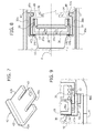
- FIG. 7 is a schematic perspective view of a bottom retention element belonging to the delivery assembly of FIG. 4 ;
- FIGS. 8 and 9 are enlarged details of FIGS. 5 and 6 , respectively;
- FIGS. 10 and 11 are views similar to those of FIG. 6 , regarding two different positions assumed by an injector device in the course of operation of the delivery assembly of FIG. 4 ;
- FIGS. 12 and 13 are views similar to those of FIGS. 5 and 6 , respectively, with the delivery assembly in a condition of infusion;
- FIG. 14 is an enlarged detail of FIG. 12 ;
- FIG. 15 is a view similar to that of FIG. 5 , with the delivery assembly in an end-of-cycle position.
- references to “an embodiment” or “one embodiment” in the framework of the present description is intended to indicate that a particular configuration, structure, or characteristic described in relation to the embodiment is comprised in at least one embodiment.
- phrases such as “in an embodiment” or “in one embodiment” and the like that may be present in various points of the present description do not necessarily refer to one and the same embodiment.
- particular conformations, structures or characteristics may be combined in any adequate way in one or more embodiments.
- FIGS. 1 and 2 illustrate, merely by way of example, a cartridge that can be used in a machine according to the present invention.
- Said cartridge designated as a whole by 10 , is of a type basically known and is described herein merely to facilitate understanding of one embodiment of the present invention.
- the cartridge 10 contains a dose 12 of at least one substance that can form a liquid product via water and/or steam.
- the dose 12 can be constituted by powdered coffee, or by another precursor of a liquid product, such as, for example, a beverage, tea, powdered chocolate, or chocolate in granular form, products for the preparation of broths, soups, drinks and infusions of various nature. Said list is to be understood as merely providing a non-imperative example. In what follows, for simplicity, reference will be made to the preparation of coffee, with the dose 12 that is thus understood as being constituted by powdered coffee.
- the cartridge 10 which is as a whole shaped substantially like a tray or small cup in which the dose 12 is located, there may be distinguished:
- the cartridge 10 is a hermetically closed cartridge, with the wall 16 that is constituted by a sealing lamina.
- the invention can in any case be used also in combination with cartridges in which the bottom wall and/or the closing wall are previously provided with holes.
- the wall or lamina 16 is connected in a fluid-tight way, for example, by heat sealing, to the side wall 14 a of the body 14 of the cartridge, in particular at an outer annular flange 14 c thereof, which surrounds the mouth part of the body 14 .
- the cartridge 10 has an asymmetrical shape, with respect to a plane of the flange 14 c .
- the cartridge 10 has an asymmetrical shape, with respect to a plane passing through the flange 14 c.
- the body 14 is shaped like a cup or tray diverging from the bottom wall 14 b towards the end closed by the sealing lamina 16 .
- said diverging conformation is frustoconical, even though this is not imperative in so far as the cartridge 10 can as a whole be of different shapes, for example, cylindrical, prismatic, frusto-pyramidal, etc.
- the bottom wall 14 b is shaped like a concave vault, with the concavity of said vault directed towards the outside of the cartridge 10 .
- the choice of said conformation is not imperative in so far as the cartridge 10 could have, for example, a bottom wall 14 b shaped like a vault with its concavity facing the inside of the cartridge 10 , or else a bottom wall 14 b that is plane or substantially plane.
- Designated as a whole by 20 in FIG. 3 is a machine for the preparation of liquid products that uses a delivery assembly according to the invention, designed to use a cartridge 10 , for example, a cartridge of the type described above with reference to FIGS. 1 and 2 .
- the machine 20 comprises a reservoir 21 for cold water, with an outlet duct 22 , operative on which is a pump 23 , of a type in itself known, for example, an electromagnetic pump. Via the duct 22 the reservoir 21 is connected to an inlet of a boiler 24 , which is also of a type in itself known. An outlet of the boiler 24 is connected to a duct 25 for supplying hot water and/or steam under pressure to an inlet of a distributor device, for example, a distributor, designated by 26 .
- a distributor device for example, a distributor, designated by 26 .
- the distributor 26 When the distributor 26 is in a first operative position (towards the right, as viewed in FIG. 3 ), it sets the duct 25 in communication with a duct 27 that supplies a nozzle 27 a for dispensing hot water and/or steam. When, instead, the distributor 26 is in a second operative position (to the left, as viewed in FIG. 2 ), the duct 25 is set in fluid communication with a duct 28 for supplying hot water under pressure to a delivery assembly according to the invention, designated as a whole by 30 .
- the delivery assembly 30 is a horizontal delivery assembly, which extends as a whole according to a horizontal axis A.
- the duct 25 is in fluid communication with a duct 29 for return of water to the reservoir 21 .
- the delivery assembly 30 has a supporting structure 30 a , which in FIGS. 3 and 4 is exemplified in the form of a frame, located in which is an infusion chamber 31 , designed to house partially a cartridge 10 , and to deliver the liquid product obtained by means of said cartridge, as will emerge hereinafter.
- the chamber 31 which substantially coaxial to the axis A, basically consists of a cup-shaped body, in a stationary position with respect to the structure 30 a , having a side or peripheral wall 31 a , which defines an inner surface of the chamber, which is substantially frustoconical, or has some other shape congruent with that of the side wall 14 a of the cartridges 10 to be used in the machine 20 .
- the cup-shaped body of the chamber 31 then has a bottom wall 31 b .
- the bottom wall 31 b of the chamber 31 is plane or substantially plane, but in alternative embodiments it may be shaped like a concave vault, with concavity facing the inside or the outside of the cup-shaped body.
- the bottom wall 31 b has at least one passage that sets the inside of the chamber 31 in fluid communication with a duct 32 for dispensing the liquid product that can be obtained by means of the cartridge 10 , i.e., in the example considered here, an infusion of coffee.
- a perforating device 33 associated to the bottom wall 31 b is a perforating device 33 , basically comprising one or more tips—preferably an array of tips—facing the inside of the chamber 31 , in a direction substantially parallel to the axis A.
- the tips in question can have a structure provided with one or more axial openings or grooves, designed to enable the liquid product prepared using the cartridge 10 to flow away, according to the modalities described more fully in what follows.
- the arrangement is such that the liquid that flows away from the cartridge 10 , perforated at the bottom by the perforating device 33 , can reach the dispensing duct 32 that traverses the bottom wall 31 b .
- the invention is applicable also to the case of dispensing assemblies for cartridges that have a previously perforated bottom wall, in which case it is not necessary to envisage the perforating device 33 .
- the chamber 31 In its mouth part, the chamber 31 is limited by an annular head edge, designated by 31 c.
- the delivery assembly 30 further comprises an injector device, designated as a whole by 34 and referred to hereinafter for simplicity as “injector”, designed to introduce into a cartridge 10 the pressurized fluid, supplied by means of the duct 28 .
- injector substantially coaxial to the axis A, is mounted displaceable away from and towards a close-up position of coupling with the infusion chamber 31 , for the purposes of preparation of a liquid product, as will emerge hereinafter.
- the relative movement between the chamber and the injector is obtained by causing the injector to translate linearly with respect to the chamber.
- the duct 28 is preferably a flexible pipe or hose, and the displacement of the injector 34 in the two opposite directions indicated by the arrow F 1 is obtained by means of an actuation system, designated as a whole by 35 .
- the actuation system 35 comprises a substantially toggle-like mechanism, which can, for example, be operated manually by a user via a purposely provided lever (not represented).
- the reciprocating displacement of the injector 34 according to the arrow F 1 can in any case be obtained according to any modality known in the sector, for example, using a system actuated by a suitable electromechanical or hydraulic actuator (for example, a hydraulic cylinder of a known type, having a piston substantially coaxial to the axis A; a hydraulic cylinder of this sort can possibly be controlled via a pressure of water generated by the pump 23 itself).
- a suitable electromechanical or hydraulic actuator for example, a hydraulic cylinder of a known type, having a piston substantially coaxial to the axis A; a hydraulic cylinder of this sort can possibly be controlled via a pressure of water generated by the pump 23 itself).
- operatively associated to the injector 34 is a one-way valve (not represented), designed to open only when the pressure in the duct 28 has reached a given value.
- a valve can be integrated within the injector 34 or else be set outside it.
- the injector 34 comprises a main body 36 connected to the actuation system 35 , having a cavity 36 a , preferably generally cylindrical, coaxial to the body itself, in its part facing the chamber 31 .
- a perforating device 37 operatively housed inside the cavity 36 a is a perforating device 37 , mounted in a stationary position in the cavity 36 a itself.
- the perforating device 37 basically comprises one or more tips—preferably an array of tips—facing the mouth of the chamber 31 and substantially parallel to the axis A.
- the tips in question can have, for example, a structure provided with at least one axial opening, similar to syringe needles, in order to enable supply of pressurized fluid into the cartridge 10 , after perforation of the lamina 16 ( FIGS. 1 and 2 ).
- the arrangement is such that the pressurized fluid that is supplied by means of the duct 28 to the body 36 can, after perforation of the sealing lamina 16 of the cartridge, penetrate into the cartridge itself.
- the invention can be applied also to the case of dispensing assemblies provided for cartridges that have a previously perforated closing wall, in which case the presence of the perforating device 37 is not necessary.
- the cylindrical cavity 36 a is closed by a movable circular plate 38 , coaxial to the axis A, provided with holes (not indicated) aligned or substantially coaxial to the tips 37 a .
- the plate 38 has a cylindrical wall 38 a that is slidable in a fluid-tight way towards the inside of the chamber 36 a , countered by the elastic reaction of a spring 39 .
- the cavity 36 a is shaped so as to define peripherally a seat for housing one end of the spring 39 , the other end of which bears upon the leading end of the wall 38 a of the plate 38 .
- at least one sealing element such as an annular gasket (not indicated).
- the wall 38 a of the plate defines arrests that are to co-operate with fixed arrests, fixed with respect to the main body 36 of the injector 34 or to the perforating device 37 .
- the aforesaid arrests (not indicated), in addition to preventing the plate 38 from sliding out at the front from the cavity 36 a , are sized and positioned in such a way that the front surface of the plate itself is held by the spring 39 substantially flush with the front edge of the main body 36 of the injector 34 (see, for example, FIG. 9 ).
- the dimensions of the plate 38 with the corresponding wall 38 a , of the cavity 36 a and of the tips 37 a are such that, when at rest, the plate 38 is held by the spring 39 in an advanced position, where each tip 37 a engages, or is substantially coaxial to, a respective hole of the plate itself, but without coming out thereof.
- the thrust on the main body 36 of the injector 34 exerted by the actuation system 35 causes the perforating device 37 to be in an extracted condition, where the tips 37 a project from the corresponding holes of the plate 38 , following upon recession of the latter towards the inside of the cavity 36 a , countering the action of the spring 39 .
- the delivery assembly 30 has a loading arrangement, aimed at enabling guided insertion, from above, of a cartridge 10 into the assembly itself.
- the aforesaid loading arrangement includes an upper inlet duct 40 , associated to or integral with the structure 30 a of the assembly 30 , said duct opening substantially in an intermediate area between the chamber 31 and the injector 34 .
- the inlet duct 40 is shaped and has dimensions such as to enable introduction of a cartridge 10 in a direction of loading that is substantially vertical and perpendicular to the axis A (see arrow F 2 in FIG. 4 ), with the corresponding lamina 16 facing the injector 34 .
- the structure 30 a On the opposite side with respect to the inlet duct 40 , the structure 30 a has a lower outlet passage 41 , for discharge from the assembly of the cartridge 10 when the latter is exhausted.
- the inlet duct 40 is shaped and has dimensions such as to guide a cartridge 10 with relative precision up to an area of retention, whilst the outlet passage 41 has wider dimensions than the former, to enable the cartridge 10 to fall freely by gravity out of the assembly 30 .
- the loading arrangement of the delivery assembly 30 is configured to receive the cartridge 10 from above, through the inlet duct 40 , and then keep it in a retention position, substantially coaxial to the axis A, between the chamber 31 and the injector 34 , with the corresponding lamina 16 substantially in contact or preferably only slightly spaced away from the front surface of the plate 38 of the injector 34 .
- the loading arrangement comprises retention means that are capable of assuming a condition of retention and a condition of release of a cartridge 10 .
- retention means that are capable of assuming a condition of retention and a condition of release of a cartridge 10 .
- guiding means configured so as to guide the cartridge up to the aforesaid retention position.
- switching of the retention means between the aforesaid two conditions is determined by the relative movement between the chamber 31 and the injector 34 , in particular by the displacement of the injector with respect to the chamber.
- the aforesaid retention means are carried by the injector 34 and can translate therewith.
- the aforesaid switching between the conditions of retention and of release is determined by the mechanical interaction or interference of said retention means with fixed or stationary elements of the delivery assembly 30 .
- the aforesaid retention means comprise a lower support element 42 , designed to support the cartridge 10 from beneath; said element is mounted movable on the bottom part of the injector 34 , i.e., the part facing the outlet duct 41 .
- the lower support element 42 has a substantially L-shaped plate-like body, with a vertical portion 42 a and a horizontal portion 42 b , the upper surface of which has a, preferably but not necessarily hemispherical, projection 43 .
- the horizontal portion 42 b has two axial cuts, so as to define substantially three tabs, the central one of which, designated by 42 c , is at least slightly flexible and provided with the projection 43 .
- the main body 36 of the injector 34 has, in a front region thereof, a seat 44 —for example, constituted by a slit parallel to the axis A—in the area of which the horizontal portion 42 b of the bottom support element 42 is linearly slidable.
- a lower surface of the main body 36 facing the horizontal portion 42 b of the support 42 , has a notch 45 , where the projection 43 is designed to engage.
- a reverse arrangement is possible, with the notch 45 made on the element 42 and the projection 43 made on the wall of the body 36 .
- the vertical portion 42 a of the support element 42 always remains on the outside of the seat 44 , generally facing, on one side, the chamber 31 and, on the opposite side, a front edge of the body 36 , appropriately provided with a recess in an area corresponding to the aforesaid vertical portion 42 a .
- said vertical portion 42 a is sized in such a way that its upper end, designated by 42 ′ in FIG. 7 , is substantially flush, horizontally, with respect to the peripheral surface of the plate 38 of the injector 34 , as may be clearly seen in FIG. 9 .
- a first stop element is provided, designated by 46 a (see FIG. 4 ), upon which the front end of the support 42 (its vertical portion 42 a ) can come to bear.
- a second stop element is provided, designated by 46 b , on which the rear end of the support element 42 (i.e., of the tab 42 c ) can come to bear.
- the aforesaid stop elements 46 a and 46 b are integral with or fixed with respect to the structure 30 a , but they can evidently be made or associated to other stationary parts of the delivery assembly 30 or of the machine 20 .
- the projection 43 and the notch 45 of the example form coupling means here of a substantially snap-type—designed to keep—in a respective operative condition—the support element 42 in an advanced position in the course of the movement of approach of the injector 34 towards the chamber 31 so as to support the cartridge 10 at the bottom.
- Said coupling means can be switched between the aforesaid operative condition and a respective inoperative condition following upon mechanical interference between the support element 42 and the two stop elements 46 a and 46 b .
- the aforesaid coupling means could have a configuration different from the one exemplified here: for example, the projection 43 could be replaced by a ball or other member forced by a spring, designed for engagement with the notch 45 .
- the aforesaid guiding means comprise two lateral elements, designated by 47 , hereinafter defined only for simplicity as “jaws”.
- the jaws are not hinged or anyway swinging with respect to the injector 34 to be capable of assuming a closed condition and an open out condition: in the preferred embodiment of the invention, the jaws 47 are in a fixed position on the injector 34 .
- the jaws 47 are set substantially symmetrically on opposite sides of the axis A and are supported directly by the injector 34 , substantially in cantilever fashion, so as to extend in length along the two opposite sides of the injector 34 , i.e., substantially in the direction of the axis A.
- the jaws 47 are constrained, preferably in a rear region thereof, to a respective joint pin 47 a , carried by the main body 36 of the injector 34 .
- the front regions of the jaws 47 each define at least one first appendage or tooth 47 b , projecting in a radial direction, i.e., towards the axis A.
- the jaws 47 are shaped and sized in such a way that a rear face of the teeth 47 b generally faces the front edge of the main body 36 of the injector 34 (see, for example, FIG. 8 ), at a short distance therefrom, as well as facing, for a short stretch thereof, also the front surface of the plate 38 , at a slight distance therefrom.
- the shape shown for the guiding elements represented by the jaws 47 is not indispensable, provided that—for example—the guiding elements could have a different shape or be directly defined in the body of the injector 34 ; for example, the guiding means could comprise only the fixed teeth 47 b , defined in or associated to the body 36 of the injector 34 .
- a cartridge 10 is introduced from above into the inlet duct 40 , according to the arrow F 2 of FIG. 4 and pushed slightly downwards.
- Introduction is preferably manual, but may also be obtained by means of an automated mechanism, according to a technique in itself known.
- the injector 34 In the loading step, with the actuation system 35 inactive, the injector 34 is in a respective withdrawn position of loading, where the front of the injector itself is substantially flush with the inlet duct 40 (see, for example, FIGS. 4 and 5 ). In said condition, the lower support element 42 is positioned in such a way that its projection 43 is engaged in the corresponding seat 45 (see FIG. 9 ).
- the inlet duct 40 is shaped and sized so as to guide the cartridge 10 with relative precision in its movement downwards.
- the cartridge 10 descends to the point where the outer edge of its flange 14 c bears upon the upper surface of the vertical portion 42 a of the lower support element 42 , as may be seen, for example, in FIG. 8 .
- the flange 14 c of the cartridge penetrates into the gap existing between the teeth 47 b of the jaws 47 and the front surface of the injector, in particular of its plate 38 (see FIG. 8 ).
- the cartridge 10 is supported vertically by the lower support element 42 and constrained transversely by the jaws 47 in a position of loading or retention, where the cartridge 10 is generally coaxial to the axis A, with the sealing lamina close to or up against the front surface of the plate 38 .
- the cycle of operation of the machine envisages then actuation of the actuation system 35 , which brings about advance of the injector 34 towards the chamber 31 .
- the main body 36 of the injector 34 draws along with it the lower support element 42 , which remains in its bottom position for supporting the cartridge 10 .
- the jaws 47 are in a fixed position with respect to the body of the injector 34 , and movable therewith: therefore, during the advancement of the injector 34 the jaws 47 continue to laterally constrain the cartridge 10 .
- the cartridge 10 cannot penetrate further into the chamber 31 .
- the peripheral region of the bottom wall 14 b of the cartridge 10 bears upon the bottom wall 31 b of the chamber 31 ( FIG. 4 ) or on a peripheral region of the first perforating device 33 ( FIG. 4 ) not provided with tips (for example, in the case of the bottom wall 14 b with concavity as represented in FIG. 2 ) in such a way that the bottom of the cartridge is not perforated.
- the bottom wall of the cartridge bears upon the tips of the first perforating device 33 ( FIG.
- the cartridge 10 cannot penetrate further into the chamber 31 .
- the injector 34 continues in any case to advance, and this causes yielding of the spring 39 ( FIG. 4 ), and then recession of the plate 38 bearing upon the lamina 16 of the cartridge 10 .
- Said recession, and the simultaneous advance of the main body 36 of the injector 34 has the consequence that the tips 37 a of the second perforating device 37 ( FIG. 4 ) come out of the corresponding holes of the plate 38 and perforate the lamina 16 of the cartridge, up to a position of maximum advance of the injector 34 (see FIGS. 12 and 13 ). Once said position is reached the actuation system 35 is no longer active.
- the outer profile of the body defining the chamber 31 is preferably shaped so as to enable in any case the passage of the jaws 47 without any interference or significant interference during the advancement, that is with the teeth 47 b that go beyond the front edge 31 c without enter into contact therewith, for the purpose of attaining the aforesaid position of maximum advance.
- the front part of the cup-shaped body of the chamber 31 which defines the front edge 31 c ( FIG. 4 )—has a restricted diameter, i.e., smaller than that of the flange of the cartridge 10 .
- the cup-shaped body may be provided with axial grooves capable of receiving the part of the jaws that frontally projects from the injector 34 , here represented by the teeth 47 b , when such a part goes beyond, while advancing, the front edge 31 c of the chamber 31 .
- the pressurized fluid is next forced into the cartridge 10 , perforated by means of the tips 37 a of the second perforating device in order to obtain the infusion with the powdered product (coffee, in the example considered) contained in the cartridge 10 .
- the plate 38 is preferably configured, in a way in itself known, to provide fluid tightness with respect to the lamina 16 , in the course of introduction into the latter of the pressurized fluid. In the case where the bottom of the cartridge 10 had already been previously perforated by the tips of the first perforating device 33 , the liquid product generated by the infusion can flow away through the dispensing duct 32 towards a collecting container.
- the pump 23 that sends the hot water under pressure into the cartridge 10 is then deactivated, for example, manually, and a step of discharge of the cartridge 10 can be started.
- the actuation system 35 is operated to bring the injector 34 back into the initial position of FIGS. 5 and 6 .
- Recession of the injector 34 proceeds until the initial condition of the cycle is reached (illustrated in FIG. 15 ). Shortly before reaching the final condition of FIG. 15 , the rear region of the lower support element 42 comes to bear upon the stop element 46 b (see FIGS. 4 and 9 ). The subsequent further recession of the injector 34 thus causes a further sliding of the support element 42 in the corresponding seat 44 , opposite to the previous one, up to engagement of the projection 43 in the corresponding notch 45 . In this way, the support element 42 advances with respect to the front surface of the plate 38 of the injector 34 , returning to the starting position (visible in FIGS. 9 and 15 ), with the corresponding vertical portion 42 an in an operative position for supporting a new cartridge 10 vertically.
- the assembly 30 according to the invention is simple to produce, reliable and compact.
- the support of the cartridge 10 following upon its loading and in the course of its advance towards the infusion chamber 31 , is provided by the lower support element 42 , the jaws 47 performing in this steps basically functions of guide and lateral constraint of the cartridge itself.
- the jaws 47 can have very reduced dimensions and do not require any driving arrangement or elastic elements, being the jaws in a fixed position on the injector 34 .
- the lower support element 42 has a minimum bulk and does not require any complicated actuation system and/or including elastic elements.
- the perforation of the bottom wall 14 b instead of occurring following upon introduction of a pressurized fluid into the cartridge 10 , can also intervene “cold” following upon an action of perforation by the tips of the bottom perforating device 33 , before, together with, or after perforation of the sealing lamina 16 by the tips 37 a of the top perforating device 37 , even before inflow of fluid into the cartridge 10 occurs.
- the cartridges that can be used in the machine provided with the assembly according to the invention can also be of the type where the bottom of the corresponding body has one or more pre-formed passages, which are also closed by a filtering or impermeable film but designed to tear once a given pressure in the cartridge itself is reached.
- the infusion chamber 31 can evidently be without the corresponding perforating device 33 .
- the body 36 of the injector 34 , the perforating device 37 , and the plate 38 may of course have shapes different from those exemplified in the figures, without this adversely affecting their function.
Landscapes
- Engineering & Computer Science (AREA)
- Food Science & Technology (AREA)
- Life Sciences & Earth Sciences (AREA)
- Chemical & Material Sciences (AREA)
- Polymers & Plastics (AREA)
- Mechanical Engineering (AREA)
- Health & Medical Sciences (AREA)
- Nutrition Science (AREA)
- Infusion, Injection, And Reservoir Apparatuses (AREA)
- Apparatus For Making Beverages (AREA)
- Feeding, Discharge, Calcimining, Fusing, And Gas-Generation Devices (AREA)
- Treatment Of Fiber Materials (AREA)
- Filling Of Jars Or Cans And Processes For Cleaning And Sealing Jars (AREA)
Applications Claiming Priority (4)
| Application Number | Priority Date | Filing Date | Title |
|---|---|---|---|
| ITTO2012A0249 | 2012-03-20 | ||
| IT000249A ITTO20120249A1 (it) | 2012-03-20 | 2012-03-20 | Gruppo erogatore per macchine per la preparazione di prodotti liquidi tramite cartucce |
| ITTO2012A000249 | 2012-03-20 | ||
| PCT/IB2013/051543 WO2013140282A1 (fr) | 2012-03-20 | 2013-02-26 | Ensemble de distribution pour machines pour la préparation de produits liquides par l'intermédiaire de cartouches |
Publications (2)
| Publication Number | Publication Date |
|---|---|
| US20150072057A1 US20150072057A1 (en) | 2015-03-12 |
| US9398827B2 true US9398827B2 (en) | 2016-07-26 |
Family
ID=46001514
Family Applications (1)
| Application Number | Title | Priority Date | Filing Date |
|---|---|---|---|
| US14/386,569 Active US9398827B2 (en) | 2012-03-20 | 2013-02-26 | Delivery assembly and method for preparing liquid products via cartridges |
Country Status (9)
| Country | Link |
|---|---|
| US (1) | US9398827B2 (fr) |
| EP (1) | EP2827752B1 (fr) |
| CN (1) | CN104203055B (fr) |
| AU (1) | AU2013237121B2 (fr) |
| CA (1) | CA2864971C (fr) |
| IL (1) | IL234253B (fr) |
| IT (1) | ITTO20120249A1 (fr) |
| PL (1) | PL2827752T3 (fr) |
| WO (1) | WO2013140282A1 (fr) |
Families Citing this family (12)
| Publication number | Priority date | Publication date | Assignee | Title |
|---|---|---|---|---|
| GB2489409B (en) | 2011-03-23 | 2013-05-15 | Kraft Foods R & D Inc | A capsule and a system for, and a method of, preparing a beverage |
| ITTO20110509A1 (it) * | 2011-06-09 | 2012-12-10 | Lavazza Luigi Spa | Gruppo erogatore per macchine per la preparazione di prodotti liquidi tramite cartucce |
| USD697797S1 (en) * | 2012-09-12 | 2014-01-21 | Kraft Foods R&D, Inc. | Beverage cartridge |
| WO2015140686A1 (fr) | 2014-03-19 | 2015-09-24 | Luigi Lavazza S.P.A. | Machine pour la preparation de produits liquides, en particulier au moyen de capsules |
| US20170081112A1 (en) | 2014-03-19 | 2017-03-23 | Luigi Lavazza S.P.A. | Capsule for the preparation of a liquid food product via a brewing machine |
| CN106535725B (zh) | 2014-03-19 | 2019-06-21 | 路易吉·拉瓦扎股份公司 | 用于特别是通过胶囊来制备液体产品的机器 |
| EP3200660B1 (fr) | 2014-09-29 | 2023-08-23 | Luigi Lavazza S.p.A. | Ensemble de distribution pour machines pour la préparation de produits alimentaires liquides |
| US10450131B2 (en) | 2014-10-01 | 2019-10-22 | Kraft Foods Group Brands Llc | Coffee pod |
| ITUB20155069A1 (it) * | 2015-10-22 | 2017-04-22 | Caffitaly System Spa | Apparecchiatura per la preparazione di bevande mediante il passaggio di acqua calda in una capsula contenente una sostanza alimentare |
| IT201900012381A1 (it) | 2019-07-19 | 2021-01-19 | Lavazza Luigi Spa | Sistema, macchina e contenitore per la preparazione di prodotti alimentari fluidi |
| IT201900012390A1 (it) | 2019-07-19 | 2021-01-19 | Lavazza Luigi Spa | Macchina, sistema e metodo per la preparazione di prodotti alimentari fluidi |
| IT201900012396A1 (it) | 2019-07-19 | 2021-01-19 | Lavazza Luigi Spa | Contenitore, sistema e metodo per la preparazione di prodotti alimentari fluidi |
Citations (7)
| Publication number | Priority date | Publication date | Assignee | Title |
|---|---|---|---|---|
| US5197374A (en) * | 1990-07-27 | 1993-03-30 | Nestec S.A. | Apparatus for extracting cartridges containing coffee |
| FR2713905A1 (fr) | 1993-12-20 | 1995-06-23 | Cafes Cie Mediterraneenne | Machine automatique pour la préparation d'infusions de boissons chaudes. |
| US6955116B2 (en) * | 2003-06-13 | 2005-10-18 | Robert Hale | Beverage dispensing machine including cartridge ejector assembly |
| US7063238B2 (en) * | 2001-06-29 | 2006-06-20 | Robert Hale | Cartridge ejector for a beverage dispensing machine |
| US20070202237A1 (en) * | 2004-10-25 | 2007-08-30 | Alfred Yoakim | Capsule with biasing sealing member |
| WO2008096385A1 (fr) | 2007-02-07 | 2008-08-14 | Saeco Ipr Limited | Dispositif d'infusion pour préparer des boissons à partir de capsules jetables avec un dispositif de centrage de capsule |
| WO2010032271A1 (fr) | 2008-09-18 | 2010-03-25 | Saeco Ipr Limited | Dispositif d'infusion pour machines à café et appareils similaires |
Family Cites Families (4)
| Publication number | Priority date | Publication date | Assignee | Title |
|---|---|---|---|---|
| ITTO20040476A1 (it) | 2004-07-09 | 2004-10-09 | Sgl Italia Srl | Metodo per la preparazione di una bevanda a partire da materiale in polvere disposto in una capsula sigillata. |
| ITFI20060194A1 (it) * | 2006-08-04 | 2008-02-05 | Saeco Ipr Ltd | Dispositivo di infusione per la preparazione di bevande da capsule monodose |
| CN201044719Y (zh) | 2007-06-15 | 2008-04-09 | 宁波三A集团电器有限公司 | 咖啡机中咖啡包的自动脱落机构 |
| CN100544647C (zh) | 2007-06-15 | 2009-09-30 | 宁波三A集团电器有限公司 | 咖啡机中咖啡包的自动脱落机构 |
-
2012
- 2012-03-20 IT IT000249A patent/ITTO20120249A1/it unknown
-
2013
- 2013-02-26 WO PCT/IB2013/051543 patent/WO2013140282A1/fr not_active Ceased
- 2013-02-26 US US14/386,569 patent/US9398827B2/en active Active
- 2013-02-26 CA CA2864971A patent/CA2864971C/fr active Active
- 2013-02-26 AU AU2013237121A patent/AU2013237121B2/en active Active
- 2013-02-26 EP EP13716423.2A patent/EP2827752B1/fr active Active
- 2013-02-26 CN CN201380015370.6A patent/CN104203055B/zh active Active
- 2013-02-26 PL PL13716423T patent/PL2827752T3/pl unknown
-
2014
- 2014-08-21 IL IL234253A patent/IL234253B/en active IP Right Grant
Patent Citations (7)
| Publication number | Priority date | Publication date | Assignee | Title |
|---|---|---|---|---|
| US5197374A (en) * | 1990-07-27 | 1993-03-30 | Nestec S.A. | Apparatus for extracting cartridges containing coffee |
| FR2713905A1 (fr) | 1993-12-20 | 1995-06-23 | Cafes Cie Mediterraneenne | Machine automatique pour la préparation d'infusions de boissons chaudes. |
| US7063238B2 (en) * | 2001-06-29 | 2006-06-20 | Robert Hale | Cartridge ejector for a beverage dispensing machine |
| US6955116B2 (en) * | 2003-06-13 | 2005-10-18 | Robert Hale | Beverage dispensing machine including cartridge ejector assembly |
| US20070202237A1 (en) * | 2004-10-25 | 2007-08-30 | Alfred Yoakim | Capsule with biasing sealing member |
| WO2008096385A1 (fr) | 2007-02-07 | 2008-08-14 | Saeco Ipr Limited | Dispositif d'infusion pour préparer des boissons à partir de capsules jetables avec un dispositif de centrage de capsule |
| WO2010032271A1 (fr) | 2008-09-18 | 2010-03-25 | Saeco Ipr Limited | Dispositif d'infusion pour machines à café et appareils similaires |
Non-Patent Citations (2)
| Title |
|---|
| International Search Report for PCT/IB2013/051543 mailed May 27, 2013. |
| Written Opinion of the International Searching Authority for PCT/IB2013/051543 mailed May 27, 2013. |
Also Published As
| Publication number | Publication date |
|---|---|
| WO2013140282A1 (fr) | 2013-09-26 |
| PL2827752T3 (pl) | 2016-07-29 |
| IL234253B (en) | 2018-04-30 |
| CN104203055A (zh) | 2014-12-10 |
| CA2864971A1 (fr) | 2013-09-26 |
| ITTO20120249A1 (it) | 2013-09-21 |
| US20150072057A1 (en) | 2015-03-12 |
| AU2013237121B2 (en) | 2017-02-23 |
| AU2013237121A1 (en) | 2014-09-11 |
| EP2827752A1 (fr) | 2015-01-28 |
| EP2827752B1 (fr) | 2016-01-20 |
| CA2864971C (fr) | 2019-01-15 |
| CN104203055B (zh) | 2017-03-15 |
Similar Documents
| Publication | Publication Date | Title |
|---|---|---|
| US9596955B2 (en) | Delivery assembly for machines for preparing liquid products via cartridges | |
| EP2827752B1 (fr) | Ensemble de distribution pour machines pour la préparation de produits liquides par l'intermédiaire de cartouches | |
| AU2012265877A1 (en) | Delivery assembly for machines for preparing liquid products via cartridges | |
| US9119504B2 (en) | Delivery assembly for machines for preparing liquid products via cartridges | |
| US9186018B2 (en) | Dispensing assembly for machines for the preparation of beverages using capsules | |
| US20110017072A1 (en) | Brewing unit for preparing beverages from single service packages and machines comprising said unit | |
| US10368684B2 (en) | Machine for the preparation of liquid products using capsules | |
| ITTO20110508A1 (it) | Gruppo erogatore per macchine per la preparazione di prodotti liquidi tramite cartucce |
Legal Events
| Date | Code | Title | Description |
|---|---|---|---|
| AS | Assignment |
Owner name: LUIGI LAVAZZA S.P.A., ITALY Free format text: ASSIGNMENT OF ASSIGNORS INTEREST;ASSIGNORS:BUGNANO, LUCA;CABILLI, ALBERTO;REEL/FRAME:033778/0918 Effective date: 20140811 |
|
| STCF | Information on status: patent grant |
Free format text: PATENTED CASE |
|
| MAFP | Maintenance fee payment |
Free format text: PAYMENT OF MAINTENANCE FEE, 4TH YEAR, LARGE ENTITY (ORIGINAL EVENT CODE: M1551); ENTITY STATUS OF PATENT OWNER: LARGE ENTITY Year of fee payment: 4 |
|
| MAFP | Maintenance fee payment |
Free format text: PAYMENT OF MAINTENANCE FEE, 8TH YEAR, LARGE ENTITY (ORIGINAL EVENT CODE: M1552); ENTITY STATUS OF PATENT OWNER: LARGE ENTITY Year of fee payment: 8 |