US9406964B2 - Fuel cell stack - Google Patents
Fuel cell stack Download PDFInfo
- Publication number
- US9406964B2 US9406964B2 US14/371,407 US201214371407A US9406964B2 US 9406964 B2 US9406964 B2 US 9406964B2 US 201214371407 A US201214371407 A US 201214371407A US 9406964 B2 US9406964 B2 US 9406964B2
- Authority
- US
- United States
- Prior art keywords
- stack
- fuel cell
- housing
- face side
- cell stack
- Prior art date
- Legal status (The legal status is an assumption and is not a legal conclusion. Google has not performed a legal analysis and makes no representation as to the accuracy of the status listed.)
- Active, expires
Links
Images

Classifications
-
- H—ELECTRICITY
- H01—ELECTRIC ELEMENTS
- H01M—PROCESSES OR MEANS, e.g. BATTERIES, FOR THE DIRECT CONVERSION OF CHEMICAL ENERGY INTO ELECTRICAL ENERGY
- H01M8/00—Fuel cells; Manufacture thereof
- H01M8/24—Grouping of fuel cells, e.g. stacking of fuel cells
- H01M8/2465—Details of groupings of fuel cells
- H01M8/247—Arrangements for tightening a stack, for accommodation of a stack in a tank or for assembling different tanks
- H01M8/2475—Enclosures, casings or containers of fuel cell stacks
-
- H—ELECTRICITY
- H01—ELECTRIC ELEMENTS
- H01M—PROCESSES OR MEANS, e.g. BATTERIES, FOR THE DIRECT CONVERSION OF CHEMICAL ENERGY INTO ELECTRICAL ENERGY
- H01M8/00—Fuel cells; Manufacture thereof
- H01M8/24—Grouping of fuel cells, e.g. stacking of fuel cells
- H01M8/2465—Details of groupings of fuel cells
- H01M8/247—Arrangements for tightening a stack, for accommodation of a stack in a tank or for assembling different tanks
- H01M8/248—Means for compression of the fuel cell stacks
-
- Y—GENERAL TAGGING OF NEW TECHNOLOGICAL DEVELOPMENTS; GENERAL TAGGING OF CROSS-SECTIONAL TECHNOLOGIES SPANNING OVER SEVERAL SECTIONS OF THE IPC; TECHNICAL SUBJECTS COVERED BY FORMER USPC CROSS-REFERENCE ART COLLECTIONS [XRACs] AND DIGESTS
- Y02—TECHNOLOGIES OR APPLICATIONS FOR MITIGATION OR ADAPTATION AGAINST CLIMATE CHANGE
- Y02E—REDUCTION OF GREENHOUSE GAS [GHG] EMISSIONS, RELATED TO ENERGY GENERATION, TRANSMISSION OR DISTRIBUTION
- Y02E60/00—Enabling technologies; Technologies with a potential or indirect contribution to GHG emissions mitigation
- Y02E60/30—Hydrogen technology
- Y02E60/50—Fuel cells
Definitions
- Exemplary embodiments of the invention relate to a fuel cell stack.
- Fuel cell units convert chemical energy into electrical energy.
- a fuel cell unit is customarily composed of a membrane electrode unit having a proton-conductive membrane, and as electrodes, an anode and a cathode in the form of gas diffusion electrodes, the membrane being situated between the anode and the cathode, and the membrane electrode unit being situated between two bipolar plates, and a bipolar plate in each case being situated between two adjacent fuel cell units.
- the stacked fuel cell units are generally situated in a housing, which is preferably situated between end plates of the fuel cell stack.
- at least one side of the end plates is accessible in such a way that a force-fit connection to a holder or support frame, such as a vehicle body, may be established.
- the height of a fuel cell stack having a predefined number of fuel cell units may vary due to thickness tolerances of the bipolar plates, the membrane electrode units and/or the seals, for example.
- the thickness deviations of the individual components vary, for example, in a range from several hundredths of a millimeter to several tenths of a millimeter. Since the individual tolerances of the components are cumulative, the height of the fuel cell stack containing several hundred fuel cell units, for example, may deviate greatly from a target height. For example, tolerances in the range of ⁇ 5 millimeters, in individual cases even ⁇ 17 millimeters, are known. As a result, the height of each housing must be individually adapted to the height of the fuel cell stack.
- Japanese patent document JP 2009170169 discloses a fuel cell stack situated in a housing having a cover element on its longitudinal sides, and is closed off on an end-face side by an end plate.
- the cover element and the end plate extend in parallel in sections, and a seal is situated in the section extending in parallel.
- Exemplary embodiments of the present invention are directed to a fuel cell stack that is improved over the prior art.
- a fuel cell stack is formed from a plurality of stacked fuel cell units and at least one stack end element, the stacked fuel cell units being surrounded by a housing.
- a frame element is situated on the at least one stack end element and the housing on the end-face side, at least one seal being situated at least between the stack end element and the housing in the area of the frame element.
- the height of the fuel cell stack may vary due to thickness tolerances of the bipolar plates, the membrane electrode units, and/or the seals, for example.
- Such height differences may advantageously be compensated for by means of the frame element.
- the frame element encompasses the stack end element and the housing on the end-face side, so that by means of the at least one seal, seal-tightness between the housing and the stack end element is ensured, even for large height tolerances.
- housings having standardized heights are preferably usable so that installation may be carried out in a cost- and time-efficient manner.
- the frame element is advantageously secured on an end-face side of the stack end element and an end-face side of the housing in a positive-fit, force-fit, and/or integrally joined manner.
- the frame element is preferably mounted in a positive-fit manner on the end-face side of the stack end element and of the housing, the positive fit being assisted by appropriate adhesive bonding and/or screw connections, thus ensuring a mechanically stable connection between the frame element and the stack end element as well as the housing.
- the end-face side of the stack end element is formed by a circumferential angled border of the stack end element, the end-face side of the stack end element extending parallel to the end-face side of the housing and in the stack direction.
- the flexural and torsional strength of the stack end element are advantageously increased by means of the angled border of the stack end element.
- the frame element has a U-shaped profile, the length of the legs of the U-shaped profile corresponding to the length of the angled end-face side of the stack end element, so that the frame element encompasses the end-face side of the stack end element.
- two seals oriented in parallel to one another and having a U-shaped profile in each case are situated between the legs, one of the seals surrounding the end-face side of the stack end element, and the other of the seals surrounding the end-face side of the housing.
- a positive fit and a seal of the stack end element with respect to the housing are thus advantageously possible.
- the seals are preferably molded onto the inner surfaces of the frame element, and therefore are easily producible.
- the U-shaped profile of one of the seals has a design corresponding to the shape and/or external dimensions of the end-face side of the stack end element, and that the U-shaped profile of the other seal has a design corresponding to the external dimensions of the end-face side of the housing.
- the seal for accommodating the end-face side of the housing is formed in such a way that this seal is able to accommodate end-face sides of housings having different heights in a predefinable height range.
- the surface side of the end-face side of the stack end element facing in the direction of the housing is provided with a seal.
- the seal is formed from a plurality of lip seals, for example.
- the seal preferably has recesses for accommodating a clamping device, the clamping device being electrically insulated at least in the area of the recesses.
- the seal which is designed as a lip seal, for example, and the electrically insulated clamping device advantageously cooperate in a sealing manner, and thus prevent penetration of moisture into the area between the fuel cell stack and the housing.
- the combination of the clamping device for clamping the fuel cell stack and the seal of the stack end element with respect to the housing also allows simple and cost-effective production of a sealing system for the fuel cell stack, and also saves installation space.
- insulation is formed, preferably molded, onto the clamping device by means of an injection molding process, for example.
- the seals are made of a rubber, a foam, polyvinyl chloride, thermoplastic polyurethane, and/or a thermoplastic polymer. These electrically insulating materials are characterized by high chemical resistance, high heat resistance, and good corrosion properties.
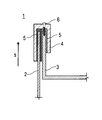
- FIG. 1 schematically shows a sectional illustration of a detail of a fuel cell stack according to the invention in a first exemplary embodiment
- FIG. 2 schematically shows a sectional illustration of a detail of a fuel cell stack according to the invention in a second exemplary embodiment.
- FIG. 1 shows a detail of a fuel cell stack 1 according to the invention in a first exemplary embodiment, the fuel cell stack 1 including a housing 2 , a stack end element 3 , and a frame element 4 .
- the fuel cell stack 1 is composed of the plurality of stacked fuel cell units, not illustrated in greater detail, which are situated in the housing 2 and which are designed, for example, as high-temperature fuel cell units, such as solid oxide fuel cells, or also low-temperature fuel cell units, such as polymer electrolyte fuel cells, whereby polymer electrolyte fuel cells (PEMFC) are preferred.
- high-temperature fuel cell units such as solid oxide fuel cells
- low-temperature fuel cell units such as polymer electrolyte fuel cells, whereby polymer electrolyte fuel cells (PEMFC) are preferred.
- PEMFC polymer electrolyte fuel cells
- the housing 2 is designed, for example, as a housing 2 , which is open at one end and which surrounds the stacked fuel cell units. Ideally, the housing 2 at its open end is adjoined by an end or a surface side of the stack end element 3 , which delimits the fuel cell stack 1 on the end-face side.
- the housing 2 may encompass a portion of a surface side of an end-face side of the stack end element 3 , as illustrated by way of example in FIGS. 1 and 2 .
- the end-face side of the stack end element 3 is formed by a circumferential angled border of the stack end element 3 , the end-face side of the stack end element 3 extending parallel to the end-face side of the housing 2 and in the stack direction s.
- the stack end element 3 delimits the fuel cell stack 1 on the end-face side in the form of an upper end plate.
- the housing 2 may be designed as a housing 2 which is open on both sides, the fuel cell stack 1 having two stack end elements 3 , so that one of the stack end elements 3 delimits an upper end-face side of the fuel cell stack 1 , and the other of the stack end elements 3 delimits a lower end face of the fuel cell stack 1 in the form of a lower end plate (not illustrated). It is particularly preferred that the upper end plate forms the cover, and the lower end plate forms the base, of the housing 2 .
- the stack end element 3 is particularly preferably manufactured in one piece as a metal-plastic hybrid component in the plastic injection molding process.
- the design of the stack end element 3 as a metal-plastic hybrid component allows the beneficial properties of two different materials to be combined.
- clamping forces may be introduced into the fuel cell units over a large surface area, and connecting points to support structures, such as the vehicle body, may be implemented.
- the dimensional stability and heat stability of the metal part are very good.
- a metallic alloy such as steel is also suitable as a metal material.
- a reinforcing part molded onto the metal part.
- an interface to the housing 2 of the fuel cell stack 1 , discharge/supply of gaseous or liquid media from/to the fuel cell stack 1 , and insulation of media, electrically as well as for protection from corrosion, are achievable by means of the reinforcing part.
- the reinforcing part thus optimizes the metal part.
- a thermoplastic material is suited as a plastic or an organic polymer.
- the fuel cell stack 1 has the frame element 4 , which is secured on the end-face side of the stack end element 3 and the end-face side of the housing 2 in a positive-fit, force-fit, and/or integrally joined manner.
- the frame element 4 has a U-shaped profile, whereby two seals 5 oriented in parallel to one another and having a U-shaped profile in each case are situated between the legs.
- One of the seals 5 surrounds the end-face side of the stack end element 3
- the other of the seals 5 surrounds the end-face side of the housing 2 .
- the length of the legs of the U-shaped profile of the seal 5 which encompasses the end-face side of the stack end element 3 , corresponds to the length of the angled end-face side of the stack end element 3 .
- the length of the legs of the U-shaped profile of the seal 5 which encompasses the end-face side of the housing 2 , is predefinable, so that the seal may accommodate end-face sides of housings 2 having different heights in a given height range.
- the end-face side of a housing 2 whose height lies in a minimum range of the given height range, does not contact the web of the leg of the U-shaped profile of the seal 5
- the end-face side of a housing 2 whose height lies in a maximum range of the given height range, may contact the web of the leg of the U-shaped profile of the seal 5 , a sufficient overlap between the seals 5 and the housing 2 being ensured.
- housings 2 having standardized heights are preferably usable so that installation of the fuel cell stack 1 may be carried out in a cost- and time-efficient manner.
- a reduction in the weight of the fuel cell stack 1 is possible, thus profitably allowing a reduction in the weight of a vehicle that is operated using fuel cells, and thus, energy savings during operation of the vehicle.
- the seals 5 are molded onto the inner surfaces of the frame element 4 , for example, and therefore are easily producible. Alternatively, the seals 5 are inserted between the legs of the frame element 4 and additionally adhesively bonded.
- the seals are made of a rubber, a foam, polyvinyl chloride, thermoplastic polyurethane, and/or a thermoplastic polymer. These electrically insulating materials are characterized by high chemical resistance, high heat resistance, and good corrosion properties.
- the frame element 4 is preferably made of a plastic, such as an organic polymer, and during installation of the fuel cell stack 1 is advantageously mounted in a positive-fit manner on the end-face side of the stack end element 3 and of the housing 2 , this positive fit being assisted by a force-fit and/or integral joining in such a way that a mechanically stable connection is ensured between the frame element 4 and the stack end element 3 as well as the housing 2 .
- the frame element 4 is screwed to the stack end element 3 in a force-fit manner by means of a screw 6 .
- the frame element 4 and/or the seals 5 may be adhesively bonded to the end-face side of the stack end element 3 and/or to the end-face side of the housing 2 .
- FIG. 2 A second, alternative embodiment of the invention is shown in FIG. 2 , in which the surface side of the end-face side of the stack end element 3 facing in the direction of the housing 2 is provided with a seal 5 .
- the seal 5 is formed from a plurality of circumferential lip seals 5 . 1 which, for example, are molded onto the surface side of the end-face side of the stack end element 3 .
- the lip seals 5 . 1 may be adhesively bonded to the stack end element 3 .
- the seal 5 is designed as a plurality of ring seals, or as a one-piece circumferential seal.
- the lip seals 5 . 1 are preferably made of the same material as the seals 5 according to the first exemplary embodiment of the invention.
- the lip seals 5 . 1 preferably have recesses for accommodating a clamping device (not shown), the clamping device being electrically insulated at least in the area of the recesses.
- a clamping device (not shown)
- the clamping device transmits tensile forces for clamping the fuel cell stack 1 , via the fuel cell stack, to the fuel cell units stacked in the housing 2 and to the stack end element 3 .
- the lip seals 5 . 1 and the electrically insulated clamping device advantageously cooperate in a sealing manner, and thus prevent penetration of moisture into the area between the fuel cell stack 1 and the housing 2 .
- the combination of the clamping device for clamping the fuel cell stack 1 and the seal of the stack end element 3 with respect to the housing 2 also allows simple and cost-effective production of a sealing system for the fuel cell stack 1 , and also saves installation space.
- insulation is formed, preferably molded, onto the clamping device by means of an injection molding process, for example.
- the frame element 4 is situated on the end-face side of the stack end element 3 and of the housing 2 in a virtually positive-fit manner, and thus advantageously acts as a clamping frame 4 . 1 .
- the frame element 4 designed as a clamping frame 4 . 1 , may have a one-piece or multi-piece design.
- the clamping frame 4 . 1 is screwed to the stack end element 3 in a force-fit manner by means of a screw 6 .
- the clamping frame 4 . 1 may be adhesively bonded to the stack end element 3 and/or to the housing 2 .
- the legs of the clamping frame have insertion chamfers at their free ends.
Landscapes
- Life Sciences & Earth Sciences (AREA)
- Engineering & Computer Science (AREA)
- Manufacturing & Machinery (AREA)
- Sustainable Development (AREA)
- Sustainable Energy (AREA)
- Chemical & Material Sciences (AREA)
- Chemical Kinetics & Catalysis (AREA)
- Electrochemistry (AREA)
- General Chemical & Material Sciences (AREA)
- Fuel Cell (AREA)
Applications Claiming Priority (4)
| Application Number | Priority Date | Filing Date | Title |
|---|---|---|---|
| DE102012000264.5 | 2012-01-10 | ||
| DE102012000264A DE102012000264A1 (de) | 2012-01-10 | 2012-01-10 | Brennstoffzellenstapel |
| DE102012000264 | 2012-01-10 | ||
| PCT/EP2012/005180 WO2013104396A1 (de) | 2012-01-10 | 2012-12-15 | Brennstoffzellenstapel |
Publications (2)
| Publication Number | Publication Date |
|---|---|
| US20150010844A1 US20150010844A1 (en) | 2015-01-08 |
| US9406964B2 true US9406964B2 (en) | 2016-08-02 |
Family
ID=47504804
Family Applications (1)
| Application Number | Title | Priority Date | Filing Date |
|---|---|---|---|
| US14/371,407 Active 2033-07-04 US9406964B2 (en) | 2012-01-10 | 2012-12-15 | Fuel cell stack |
Country Status (6)
| Country | Link |
|---|---|
| US (1) | US9406964B2 (de) |
| EP (1) | EP2803105B1 (de) |
| JP (1) | JP5906326B2 (de) |
| CN (1) | CN104067431B (de) |
| DE (1) | DE102012000264A1 (de) |
| WO (1) | WO2013104396A1 (de) |
Families Citing this family (1)
| Publication number | Priority date | Publication date | Assignee | Title |
|---|---|---|---|---|
| US10199586B2 (en) * | 2016-07-28 | 2019-02-05 | Xerox Corporation | Device comprising dielectric interlayer |
Citations (7)
| Publication number | Priority date | Publication date | Assignee | Title |
|---|---|---|---|---|
| JPH08315854A (ja) | 1995-03-13 | 1996-11-29 | Ngk Insulators Ltd | 高温電池用断熱容器 |
| JP2003323902A (ja) | 2002-05-07 | 2003-11-14 | Hitachi Ltd | 燃料電池発電装置及びこれを用いた携帯機器 |
| US20030235733A1 (en) | 2002-06-24 | 2003-12-25 | Haltiner Karl J. | Solid-oxide fuel cell system having tempering of fuel cell stacks by exhaust gas |
| JP2004335336A (ja) | 2003-05-09 | 2004-11-25 | Nissan Motor Co Ltd | 燃料電池スタック |
| US20060166053A1 (en) * | 2001-11-21 | 2006-07-27 | Badding Michael E | Solid oxide fuel cell assembly with replaceable stack and packet modules |
| JP2009170169A (ja) | 2008-01-11 | 2009-07-30 | Toyota Motor Corp | 燃料電池及びその車載構造 |
| US20100092839A1 (en) | 2008-10-14 | 2010-04-15 | Andreas Kaupert | Fuel cell system |
Family Cites Families (5)
| Publication number | Priority date | Publication date | Assignee | Title |
|---|---|---|---|---|
| DE4442285C1 (de) * | 1994-11-28 | 1996-02-08 | Siemens Ag | Brennstoffzellen und daraus bestehende Brennstoffzellenbatterien |
| JP4621513B2 (ja) * | 2005-02-22 | 2011-01-26 | 本田技研工業株式会社 | 燃料電池スタック |
| JP4928251B2 (ja) * | 2006-12-26 | 2012-05-09 | 本田技研工業株式会社 | 燃料電池スタック |
| JP5231083B2 (ja) * | 2007-06-11 | 2013-07-10 | 本田技研工業株式会社 | 燃料電池スタック |
| US8247131B2 (en) * | 2007-06-11 | 2012-08-21 | Honda Motor Co., Ltd. | Fuel cell stack |
-
2012
- 2012-01-10 DE DE102012000264A patent/DE102012000264A1/de not_active Withdrawn
- 2012-12-15 JP JP2014550644A patent/JP5906326B2/ja active Active
- 2012-12-15 US US14/371,407 patent/US9406964B2/en active Active
- 2012-12-15 EP EP12810087.2A patent/EP2803105B1/de active Active
- 2012-12-15 WO PCT/EP2012/005180 patent/WO2013104396A1/de not_active Ceased
- 2012-12-15 CN CN201280066655.8A patent/CN104067431B/zh active Active
Patent Citations (9)
| Publication number | Priority date | Publication date | Assignee | Title |
|---|---|---|---|---|
| JPH08315854A (ja) | 1995-03-13 | 1996-11-29 | Ngk Insulators Ltd | 高温電池用断熱容器 |
| US20060166053A1 (en) * | 2001-11-21 | 2006-07-27 | Badding Michael E | Solid oxide fuel cell assembly with replaceable stack and packet modules |
| JP2003323902A (ja) | 2002-05-07 | 2003-11-14 | Hitachi Ltd | 燃料電池発電装置及びこれを用いた携帯機器 |
| US20030235733A1 (en) | 2002-06-24 | 2003-12-25 | Haltiner Karl J. | Solid-oxide fuel cell system having tempering of fuel cell stacks by exhaust gas |
| EP1394883A1 (de) | 2002-06-24 | 2004-03-03 | Delphi Technologies, Inc. | Abgasbeheiztes Festelektrolyt Brennstoffzellen System |
| JP2004335336A (ja) | 2003-05-09 | 2004-11-25 | Nissan Motor Co Ltd | 燃料電池スタック |
| JP2009170169A (ja) | 2008-01-11 | 2009-07-30 | Toyota Motor Corp | 燃料電池及びその車載構造 |
| US20100092839A1 (en) | 2008-10-14 | 2010-04-15 | Andreas Kaupert | Fuel cell system |
| DE102008051181A1 (de) | 2008-10-14 | 2010-04-15 | J. Eberspächer GmbH & Co. KG | Brennstoffzellensystem |
Non-Patent Citations (3)
| Title |
|---|
| German-language Written Opinion dated Apr. 8, 2013 (Six (6) pages). |
| International Search Report dated Apr. 8, 2013 (Two (2) pages). |
| Partial English Translation of Japanese Office Action issued in counterpart Japanese Application No. 2014-550644 dated Jun. 30, 2015 (Three (3) pages). |
Also Published As
| Publication number | Publication date |
|---|---|
| JP2015508560A (ja) | 2015-03-19 |
| US20150010844A1 (en) | 2015-01-08 |
| WO2013104396A1 (de) | 2013-07-18 |
| EP2803105A1 (de) | 2014-11-19 |
| CN104067431B (zh) | 2016-05-18 |
| DE102012000264A1 (de) | 2013-07-11 |
| EP2803105B1 (de) | 2016-04-20 |
| JP5906326B2 (ja) | 2016-04-20 |
| CN104067431A (zh) | 2014-09-24 |
Similar Documents
| Publication | Publication Date | Title |
|---|---|---|
| US10026986B2 (en) | Fuel cell stack | |
| US10439247B2 (en) | Fuel cell stack | |
| KR101627631B1 (ko) | 이차 전지 및 그 모듈 | |
| US10886511B2 (en) | Housing for the cell stack of a battery | |
| KR102612762B1 (ko) | 전기 화학적 시스템 | |
| US11038190B2 (en) | Membrane electrode assembly, fuel cell comprising assembly of this type and motor vehicle comprising said fuel cell | |
| KR101416390B1 (ko) | 연료 전지용 금속 분리판, 이를 포함하는 연료 전지 스택 및 이에 적용되는 가스켓 어셈블리 | |
| US20150228987A1 (en) | Membrane electrode assembly and fuel cell comprising assembly of this type | |
| US9490497B2 (en) | Solid polymer electrolyte type fuel cell, and electrolyte membrane-electrode-frame assembly | |
| US9548481B2 (en) | Battery module | |
| JP2014096358A (ja) | 燃料電池スタック | |
| KR102027718B1 (ko) | 연료 전지의 단셀 구조 및 해당 연료 전지 단셀을 적층한 연료 전지의 스택 구조 | |
| US9742012B2 (en) | Fuel cell and manufacturing method thereof having integrated membrane electrode assembly and gas diffusion layer | |
| US20140162166A1 (en) | Fuel cell stack | |
| JP2006049129A (ja) | 燃料電池スタック | |
| KR20080008408A (ko) | 고체산화물 연료전지 스택 | |
| JP6117745B2 (ja) | 燃料電池スタック | |
| KR102447597B1 (ko) | 전기화학적 수소 압축기 | |
| CN107112147B (zh) | 改进接线端的结构的电能储存装置 | |
| BRPI0809976A2 (pt) | Disposição de contato e processo para junção de uma pilha de células de combustível de ao menos uma disposição de contato | |
| US9406964B2 (en) | Fuel cell stack | |
| US20220166117A1 (en) | Cover Assembly for a Cell Housing of a Prismatic Battery Cell With Connection Contacts for a Heating Device, Battery Cell and High-Voltage Battery | |
| KR20170077897A (ko) | 개방형 유로가 구비된 연료전지 스택 | |
| CN104412435A (zh) | 燃料电池单元 | |
| KR101235262B1 (ko) | 고체산화물 연료전지 |
Legal Events
| Date | Code | Title | Description |
|---|---|---|---|
| AS | Assignment |
Owner name: DAIMLER AG, GERMANY Free format text: ASSIGNMENT OF ASSIGNORS INTEREST;ASSIGNORS:STARK, HOLGER;MEX, ULF-MICHAEL;SIGNING DATES FROM 20140806 TO 20140811;REEL/FRAME:033846/0367 |
|
| STCF | Information on status: patent grant |
Free format text: PATENTED CASE |
|
| MAFP | Maintenance fee payment |
Free format text: PAYMENT OF MAINTENANCE FEE, 4TH YEAR, LARGE ENTITY (ORIGINAL EVENT CODE: M1551); ENTITY STATUS OF PATENT OWNER: LARGE ENTITY Year of fee payment: 4 |
|
| AS | Assignment |
Owner name: CELLCENTRIC GMBH & CO. KG, GERMANY Free format text: ASSIGNMENT OF ASSIGNORS INTEREST;ASSIGNOR:DAIMLER AG;REEL/FRAME:058390/0159 Effective date: 20210816 |
|
| MAFP | Maintenance fee payment |
Free format text: PAYMENT OF MAINTENANCE FEE, 8TH YEAR, LARGE ENTITY (ORIGINAL EVENT CODE: M1552); ENTITY STATUS OF PATENT OWNER: LARGE ENTITY Year of fee payment: 8 |