US9408721B2 - Methods and apparatus for an insertion guide device - Google Patents
Methods and apparatus for an insertion guide device Download PDFInfo
- Publication number
- US9408721B2 US9408721B2 US14/322,589 US201414322589A US9408721B2 US 9408721 B2 US9408721 B2 US 9408721B2 US 201414322589 A US201414322589 A US 201414322589A US 9408721 B2 US9408721 B2 US 9408721B2
- Authority
- US
- United States
- Prior art keywords
- elongated plates
- elongated
- plates
- interbody implant
- expandable member
- Prior art date
- Legal status (The legal status is an assumption and is not a legal conclusion. Google has not performed a legal analysis and makes no representation as to the accuracy of the status listed.)
- Active, expires
Links
Images


Classifications
-
- A—HUMAN NECESSITIES
- A61—MEDICAL OR VETERINARY SCIENCE; HYGIENE
- A61F—FILTERS IMPLANTABLE INTO BLOOD VESSELS; PROSTHESES; DEVICES PROVIDING PATENCY TO, OR PREVENTING COLLAPSING OF, TUBULAR STRUCTURES OF THE BODY, e.g. STENTS; ORTHOPAEDIC, NURSING OR CONTRACEPTIVE DEVICES; FOMENTATION; TREATMENT OR PROTECTION OF EYES OR EARS; BANDAGES, DRESSINGS OR ABSORBENT PADS; FIRST-AID KITS
- A61F2/00—Filters implantable into blood vessels; Prostheses, i.e. artificial substitutes or replacements for parts of the body; Appliances for connecting them with the body; Devices providing patency to, or preventing collapsing of, tubular structures of the body, e.g. stents
- A61F2/02—Prostheses implantable into the body
- A61F2/30—Joints
- A61F2/46—Special tools for implanting artificial joints
- A61F2/4603—Special tools for implanting artificial joints for insertion or extraction of endoprosthetic joints or of accessories thereof
- A61F2/4611—Special tools for implanting artificial joints for insertion or extraction of endoprosthetic joints or of accessories thereof of spinal prostheses
-
- A—HUMAN NECESSITIES
- A61—MEDICAL OR VETERINARY SCIENCE; HYGIENE
- A61B—DIAGNOSIS; SURGERY; IDENTIFICATION
- A61B17/00—Surgical instruments, devices or methods
- A61B17/02—Surgical instruments, devices or methods for holding wounds open, e.g. retractors; Tractors
- A61B17/025—Joint distractors
-
- A—HUMAN NECESSITIES
- A61—MEDICAL OR VETERINARY SCIENCE; HYGIENE
- A61F—FILTERS IMPLANTABLE INTO BLOOD VESSELS; PROSTHESES; DEVICES PROVIDING PATENCY TO, OR PREVENTING COLLAPSING OF, TUBULAR STRUCTURES OF THE BODY, e.g. STENTS; ORTHOPAEDIC, NURSING OR CONTRACEPTIVE DEVICES; FOMENTATION; TREATMENT OR PROTECTION OF EYES OR EARS; BANDAGES, DRESSINGS OR ABSORBENT PADS; FIRST-AID KITS
- A61F2/00—Filters implantable into blood vessels; Prostheses, i.e. artificial substitutes or replacements for parts of the body; Appliances for connecting them with the body; Devices providing patency to, or preventing collapsing of, tubular structures of the body, e.g. stents
- A61F2/02—Prostheses implantable into the body
- A61F2/30—Joints
- A61F2/44—Joints for the spine, e.g. vertebrae, spinal discs
- A61F2/4455—Joints for the spine, e.g. vertebrae, spinal discs for the fusion of spinal bodies, e.g. intervertebral fusion of adjacent spinal bodies, e.g. fusion cages
-
- A—HUMAN NECESSITIES
- A61—MEDICAL OR VETERINARY SCIENCE; HYGIENE
- A61B—DIAGNOSIS; SURGERY; IDENTIFICATION
- A61B17/00—Surgical instruments, devices or methods
- A61B17/02—Surgical instruments, devices or methods for holding wounds open, e.g. retractors; Tractors
- A61B17/025—Joint distractors
- A61B2017/0256—Joint distractors for the spine
-
- A—HUMAN NECESSITIES
- A61—MEDICAL OR VETERINARY SCIENCE; HYGIENE
- A61F—FILTERS IMPLANTABLE INTO BLOOD VESSELS; PROSTHESES; DEVICES PROVIDING PATENCY TO, OR PREVENTING COLLAPSING OF, TUBULAR STRUCTURES OF THE BODY, e.g. STENTS; ORTHOPAEDIC, NURSING OR CONTRACEPTIVE DEVICES; FOMENTATION; TREATMENT OR PROTECTION OF EYES OR EARS; BANDAGES, DRESSINGS OR ABSORBENT PADS; FIRST-AID KITS
- A61F2/00—Filters implantable into blood vessels; Prostheses, i.e. artificial substitutes or replacements for parts of the body; Appliances for connecting them with the body; Devices providing patency to, or preventing collapsing of, tubular structures of the body, e.g. stents
- A61F2/02—Prostheses implantable into the body
- A61F2/30—Joints
- A61F2/44—Joints for the spine, e.g. vertebrae, spinal discs
- A61F2/4455—Joints for the spine, e.g. vertebrae, spinal discs for the fusion of spinal bodies, e.g. intervertebral fusion of adjacent spinal bodies, e.g. fusion cages
- A61F2/447—Joints for the spine, e.g. vertebrae, spinal discs for the fusion of spinal bodies, e.g. intervertebral fusion of adjacent spinal bodies, e.g. fusion cages substantially parallelepipedal, e.g. having a rectangular or trapezoidal cross-section
-
- A—HUMAN NECESSITIES
- A61—MEDICAL OR VETERINARY SCIENCE; HYGIENE
- A61F—FILTERS IMPLANTABLE INTO BLOOD VESSELS; PROSTHESES; DEVICES PROVIDING PATENCY TO, OR PREVENTING COLLAPSING OF, TUBULAR STRUCTURES OF THE BODY, e.g. STENTS; ORTHOPAEDIC, NURSING OR CONTRACEPTIVE DEVICES; FOMENTATION; TREATMENT OR PROTECTION OF EYES OR EARS; BANDAGES, DRESSINGS OR ABSORBENT PADS; FIRST-AID KITS
- A61F2/00—Filters implantable into blood vessels; Prostheses, i.e. artificial substitutes or replacements for parts of the body; Appliances for connecting them with the body; Devices providing patency to, or preventing collapsing of, tubular structures of the body, e.g. stents
- A61F2/02—Prostheses implantable into the body
- A61F2/30—Joints
- A61F2/46—Special tools for implanting artificial joints
- A61F2/4603—Special tools for implanting artificial joints for insertion or extraction of endoprosthetic joints or of accessories thereof
-
- A—HUMAN NECESSITIES
- A61—MEDICAL OR VETERINARY SCIENCE; HYGIENE
- A61F—FILTERS IMPLANTABLE INTO BLOOD VESSELS; PROSTHESES; DEVICES PROVIDING PATENCY TO, OR PREVENTING COLLAPSING OF, TUBULAR STRUCTURES OF THE BODY, e.g. STENTS; ORTHOPAEDIC, NURSING OR CONTRACEPTIVE DEVICES; FOMENTATION; TREATMENT OR PROTECTION OF EYES OR EARS; BANDAGES, DRESSINGS OR ABSORBENT PADS; FIRST-AID KITS
- A61F2/00—Filters implantable into blood vessels; Prostheses, i.e. artificial substitutes or replacements for parts of the body; Appliances for connecting them with the body; Devices providing patency to, or preventing collapsing of, tubular structures of the body, e.g. stents
- A61F2/02—Prostheses implantable into the body
- A61F2/30—Joints
- A61F2002/30001—Additional features of subject-matter classified in A61F2/28, A61F2/30 and subgroups thereof
- A61F2002/30108—Shapes
- A61F2002/30199—Three-dimensional shapes
- A61F2002/30224—Three-dimensional shapes cylindrical
- A61F2002/30235—Three-dimensional shapes cylindrical tubular, e.g. sleeves
-
- A—HUMAN NECESSITIES
- A61—MEDICAL OR VETERINARY SCIENCE; HYGIENE
- A61F—FILTERS IMPLANTABLE INTO BLOOD VESSELS; PROSTHESES; DEVICES PROVIDING PATENCY TO, OR PREVENTING COLLAPSING OF, TUBULAR STRUCTURES OF THE BODY, e.g. STENTS; ORTHOPAEDIC, NURSING OR CONTRACEPTIVE DEVICES; FOMENTATION; TREATMENT OR PROTECTION OF EYES OR EARS; BANDAGES, DRESSINGS OR ABSORBENT PADS; FIRST-AID KITS
- A61F2/00—Filters implantable into blood vessels; Prostheses, i.e. artificial substitutes or replacements for parts of the body; Appliances for connecting them with the body; Devices providing patency to, or preventing collapsing of, tubular structures of the body, e.g. stents
- A61F2/02—Prostheses implantable into the body
- A61F2/30—Joints
- A61F2002/30001—Additional features of subject-matter classified in A61F2/28, A61F2/30 and subgroups thereof
- A61F2002/30316—The prosthesis having different structural features at different locations within the same prosthesis; Connections between prosthetic parts; Special structural features of bone or joint prostheses not otherwise provided for
- A61F2002/30535—Special structural features of bone or joint prostheses not otherwise provided for
- A61F2002/30563—Special structural features of bone or joint prostheses not otherwise provided for having elastic means or damping means, different from springs, e.g. including an elastomeric core or shock absorbers
-
- A—HUMAN NECESSITIES
- A61—MEDICAL OR VETERINARY SCIENCE; HYGIENE
- A61F—FILTERS IMPLANTABLE INTO BLOOD VESSELS; PROSTHESES; DEVICES PROVIDING PATENCY TO, OR PREVENTING COLLAPSING OF, TUBULAR STRUCTURES OF THE BODY, e.g. STENTS; ORTHOPAEDIC, NURSING OR CONTRACEPTIVE DEVICES; FOMENTATION; TREATMENT OR PROTECTION OF EYES OR EARS; BANDAGES, DRESSINGS OR ABSORBENT PADS; FIRST-AID KITS
- A61F2/00—Filters implantable into blood vessels; Prostheses, i.e. artificial substitutes or replacements for parts of the body; Appliances for connecting them with the body; Devices providing patency to, or preventing collapsing of, tubular structures of the body, e.g. stents
- A61F2/02—Prostheses implantable into the body
- A61F2/30—Joints
- A61F2002/30001—Additional features of subject-matter classified in A61F2/28, A61F2/30 and subgroups thereof
- A61F2002/30316—The prosthesis having different structural features at different locations within the same prosthesis; Connections between prosthetic parts; Special structural features of bone or joint prostheses not otherwise provided for
- A61F2002/30535—Special structural features of bone or joint prostheses not otherwise provided for
- A61F2002/30579—Special structural features of bone or joint prostheses not otherwise provided for with mechanically expandable devices, e.g. fixation devices
-
- A—HUMAN NECESSITIES
- A61—MEDICAL OR VETERINARY SCIENCE; HYGIENE
- A61F—FILTERS IMPLANTABLE INTO BLOOD VESSELS; PROSTHESES; DEVICES PROVIDING PATENCY TO, OR PREVENTING COLLAPSING OF, TUBULAR STRUCTURES OF THE BODY, e.g. STENTS; ORTHOPAEDIC, NURSING OR CONTRACEPTIVE DEVICES; FOMENTATION; TREATMENT OR PROTECTION OF EYES OR EARS; BANDAGES, DRESSINGS OR ABSORBENT PADS; FIRST-AID KITS
- A61F2/00—Filters implantable into blood vessels; Prostheses, i.e. artificial substitutes or replacements for parts of the body; Appliances for connecting them with the body; Devices providing patency to, or preventing collapsing of, tubular structures of the body, e.g. stents
- A61F2/02—Prostheses implantable into the body
- A61F2/30—Joints
- A61F2002/30001—Additional features of subject-matter classified in A61F2/28, A61F2/30 and subgroups thereof
- A61F2002/30316—The prosthesis having different structural features at different locations within the same prosthesis; Connections between prosthetic parts; Special structural features of bone or joint prostheses not otherwise provided for
- A61F2002/30535—Special structural features of bone or joint prostheses not otherwise provided for
- A61F2002/30594—Special structural features of bone or joint prostheses not otherwise provided for slotted, e.g. radial or meridian slot ending in a polar aperture, non-polar slots, horizontal or arcuate slots
-
- A—HUMAN NECESSITIES
- A61—MEDICAL OR VETERINARY SCIENCE; HYGIENE
- A61F—FILTERS IMPLANTABLE INTO BLOOD VESSELS; PROSTHESES; DEVICES PROVIDING PATENCY TO, OR PREVENTING COLLAPSING OF, TUBULAR STRUCTURES OF THE BODY, e.g. STENTS; ORTHOPAEDIC, NURSING OR CONTRACEPTIVE DEVICES; FOMENTATION; TREATMENT OR PROTECTION OF EYES OR EARS; BANDAGES, DRESSINGS OR ABSORBENT PADS; FIRST-AID KITS
- A61F2/00—Filters implantable into blood vessels; Prostheses, i.e. artificial substitutes or replacements for parts of the body; Appliances for connecting them with the body; Devices providing patency to, or preventing collapsing of, tubular structures of the body, e.g. stents
- A61F2/02—Prostheses implantable into the body
- A61F2/30—Joints
- A61F2/46—Special tools for implanting artificial joints
- A61F2/4603—Special tools for implanting artificial joints for insertion or extraction of endoprosthetic joints or of accessories thereof
- A61F2002/4615—Special tools for implanting artificial joints for insertion or extraction of endoprosthetic joints or of accessories thereof of spacers
-
- A—HUMAN NECESSITIES
- A61—MEDICAL OR VETERINARY SCIENCE; HYGIENE
- A61F—FILTERS IMPLANTABLE INTO BLOOD VESSELS; PROSTHESES; DEVICES PROVIDING PATENCY TO, OR PREVENTING COLLAPSING OF, TUBULAR STRUCTURES OF THE BODY, e.g. STENTS; ORTHOPAEDIC, NURSING OR CONTRACEPTIVE DEVICES; FOMENTATION; TREATMENT OR PROTECTION OF EYES OR EARS; BANDAGES, DRESSINGS OR ABSORBENT PADS; FIRST-AID KITS
- A61F2/00—Filters implantable into blood vessels; Prostheses, i.e. artificial substitutes or replacements for parts of the body; Appliances for connecting them with the body; Devices providing patency to, or preventing collapsing of, tubular structures of the body, e.g. stents
- A61F2/02—Prostheses implantable into the body
- A61F2/30—Joints
- A61F2/46—Special tools for implanting artificial joints
- A61F2/4603—Special tools for implanting artificial joints for insertion or extraction of endoprosthetic joints or of accessories thereof
- A61F2002/4625—Special tools for implanting artificial joints for insertion or extraction of endoprosthetic joints or of accessories thereof with relative movement between parts of the instrument during use
- A61F2002/4628—Special tools for implanting artificial joints for insertion or extraction of endoprosthetic joints or of accessories thereof with relative movement between parts of the instrument during use with linear motion along or rotating motion about an axis transverse to the instrument axis or to the implantation direction, e.g. clamping
Definitions
- the present invention generally relates to medical devices and methods, and more particularly relates to delivery instruments and methods for deploying an interbody fusion implant into an intervertebral disc space.
- interbody fusion implants may be implanted in the intervertebral disc space. These devices facilitate fusion of the adjacent vertebrae together. Depending on the size of the interbody fusion device and the corresponding delivery instrument, a surgeon may have to remove bone from the surrounding vertebrae in order to provide adequate space. Clearly, it would be desirable if bone removal could be minimized or eliminated all together. Moreover, adjacent tissue may also need to be retracted or removed, and it would be desirable to minimize or eliminate this as well. Also, insertion of the implant often requires distraction of the vertebrae, therefore it would be desirable to provide a low profile implant that minimizes the amount of distraction required.
- Newer interbody fusion devices are being developed which have a smaller more compact profile for delivery and a larger expanded profile after deployment.
- the smaller delivery size facilitates delivery, and the larger deployed configuration facilitates support and fusion of the bone. Therefore, it would be desirable to provide improved delivery instruments which can accurately and safely deliver and deploy interbody fusion devices including those that have collapsed configurations for delivery and expanded configurations after deployment. At least some of these objectives will be satisfied by the devices and methods disclosed below.
- the present invention generally relates to medical devices and methods, and more particularly relates to delivery instruments and methods for deploying an interbody fusion implant into an intervertebral disc space.
- a delivery instrument for facilitating the placement of an interbody implant into an intervertebral space of a patient comprises a plurality of elongated plates disposed adjacent one another. Each elongated plate has a proximal portion and a distal portion. The distal portion of each elongated plate is sized and shaped to fit into the intervertebral space, and also the distal portion of each elongated plate is configured to engage a vertebral body in the intervertebral space.
- An expandable member is coupled to the plurality of elongated plates so as to form an enclosed tube for at least a portion of the length of the plurality of elongated plates. The enclosed tube is sized and shaped to receive the interbody implant. The expandable member allows for translation of the plurality of elongated plates relative to one another as the interbody implant passes through the tube.
- the expandable member may be an elastomeric tube that is disposed over the plurality of elongated plates.
- the expandable member may comprise two or more flexible sheets of resilient material that extend from one elongated plate to another elongated plate.
- the plurality of elongated plates may have a geometry that is configured to engage the interbody implant passing through the tube, and the plurality of elongated plates may have a geometry that guides the interbody implant into the intervertebral space.
- the geometry that engages the interbody implant may comprise a plurality of rails extending from the plurality of elongated plates.
- the plurality of elongated plates may be expandable to allow the delivery instrument to expand in one or multiple directions in order to accommodate various sizes of interbody implants.
- the plurality of elongated plates may have a longitudinally oriented slit located therealong, and the slit may be configured to allow the plurality of plates to expand and contract.
- the longitudinally oriented slit may comprise a stress relief feature.
- the plurality of plates may be coupled together adjacent their proximal portion.
- At least one of the plurality of elongated plates may comprise a finger loop adjacent a proximal end thereof, and the finger loop may be configured to facilitate grasping by an operator's finger.
- the delivery instrument may further comprise a stop element disposed adjacent a distal portion of at least one of the plurality of elongated plates. The stop element may be configured to limit insertion of the delivery instrument into the intervertebral space.
- a system for delivering an implant to an intervertebral space of a patient comprises the delivery instrument previously described above as well as an interbody implant.
- a method for delivering an interbody implant into an intervertebral space between adjacent vertebral bodies of a patient comprises providing a delivery instrument having a plurality of elongated plates disposed adjacent one another and coupled together with an expandable member, and advancing the interbody implant along a tube formed by the plurality of elongated plates and the expandable member.
- the method also comprises translating the plurality of elongated plates relative to one another as the interbody implant advances along the tube, ejecting the interbody implant from the delivery device, and returning the elongated plates to an unbiased configuration after the interbody implant has been ejected.
- Translating the plurality of elongated plates may comprise moving the plurality of plates away from one another, or expanding or collapsing the expandable member.
- the expandable member may comprise an elastomeric tube that is disposed over the plurality of elongated plates.
- Advancing the interbody implant may comprise guiding the interbody implant along the tube with a plurality rails extending from the plurality of elongated plates.
- a stress relief feature may be included in one or more of the plurality of elongated plates, and the method may further comprise relieving stress in the delivery instrument as the interbody implant is translated therealong.
- Translating the plurality of elongated plates may comprise expanding or contracting a slit disposed in at least one of the plurality of elongated plates.
- the plurality of elongated plates may be coupled to one another adjacent a proximal portion thereof, and translating the plurality of elongated plates may comprise pivoting the plurality of elongated plates relative to the proximal portion.
- Ejecting may comprise disposing the interbody implant in the intervertebral space.
- the method may further comprise engaging a distal portion of the plurality of elongated plates with the vertebral bodies.
- the method may further comprise grasping the delivery device by inserting one or more fingers in a finger loop disposed on a proximal portion of at least one of the plurality of elongated plates.
- the method may also further comprise advancing the plurality of elongate plates into the intervertebral space, and limiting penetration of the plurality of elongate plates into the intervertebral space. This may be accomplished by engaging a stop element disposed on at least one of the plurality of elongate plates against an edge of at least one of the adjacent vertebral bodies.
- FIG. 1 is a perspective view of an elongated plate component
- FIG. 2 is a perspective view of an insertion guide device, using the elongated plate in FIG. 1 , in the collapsed state;
- FIG. 3 is a perspective view of the insertion guide device in FIG. 2 in an expanded state
- FIG. 4 is a perspective view of an elongated plate component
- FIG. 5 is a perspective view of an insertion guide device, using the elongated plate in FIG. 4 , in the collapsed state;
- FIG. 6 is a perspective view of the insertion guide device in FIG. 5 in an expanded state
- FIG. 7 is a perspective view of an elongated plate component
- FIG. 8 is a perspective view of an insertion guide device, using the elongated plate in FIG. 7 , in the collapsed state;
- FIG. 9 illustrates an interbody implant coupled to the insertion guide device
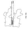
- FIGS. 10A-10F illustrate insertion of the insertion guide device into the intervertebral disc space and delivery of an interbody implant
- FIGS. 11A-11B illustrate a pusher element for pushing an interbody implant from the insertion guide device.
- FIG. 12A illustrates a perspective view of another exemplary embodiment of an elongated plate used in an insertion guide device.
- FIG. 12B is a side view of FIG. 12A .
- FIG. 13A illustrates a perspective view of an insertion guide device using the elongated plate in FIG. 12A and in the collapsed configuration.
- FIG. 13B illustrates the embodiment of FIG. 13A in the expanded configuration.
- FIG. 14 is a perspective view of the insertion guide device of FIG. 13A inserted into the intervertebral space.
- FIG. 15A illustrates a perspective view of another exemplary embodiment of an elongated plate that may be used in an insertion guide device.
- FIG. 15B is a side view of FIG. 15A .
- FIG. 16A illustrates a perspective view of an insertion guide device using the elongated plate in FIG. 15A and FIG. 12A , and in the collapsed configuration.
- FIG. 16B illustrates the embodiment of FIG. 16A in the expanded configuration.
- FIG. 17 illustrates the insertion guide device of FIG. 16A inserted into the intervertebral disc space.
- FIG. 1 shows the elongated plate 20 with optional rails 21 extending outward from the elongated plate, to guide the implant into the disc space.
- the rails 21 extend up to the distal portion 22 of the elongated plate 20 that enters the disc space.
- the rails 21 end prior to the distal portion 22 of the elongated plate 20 in order to decrease the width of the elongated plate 20 that has to pass by the neural elements and into the disc space.
- the rails 21 are set at a distance apart to match the width of the implant being passed through it further optimizing the width of the elongated plate 20 so that it is as narrow as possible (low profile) as it passes by the neural elements.
- Notch 23 is an optional feature in the elongated plate 20 to allow for the engagement of the expandable member 30 .
- This notch 23 prevents the axial migration of the expandable member 30 along the length of the elongated member 20 .
- the elongated plate 20 may be made out of a variety of materials including, but not limited to, metals such as stainless steel or aluminum, carbon fiber, other composite materials, polymers such ABS, and RadelTM.
- FIG. 2 Two of the elongated plates 20 are shown in FIG. 2 joined by an expandable member 30 in one exemplary embodiment of the device.
- the distal portion of the device 31 that enters the disc space is in a collapsed configuration with each distal portion 22 of the elongated plates 20 adjacent or engaged with one another and being positioned such that they can engage the endplates of the adjacent vertebral bodies in a collapsed disc space.
- the expandable member 30 has a distal end 32 that doesn't enter into the disc space, in addition, the proximal end 33 of the expandable member 30 does not extend to the proximal end 24 of the elongated member 20 .
- the expandable member 30 may be made of a variety of different materials including, but not limited to, polyurethane, polyisoprene, and latex.
- the device is shown in an expanded state with the distal end of the device 31 aiding in distraction of the disc space and the expandable member 30 being stretched to accommodate the increased distance between the elongated plates 20 .
- the distal ends of elongated members 20 are separated from one another by a gap and displaced apart relative to the collapsed configuration.
- FIG. 4 shows another exemplary embodiment of the elongated plate 40 .
- the major addition in this embodiment of the design is the ability of the elongated plate 40 to expand to accommodate varying width implants. This expansion is accommodated by the split or slot 43 in the elongated plate 40 that runs from the proximal end 47 to the distal end 42 .
- the split 43 runs out of the lateral edge 45 of the elongated plate 40 allowing for a solid surface within the disc space at the distal end 42 for better distraction of the disc space and a decreased potential for subsidence of the elongated plate 40 into the endplate.
- the rails 41 have a tapered portion 44 that allow for the insertion of a wide implant at the proximal end 47 prior to the expansion of the elongated plate 40 .
- the split 43 in the elongated plate 40 has a stress relief cut 46 near the proximal end 47 .
- the stress relief 46 is a circular through hole in the elongated plate.
- This version of the elongated plate 40 is shown as part of an assembled device in FIG. 5 . In this embodiment of the device, two elongated plates 40 are joined by the expandable member 50 .
- FIG. 5 shows the device in its collapsed state with the little distance between the elongated plates 40 at the distal end of the device 51 .
- This same embodiment of the device is shown in FIG. 6 in an expanded state with a distracted distal end of the construct 51 .
- the top elongated plate is substantially the same as the bottom elongated plate.
- FIG. 7 shows another preferred embodiment of the elongated plate 60 .
- the elongated plates are joined at the proximal end 61 .
- this embodiment has a split 62 or slot to allow for expansion in width, a tapered portion 60 , a lateral run out 65 of the split 62 , and a flat surface that contacts the vertebral end plates at the distal end 66 .
- This embodiment of the elongated plate 60 also has a step 64 to help constrain the expanding member 70 as seen in FIG. 8 .
- FIG. 8 shows the embodiment of the elongated plate 60 with the expanding member 70 covering the distal portion of the device to protect the neural elements and terminating just prior to the distal end of the device 71 that enters the disc space.
- FIG. 9 illustrates an interbody implant 92 coupled to the insertion guide device 94 .
- the interbody implant is in its collapsed configuration, and it may be any of the embodiments disclosed herein, or disclosed in U.S. patent application Ser. No. 14/322,702 filed Jul. 2, 2014 and previously incorporated herein by reference.
- the insertion guide device may be any of the embodiments disclosed in this specification.
- FIGS. 10A-10F illustrate an exemplary method of delivering an interbody implant using an insertion guide device such as those described in this specification.
- the insertion guide device 102 is inserted into the intervertebral disc space between adjacent vertebrae V.
- the elongated plates are in their collapsed configuration.
- the expandable member is advanced toward the vertebrae, but is not inserted into the intervertebral space.
- FIG. 10B the interbody implant 104 is advanced distally out of the insertion guide device 102 until it is exposed from the expandable portion of the insertion guide device and positioned in a desired location between the vertebrae, as illustrated in FIG. 10C .
- FIG. 10D is similar to FIG. 10C but illustrates a longer portion of the insertion guide device.
- FIG. 10E the interbody implant and the insertion guide device have been rotated preferably 90 degrees so that the textured surfaces of the interbody implant are in engagement with the endplates of the vertebrae.
- FIG. 10F is a top view of the interbody implant and insertion guide device with the upper vertebra removed for ease in viewing. Additionally, the interbody implant has been laterally expanded to increase its width.
- the interbody implant and the insertion guide device may be any of the embodiments disclosed herein. Additional details on the interbody implant are disclosed in U.S. patent application Ser. No. 14/322,702 filed Jul. 2, 2014, and previously incorporated herein by reference.
- FIGS. 11A-11B illustrate the pusher element which may be advanced or retracted by an operator to move the interbody implant through the insertion guide device disclosed above.
- the pusher element 1102 includes an elongate shaft with a handle on the proximal end for ease in manipulation.
- a lever 1104 helps lock the pusher to the interbody implant.
- FIG. 11B illustrates the interbody implant 1106 coupled to the pusher element 1102 .
- a leaf spring is disposed under the actuation lever thereby biasing the lever in the up position so that the pusher remains locked with the interbody implant. When the lever is moved, the implant may be decoupled from the pusher.
- the pusher/implant assembly is preferably inserted into the elongated plate assembly for delivery to the intervertebral space.
- FIGS. 12A-12B illustrate another exemplary embodiment of elongated plates that may be used in an insertion guide device.
- FIG. 12A shows an exemplary embodiment of an elongated plate 80 with rails 81 that extend outward from the plate and guide the implant into the disc space. Pre-formed finger loops 82 on the proximal end of the plate allow a user to more easily control the insertion guide device position. Rails 81 end prior to the distal portion 83 of the elongated plate and extend up to the transition 84 to finger loop 82 .
- FIG. 12B illustrates a side view of FIG. 12A .
- FIGS. 13A-13B illustrate an insertion guide device using the elongated plates of FIG. 12A .
- the insertion guide device is illustrated in the collapsed configure.
- Two of the elongated plates 80 are shown joined by an expandable member 90 which may be any of the embodiments of expandable member disclosed herein.
- Expandable member 90 is preferably attached to the top surfaces 91 of elongated plates 80 via an adhesive.
- Expandable member 90 also has a bead 92 to help resist tearing of the expandable member during use.
- the bead may be a rolled up section of the expandable member to increase thickness and resistance to tearing, or it may be a separate material coupled to the expandable member to provide the reinforcement.
- FIG. 13B illustrates the embodiment of FIG. 13A in the expanded configuration.
- FIG. 14 illustrate the insertion guide device of FIG. 13A inserted into the intervertebral disc space.
- the insertion guide device is positioned such that the distal portions 83 of the elongated plates 80 engage the endplates of the adjacent vertebral bodies 95 and 96 .
- the expandable member 90 remains outside of the intervertebral space.
- FIGS. 15A-15B illustrate still another exemplary embodiment of elongated plates that may be used in an insertion guide device.
- FIG. 15A shows an elongated plate 100 with stop feature 101 to prevent the insertion guide device from being inserted too far anteriorly into the disc space.
- the stop 101 is preferably a protrusion which extends out of the plane of the elongated plate.
- Other aspects of the elongated plate are generally the same as the embodiment illustrated in FIG. 12A-12B .
- FIG. 15B is a side view of FIG. 15A .
- FIG. 16A illustrates an exemplary embodiment of an insertion guide device using one elongated plate as illustrated in FIG. 15A with a stop, and another elongated plate as illustrated in FIG. 12A without a stop.
- the embodiment in FIG. 15A is in the collapsed configuration.
- Expandable member 90 joins elongated plates 80 and 90 together.
- Other aspects of the insertion guide device are generally the same as previously described above.
- An alternative embodiment of the insertion guide device may have two elongated plates both having stops. Thus, the insertion guide may have two elongated plates such as those described in FIG. 15A .
- FIG. 16B illustrates the insertion guide device in FIG. 16A in the expanded (also referred to as distracted) configuration.
- FIG. 17 shows the insertion guide device of FIG. 16A inserted into the intervertebral disc space.
- Stop feature 101 engages the edge of superior vertebral body 110 to prevent the insertion guide device from moving further anterior.
- the stop feature may engage the edge of the inferior vertebral body 96 , or in embodiments with two stops, an edge of the inferior and superior vertebral body may be engaged by a stop feature.
Landscapes
- Health & Medical Sciences (AREA)
- Engineering & Computer Science (AREA)
- Biomedical Technology (AREA)
- Life Sciences & Earth Sciences (AREA)
- Orthopedic Medicine & Surgery (AREA)
- Transplantation (AREA)
- Heart & Thoracic Surgery (AREA)
- Veterinary Medicine (AREA)
- Public Health (AREA)
- General Health & Medical Sciences (AREA)
- Animal Behavior & Ethology (AREA)
- Neurology (AREA)
- Surgery (AREA)
- Vascular Medicine (AREA)
- Oral & Maxillofacial Surgery (AREA)
- Cardiology (AREA)
- Physical Education & Sports Medicine (AREA)
- Nuclear Medicine, Radiotherapy & Molecular Imaging (AREA)
- Medical Informatics (AREA)
- Molecular Biology (AREA)
- Prostheses (AREA)
Priority Applications (6)
| Application Number | Priority Date | Filing Date | Title |
|---|---|---|---|
| US14/322,589 US9408721B2 (en) | 2013-07-03 | 2014-07-02 | Methods and apparatus for an insertion guide device |
| EP14820002.5A EP3016596A4 (fr) | 2013-07-03 | 2014-07-03 | Procédés et appareil pour un dispositif de guidage d'introduction |
| PCT/US2014/045489 WO2015003172A1 (fr) | 2013-07-03 | 2014-07-03 | Procédés et appareil pour un dispositif de guidage d'introduction |
| US15/206,179 US9901464B2 (en) | 2013-07-03 | 2016-07-08 | Methods and apparatus for an insertion guide device |
| US15/870,397 US20180200079A1 (en) | 2013-07-03 | 2018-01-12 | Methods and apparatus for an insertion guide device |
| US16/949,132 US11497624B2 (en) | 2013-07-03 | 2020-10-15 | Methods and apparatus for an insertion guide device |
Applications Claiming Priority (3)
| Application Number | Priority Date | Filing Date | Title |
|---|---|---|---|
| US201361842879P | 2013-07-03 | 2013-07-03 | |
| US14/322,589 US9408721B2 (en) | 2013-07-03 | 2014-07-02 | Methods and apparatus for an insertion guide device |
| US14/322,702 US10265192B2 (en) | 2013-07-03 | 2014-07-02 | Methods and apparatus for implanting an interbody device |
Related Child Applications (1)
| Application Number | Title | Priority Date | Filing Date |
|---|---|---|---|
| US15/206,179 Continuation US9901464B2 (en) | 2013-07-03 | 2016-07-08 | Methods and apparatus for an insertion guide device |
Publications (2)
| Publication Number | Publication Date |
|---|---|
| US20150080973A1 US20150080973A1 (en) | 2015-03-19 |
| US9408721B2 true US9408721B2 (en) | 2016-08-09 |
Family
ID=52144224
Family Applications (4)
| Application Number | Title | Priority Date | Filing Date |
|---|---|---|---|
| US14/322,589 Active 2034-07-28 US9408721B2 (en) | 2013-07-03 | 2014-07-02 | Methods and apparatus for an insertion guide device |
| US15/206,179 Active US9901464B2 (en) | 2013-07-03 | 2016-07-08 | Methods and apparatus for an insertion guide device |
| US15/870,397 Abandoned US20180200079A1 (en) | 2013-07-03 | 2018-01-12 | Methods and apparatus for an insertion guide device |
| US16/949,132 Active 2034-09-29 US11497624B2 (en) | 2013-07-03 | 2020-10-15 | Methods and apparatus for an insertion guide device |
Family Applications After (3)
| Application Number | Title | Priority Date | Filing Date |
|---|---|---|---|
| US15/206,179 Active US9901464B2 (en) | 2013-07-03 | 2016-07-08 | Methods and apparatus for an insertion guide device |
| US15/870,397 Abandoned US20180200079A1 (en) | 2013-07-03 | 2018-01-12 | Methods and apparatus for an insertion guide device |
| US16/949,132 Active 2034-09-29 US11497624B2 (en) | 2013-07-03 | 2020-10-15 | Methods and apparatus for an insertion guide device |
Country Status (3)
| Country | Link |
|---|---|
| US (4) | US9408721B2 (fr) |
| EP (1) | EP3016596A4 (fr) |
| WO (1) | WO2015003172A1 (fr) |
Cited By (6)
| Publication number | Priority date | Publication date | Assignee | Title |
|---|---|---|---|---|
| US9901464B2 (en) * | 2013-07-03 | 2018-02-27 | Spine Innovation, Llc | Methods and apparatus for an insertion guide device |
| US20190374347A1 (en) * | 2015-09-23 | 2019-12-12 | Alphatec Spine, Inc. | Implants and guides for inserting an implant |
| US10973650B2 (en) | 2015-12-30 | 2021-04-13 | Nuvasive, Inc. | Lordotic expandable fusion implant |
| US11234833B2 (en) | 2015-05-12 | 2022-02-01 | Nuvasive, Inc. | Expandable lordosis intervertebral implants |
| US11273047B2 (en) | 2017-12-18 | 2022-03-15 | Nuvasive, Inc. | Expandable implant device |
| US11679000B2 (en) | 2013-05-22 | 2023-06-20 | Nuvasive, Inc. | Expandable fusion implant and related methods |
Families Citing this family (21)
| Publication number | Priority date | Publication date | Assignee | Title |
|---|---|---|---|---|
| ATE524121T1 (de) | 2004-11-24 | 2011-09-15 | Abdou Samy | Vorrichtungen zur platzierung eines orthopädischen intervertebralen implantats |
| US8764806B2 (en) | 2009-12-07 | 2014-07-01 | Samy Abdou | Devices and methods for minimally invasive spinal stabilization and instrumentation |
| US8845728B1 (en) | 2011-09-23 | 2014-09-30 | Samy Abdou | Spinal fixation devices and methods of use |
| US20130226240A1 (en) | 2012-02-22 | 2013-08-29 | Samy Abdou | Spinous process fixation devices and methods of use |
| US9198767B2 (en) | 2012-08-28 | 2015-12-01 | Samy Abdou | Devices and methods for spinal stabilization and instrumentation |
| US9320617B2 (en) | 2012-10-22 | 2016-04-26 | Cogent Spine, LLC | Devices and methods for spinal stabilization and instrumentation |
| US10265192B2 (en) | 2013-07-03 | 2019-04-23 | Spine Innovation, Llc | Methods and apparatus for implanting an interbody device |
| US10857003B1 (en) | 2015-10-14 | 2020-12-08 | Samy Abdou | Devices and methods for vertebral stabilization |
| CA3208684A1 (fr) | 2015-12-29 | 2017-07-06 | Ceek Women's Health, Inc. | Manchon pour speculum et son utilisation |
| US10485677B2 (en) * | 2016-04-28 | 2019-11-26 | Justin Massengale | Lumbar fusion |
| WO2017200555A1 (fr) * | 2016-05-20 | 2017-11-23 | Choicespine, Lp | Instruments d'accès pour étendre un canal de travail chirurgical |
| US10744000B1 (en) | 2016-10-25 | 2020-08-18 | Samy Abdou | Devices and methods for vertebral bone realignment |
| US10973648B1 (en) | 2016-10-25 | 2021-04-13 | Samy Abdou | Devices and methods for vertebral bone realignment |
| US10376382B2 (en) * | 2016-11-16 | 2019-08-13 | Phoenix Spine Holdings, Inc. | Methods and apparatus for facilitating a posterior lumbar interbody fusion procedure |
| US10905566B2 (en) * | 2018-02-05 | 2021-02-02 | Spineology Inc. | Percutaneous posterior implant slide |
| US11076902B2 (en) | 2018-02-22 | 2021-08-03 | Phoenix Spine Holdings, Inc. | Locking screw assembly for facilitating direct lateral interbody fusion procedures |
| US11179248B2 (en) * | 2018-10-02 | 2021-11-23 | Samy Abdou | Devices and methods for spinal implantation |
| CA3157153A1 (fr) * | 2018-10-11 | 2020-04-16 | Ceek Women's Health, Inc. | Applicateur et accessoire formant manchon pour un speculum et son utilisation |
| EP4031056A2 (fr) * | 2019-09-20 | 2022-07-27 | Axis Spine Technologies Ltd | Écarteur chirurgical perméable aux rayons x |
| KR102569258B1 (ko) * | 2020-12-24 | 2023-08-24 | 주식회사 엔도비전 | 척추 수술용 가이더 및 이를 위한 척추 수술용 케이지 |
| US20250195113A1 (en) * | 2023-12-19 | 2025-06-19 | Amplify Surgical, Inc. | Spinal implant delivery device for protecting tissue |
Citations (11)
| Publication number | Priority date | Publication date | Assignee | Title |
|---|---|---|---|---|
| US3486505A (en) | 1967-05-22 | 1969-12-30 | Gordon M Morrison | Orthopedic surgical instrument |
| US5431658A (en) | 1994-02-14 | 1995-07-11 | Moskovich; Ronald | Facilitator for vertebrae grafts and prostheses |
| US6652533B2 (en) | 2001-09-20 | 2003-11-25 | Depuy Acromed, Inc. | Medical inserter tool with slaphammer |
| US6755841B2 (en) | 2000-05-08 | 2004-06-29 | Depuy Acromed, Inc. | Medical installation tool |
| US7625379B2 (en) * | 2004-01-26 | 2009-12-01 | Warsaw Orthopedic, Inc. | Methods and instrumentation for inserting intervertebral grafts and devices |
| US7896884B2 (en) * | 2006-12-01 | 2011-03-01 | Aesculap, Inc. | Interbody distractor |
| US20110071634A1 (en) | 2009-08-19 | 2011-03-24 | The Governors Of The University Of Alberta | End plate slider/distractor for posterior intervertebral device and method |
| US20120016196A1 (en) * | 2006-12-15 | 2012-01-19 | Parviz Kambin | Endoscopic balloon tissue dissector and retractor |
| US8343163B1 (en) * | 2008-02-14 | 2013-01-01 | Nuvasive, Inc. | Spinal implant installation device |
| US8439924B1 (en) | 2012-04-02 | 2013-05-14 | Warsaw Orthopedic, Inc. | Spinal implant system and method |
| US9211140B2 (en) * | 2010-11-24 | 2015-12-15 | Kyphon Sarl | Dynamically expandable cannulae and systems and methods for performing percutaneous surgical procedures employing same |
Family Cites Families (23)
| Publication number | Priority date | Publication date | Assignee | Title |
|---|---|---|---|---|
| US3201888A (en) * | 1962-06-22 | 1965-08-24 | Clyde T Barbee | Minnow tongs |
| US6102909A (en) * | 1997-08-26 | 2000-08-15 | Ethicon, Inc. | Scissorlike electrosurgical cutting instrument |
| US7819880B2 (en) | 2003-06-30 | 2010-10-26 | Depuy Products, Inc. | Implant delivery instrument |
| US7063664B2 (en) * | 2003-12-08 | 2006-06-20 | Pooneh Mohajer | Disposable cover to a vaginal speculum |
| US20050192482A1 (en) * | 2004-01-30 | 2005-09-01 | Endoluminal Therapeutics, Inc. | Disposable sheath for specula |
| US7594888B2 (en) * | 2004-10-29 | 2009-09-29 | Depuy Spine, Inc. | Expandable ports and methods for minimally invasive surgery |
| EP1833379B1 (fr) * | 2005-01-07 | 2016-08-24 | Stryker European Holdings I, LLC | Ecarteur a trois branches presentant une gaine elastomere |
| US7722607B2 (en) * | 2005-09-30 | 2010-05-25 | Covidien Ag | In-line vessel sealer and divider |
| US7615079B2 (en) * | 2006-04-20 | 2009-11-10 | Meditech Advisors, Llc | Monorail system |
| US8425602B2 (en) * | 2007-02-09 | 2013-04-23 | Alphatec Spine, Inc. | Curvilinear spinal access method and device |
| US8454622B2 (en) * | 2007-04-25 | 2013-06-04 | Spinal Elements, Inc. | Spinal implant distractor/inserter |
| WO2009023157A1 (fr) | 2007-08-13 | 2009-02-19 | Stryker, Spine | Instrument d'insertion pour implants intervertébraux |
| US8864770B2 (en) * | 2008-03-12 | 2014-10-21 | Spinal Elements, Inc. | Offset opposing arm spinal implant distractor/inserter |
| EP2285291B1 (fr) * | 2008-05-07 | 2014-09-03 | George A. Frey | Appareil destiné à l'insertion d'implants intervertébraux et de dispositifs afférents |
| US8722607B2 (en) * | 2010-03-24 | 2014-05-13 | University Of South Carolina | Methods and compositions for eliminating allergens and allergen-producing organisms |
| US8652035B2 (en) * | 2010-06-07 | 2014-02-18 | James J. Steigerwald | Vaginal cuff closure systems, and related method for knot-free laparoscopic hysterectomy |
| US8540721B2 (en) | 2011-04-04 | 2013-09-24 | Amicus Design Group, Llc | Adjustable apparatus and methods for inserting an implant |
| WO2012139022A2 (fr) * | 2011-04-07 | 2012-10-11 | Kube Richard A | Cage intercorporelle pour une fusion de colonne vertébrale et procédé d'implantation de cages intercorporelles dans des colonnes vertébrales |
| US9358124B2 (en) * | 2012-02-29 | 2016-06-07 | Globus Medical, Inc. | Implant inserter |
| US9622733B2 (en) * | 2013-05-15 | 2017-04-18 | Meditech Spine, Llc | Implant delivery systems, devices, and methods |
| US9408721B2 (en) | 2013-07-03 | 2016-08-09 | Spine Innovation, Llc | Methods and apparatus for an insertion guide device |
| US10265192B2 (en) | 2013-07-03 | 2019-04-23 | Spine Innovation, Llc | Methods and apparatus for implanting an interbody device |
| US10905566B2 (en) * | 2018-02-05 | 2021-02-02 | Spineology Inc. | Percutaneous posterior implant slide |
-
2014
- 2014-07-02 US US14/322,589 patent/US9408721B2/en active Active
- 2014-07-03 WO PCT/US2014/045489 patent/WO2015003172A1/fr not_active Ceased
- 2014-07-03 EP EP14820002.5A patent/EP3016596A4/fr not_active Withdrawn
-
2016
- 2016-07-08 US US15/206,179 patent/US9901464B2/en active Active
-
2018
- 2018-01-12 US US15/870,397 patent/US20180200079A1/en not_active Abandoned
-
2020
- 2020-10-15 US US16/949,132 patent/US11497624B2/en active Active
Patent Citations (12)
| Publication number | Priority date | Publication date | Assignee | Title |
|---|---|---|---|---|
| US3486505A (en) | 1967-05-22 | 1969-12-30 | Gordon M Morrison | Orthopedic surgical instrument |
| US5431658A (en) | 1994-02-14 | 1995-07-11 | Moskovich; Ronald | Facilitator for vertebrae grafts and prostheses |
| US6755841B2 (en) | 2000-05-08 | 2004-06-29 | Depuy Acromed, Inc. | Medical installation tool |
| USRE43317E1 (en) | 2000-05-08 | 2012-04-17 | Depuy Spine, Inc. | Medical installation tool |
| US6652533B2 (en) | 2001-09-20 | 2003-11-25 | Depuy Acromed, Inc. | Medical inserter tool with slaphammer |
| US7625379B2 (en) * | 2004-01-26 | 2009-12-01 | Warsaw Orthopedic, Inc. | Methods and instrumentation for inserting intervertebral grafts and devices |
| US7896884B2 (en) * | 2006-12-01 | 2011-03-01 | Aesculap, Inc. | Interbody distractor |
| US20120016196A1 (en) * | 2006-12-15 | 2012-01-19 | Parviz Kambin | Endoscopic balloon tissue dissector and retractor |
| US8343163B1 (en) * | 2008-02-14 | 2013-01-01 | Nuvasive, Inc. | Spinal implant installation device |
| US20110071634A1 (en) | 2009-08-19 | 2011-03-24 | The Governors Of The University Of Alberta | End plate slider/distractor for posterior intervertebral device and method |
| US9211140B2 (en) * | 2010-11-24 | 2015-12-15 | Kyphon Sarl | Dynamically expandable cannulae and systems and methods for performing percutaneous surgical procedures employing same |
| US8439924B1 (en) | 2012-04-02 | 2013-05-14 | Warsaw Orthopedic, Inc. | Spinal implant system and method |
Non-Patent Citations (2)
| Title |
|---|
| International search report and written opinion dated Nov. 4, 2014 for PCT Application No. US2014/045489. |
| U.S. Appl. No. 14/322,702, filed Jul. 2, 2014, Eastlack et al. |
Cited By (11)
| Publication number | Priority date | Publication date | Assignee | Title |
|---|---|---|---|---|
| US11679000B2 (en) | 2013-05-22 | 2023-06-20 | Nuvasive, Inc. | Expandable fusion implant and related methods |
| US11957602B2 (en) | 2013-05-22 | 2024-04-16 | Nuvasive Inc. | Expandable fusion implant and related methods |
| US9901464B2 (en) * | 2013-07-03 | 2018-02-27 | Spine Innovation, Llc | Methods and apparatus for an insertion guide device |
| US11497624B2 (en) | 2013-07-03 | 2022-11-15 | Spine Innovation, Llc | Methods and apparatus for an insertion guide device |
| US11234833B2 (en) | 2015-05-12 | 2022-02-01 | Nuvasive, Inc. | Expandable lordosis intervertebral implants |
| US11938040B2 (en) | 2015-05-12 | 2024-03-26 | Nuvasive, Inc. | Expandable lordosis intervertebral implants |
| US20190374347A1 (en) * | 2015-09-23 | 2019-12-12 | Alphatec Spine, Inc. | Implants and guides for inserting an implant |
| US11013613B2 (en) * | 2015-09-23 | 2021-05-25 | Alphatec Spine, Inc. | Implants and guides for inserting an implant |
| US10973650B2 (en) | 2015-12-30 | 2021-04-13 | Nuvasive, Inc. | Lordotic expandable fusion implant |
| US11690730B2 (en) | 2015-12-30 | 2023-07-04 | Nuvasive, Inc. | Lordotic expandable fusion implant |
| US11273047B2 (en) | 2017-12-18 | 2022-03-15 | Nuvasive, Inc. | Expandable implant device |
Also Published As
| Publication number | Publication date |
|---|---|
| US20180200079A1 (en) | 2018-07-19 |
| US9901464B2 (en) | 2018-02-27 |
| EP3016596A4 (fr) | 2017-03-29 |
| EP3016596A1 (fr) | 2016-05-11 |
| WO2015003172A1 (fr) | 2015-01-08 |
| US11497624B2 (en) | 2022-11-15 |
| US20160317325A1 (en) | 2016-11-03 |
| US20150080973A1 (en) | 2015-03-19 |
| US20210022886A1 (en) | 2021-01-28 |
Similar Documents
| Publication | Publication Date | Title |
|---|---|---|
| US11497624B2 (en) | Methods and apparatus for an insertion guide device | |
| KR102589243B1 (ko) | 인터바디 스페이서 및 본플레이트 조립체, 기구 및 이의 사용방법 | |
| US12575944B2 (en) | Interbody fusion devices, systems and methods | |
| US10206784B2 (en) | Posterior intervertebral disc inserter and expansion techniques | |
| JP6072704B2 (ja) | 椎間インプラントを低侵襲で挿入する方法および装置 | |
| US8114088B2 (en) | Geared spinal implant inserter-distractor | |
| US10265192B2 (en) | Methods and apparatus for implanting an interbody device | |
| US10159475B2 (en) | Configurable intervertebral implant | |
| US9545283B2 (en) | Devices and methods for preparation of vertebral members | |
| US12558121B2 (en) | Expanders for rod retraction | |
| US20140074170A1 (en) | Delivery Device With Interior Dilation Element Channel | |
| US20100160985A1 (en) | Spinal implant apparatus, method and system | |
| US20140128682A1 (en) | Retractor tool | |
| US9924933B2 (en) | System and methods for performing spinal fusion surgery | |
| WO2013119581A1 (fr) | Implant avec éléments de fixation s'étendant vers l'extérieur | |
| US20220160407A1 (en) | Intramedullary Implant And Method Of Use |
Legal Events
| Date | Code | Title | Description |
|---|---|---|---|
| AS | Assignment |
Owner name: SPINE INNOVATION, LLC, CALIFORNIA Free format text: ASSIGNMENT OF ASSIGNORS INTEREST;ASSIGNORS:EASTLACK, ROBERT;BRUFFEY, JAMES;BAWA, MANEESH;AND OTHERS;SIGNING DATES FROM 20140721 TO 20140811;REEL/FRAME:034796/0339 |
|
| STCF | Information on status: patent grant |
Free format text: PATENTED CASE |
|
| MAFP | Maintenance fee payment |
Free format text: PAYMENT OF MAINTENANCE FEE, 4TH YR, SMALL ENTITY (ORIGINAL EVENT CODE: M2551); ENTITY STATUS OF PATENT OWNER: SMALL ENTITY Year of fee payment: 4 |
|
| MAFP | Maintenance fee payment |
Free format text: PAYMENT OF MAINTENANCE FEE, 8TH YR, SMALL ENTITY (ORIGINAL EVENT CODE: M2552); ENTITY STATUS OF PATENT OWNER: SMALL ENTITY Year of fee payment: 8 |