US9436237B2 - Heat dissipation device - Google Patents
Heat dissipation device Download PDFInfo
- Publication number
- US9436237B2 US9436237B2 US13/959,860 US201313959860A US9436237B2 US 9436237 B2 US9436237 B2 US 9436237B2 US 201313959860 A US201313959860 A US 201313959860A US 9436237 B2 US9436237 B2 US 9436237B2
- Authority
- US
- United States
- Prior art keywords
- heat dissipation
- heat
- dissipation device
- keyboard
- control structure
- Prior art date
- Legal status (The legal status is an assumption and is not a legal conclusion. Google has not performed a legal analysis and makes no representation as to the accuracy of the status listed.)
- Active
Links
Images


Classifications
-
- G—PHYSICS
- G06—COMPUTING OR CALCULATING; COUNTING
- G06F—ELECTRIC DIGITAL DATA PROCESSING
- G06F1/00—Details not covered by groups G06F3/00 - G06F13/00 and G06F21/00
- G06F1/16—Constructional details or arrangements
- G06F1/20—Cooling means
- G06F1/203—Cooling means for portable computers, e.g. for laptops
Definitions
- Embodiments of the present invention relate to a heat dissipation device of a notebook computer.
- FIG. 1 is a schematic view of a conventional heat dissipation device of a notebook computer.
- heat generating elements in the notebook computer 20 mainly includes a graphics card 2 and CPU (central processing unit.) 1 .
- the heat generated in the graphics card 2 and CPU 1 is transmitted to a radiator 4 in a heat dissipation component 21 by a heat guiding pipe 3 , and then is blown out of the radiator 4 by a fan 5 in the heat dissipation component 21 , so that the heat in the notebook computer 20 is dissipated.
- the above mentioned heat dissipation device has the following problems: the heat in the notebook computer 20 is not recycled but is discharged directly, resulting in waste of the heat energy. In addition, for the on-site worker using the notebook computer 20 outdoors, his hands are prone to be frozen stiff or even be frostbit when he operates a keyboard 6 at a low ambient temperature.
- a heat dissipation device of a notebook computer includes a heat dissipation component and a heat guiding box, the heat dissipation component is communicated with the heat guiding box, the keyboard is also communicated with the heat guiding box, and the heat guiding box is used to transmit heat in the heat dissipation component to the keyboard.
- FIG. 1 is a schematic view of a conventional heat dissipation device of a notebook computer
- FIG. 2 is a schematic view of a heat dissipation device of a notebook computer according to an embodiment of the present invention
- FIG. 3 and FIG. 4 are schematic views of controlling of the close and open of a heat transmitting path between a heat dissipation component and a keyboard by a first control structure and a first valve in the heat dissipation device according to the embodiment of the present invention
- FIG. 5 and FIG. 6 are schematic views of controlling of the first valve by the first control structure in the heat dissipation device according to the embodiment of the present invention.
- FIG. 7 is schematic view of controlling of the first valve by the first control structure in the heat dissipation device according to the embodiment of the present invention.
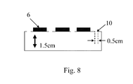
- FIG. 8 is a schematic view of heat dissipation holes provided on the keyboard according to the embodiment of the present invention.
- FIG. 2 is a schematic view of the heat dissipation device of the notebook computer according to the embodiment of the present invention.
- the heat dissipation device includes a heat dissipation component 21 and a heat guiding box 7
- the heat dissipation component 21 includes a heat guiding pipe 3 , a radiator 4 , and a fan 5
- the heat guiding box 7 is connected between the heat dissipation component 21 and the keyboard 6
- the heat guiding box 7 is capable of transmitting the heat in the heat dissipation component 21 to the keyboard 6 .
- the inner wall of the heat guiding box 7 may be coated with a heat insulating material, so as to reduce the loss of heat during the transmitting process.
- One or more heat dissipation holes 10 may be provided on the keyboard 6 .
- Each of the heat dissipation holes 10 may have a circle shape, a rectangular shape, a triangle shape, or other suitable shapes.
- a first control structure 9 which is rotatable and a first valve 13 may be provided in the heat guiding box 7 , so as to control the close and open of the heat transmitting path between the heat dissipation component 21 and the keyboard 6 .
- the first control structure 9 is connected with the first valve 13 to control the first valve 13 .
- the heat transmitting path between the heat dissipation component 21 and the keyboard 6 is closed by the first control structure 9 and the first valve 13 , as shown in FIG. 4 .
- the heat transmitting path between the heat dissipation component 21 and the keyboard 6 is opened by the first control structure 9 and the first valve 13 so that the heat is transmitted to the keyboard 6 , as shown in FIG. 3 .
- the first control structure 9 may be extended out of the notebook computer 20 by about 0.5 cm to 2 cm (for example, 1 cm), so that the first control structure 9 can be rotated manually or electrically.
- the first control structure 9 includes a central shaft 11 and an outer wheel 12 , the central shaft 11 is fixed on the first control structure 9 , and the outer wheel 12 is fitted over the central shaft 11 .
- Fixing elements capable of engaging with each other are provided on the outer wheel 12 and the central shaft 11 , so that the central shaft 11 and the outer wheel 12 are capable of being fixed with each other as shown in FIG. 5 .
- the fixing elements may include a protrusion provided on the central shaft 11 and a groove provided on the outer wheel 12 , and the protrusion and the groove are capable engaging with each other.
- the fixing elements may also include a protrusion provided on the outer wheel 12 and a groove provided on the central shaft 11 , and the protrusion and the groove are capable of engaging with each other.
- the outer wheel 12 may be connected with a slide 15 extending out of the notebook computer 20 .
- the outer wheel 12 is disengaged with the central shaft 11 when the slide 15 slides leftward, as shown in FIG. 6 .
- the central shaft 11 rotates freely for the central shaft 11 and the outer wheel 12 are disengaged with each other, the first valve 13 naturally droops due to the gravity as long as no external forces are applied, and thereby the heat transmitting path between the heat dissipation component 21 and the keyboard 6 is closed.
- the outer wheel 12 is returned to fit over the central shaft 11 due to the push of the spring 14 , and is engaged with the central shaft 11 again.
- the first control structure 9 may also be rotated manually so that the first valve 13 is opened with different angles (for example, 0 degree, 30 degrees, 60 degrees, 90 degrees and so on), as shown in FIG. 7 . Thereafter, the slide 15 is released, the outer wheel 12 is returned to fit over the central shaft 11 due to the push of the spring 14 , and is engaged with the central shaft 11 again.
- the opening of the heat transmitting path between the heat dissipation component 21 and the keyboard 6 can have different sizes are, and thereby the amount of the heat provided for the keyboard 6 can be controlled.
- the heat dissipation component 21 may also be provided with a second control structure 8 between the radiator 4 and the fan 5 , so as to control the close or open of the heat transmitting path between the radiator 4 and the fan 5 .
- the second control structure 8 and a second valve connected to the second control structure 8 are controlled to close the heat transmitting path between the radiator 4 and the fan 5 , so that the heat dissipation by the fan 5 is reduced and the heat is provided to the keyboard 6 as much as possible.
- the second control structure 8 and the second valve connected to the second control structure 8 are controlled to open the heat transmitting path between the radiator 4 and the fan 5 , so that the heat is dissipated by the fan 5 as much as possible without the necessary to provide the heat to the keyboard 6 .
- the configuration and operation principle of the second control structure 8 are same to those of the first control structure 9 , and thus their detail descriptions are omitted here for simplicity.
- each heat dissipation hole 10 may be 0.5 cm, as shown in FIG. 8 .
- a filter may be further provided on each heat dissipation hole 10 , so as to prevent the dust from entering.
- the height of the chamber of the keyboard 6 may be set as 1.5 cm.
- the heat dissipation device changes the heat dissipation manner of the conventional notebook computer, and is capable of guiding the heat generated by the graphics card and the CPU to the keyboard, so that the heat generated in the notebook computer can be recycled effectively instead of being discharged directly and the waste of the heat energy can be avoided. Furthermore, the heat dissipation device according to the embodiments of the present invention is capable of taking full advantage of the heat generated by the notebook computer while increasing the heat dissipation, so that the case in which the hands of the on-site worker using the notebook computer outdoors are prone to be frozen stiff or even be frostbit can be avoided.
Landscapes
- Engineering & Computer Science (AREA)
- Theoretical Computer Science (AREA)
- Computer Hardware Design (AREA)
- Human Computer Interaction (AREA)
- Physics & Mathematics (AREA)
- General Engineering & Computer Science (AREA)
- General Physics & Mathematics (AREA)
- Cooling Or The Like Of Electrical Apparatus (AREA)
- Cookers (AREA)
- Temperature-Responsive Valves (AREA)
Applications Claiming Priority (3)
| Application Number | Priority Date | Filing Date | Title |
|---|---|---|---|
| CN201210314166 | 2012-08-29 | ||
| CN201210314166.1 | 2012-08-29 | ||
| CN201210314166.1A CN103677167B (zh) | 2012-08-29 | 2012-08-29 | 一种散热装置 |
Publications (2)
| Publication Number | Publication Date |
|---|---|
| US20140063713A1 US20140063713A1 (en) | 2014-03-06 |
| US9436237B2 true US9436237B2 (en) | 2016-09-06 |
Family
ID=48985973
Family Applications (1)
| Application Number | Title | Priority Date | Filing Date |
|---|---|---|---|
| US13/959,860 Active US9436237B2 (en) | 2012-08-29 | 2013-08-06 | Heat dissipation device |
Country Status (3)
| Country | Link |
|---|---|
| US (1) | US9436237B2 (fr) |
| EP (1) | EP2703942B1 (fr) |
| CN (1) | CN103677167B (fr) |
Families Citing this family (4)
| Publication number | Priority date | Publication date | Assignee | Title |
|---|---|---|---|---|
| CN106020393A (zh) * | 2016-05-13 | 2016-10-12 | 王翌舟 | 具有发热利用系统的电脑 |
| CN106419098A (zh) * | 2016-11-17 | 2017-02-22 | 麻城英太利济智能物联网科技有限公司 | 一种物联网用电脑机箱散热桌 |
| CN110290080A (zh) * | 2019-06-26 | 2019-09-27 | 彭伶铭 | 一种具有节能辅助装置的通信交换机 |
| CN112286329A (zh) * | 2020-11-26 | 2021-01-29 | 南京微智新科技有限公司 | 笔记本电脑及其散热模组 |
Citations (8)
| Publication number | Priority date | Publication date | Assignee | Title |
|---|---|---|---|---|
| US5329829A (en) * | 1993-01-22 | 1994-07-19 | Ingersoll-Rand Company | Indicating positive positioning selector knob lock |
| US20030218862A1 (en) * | 2002-05-24 | 2003-11-27 | International Business Machines Corporation | Temperature-controlled user interface |
| US20070177350A1 (en) * | 2006-01-31 | 2007-08-02 | Kabushiki Kaisha Toshiba | Electronic device |
| US7701709B2 (en) * | 2006-05-23 | 2010-04-20 | Kabushiki Kaisha Toshiba | Electronic apparatus |
| US20110075352A1 (en) * | 2008-06-12 | 2011-03-31 | Trentent Tye | Electronic Device With Deployable Air Flow Enhancing Support |
| US20110103005A1 (en) * | 2009-10-31 | 2011-05-05 | Hewlett-Packard Development Company Lp | Airflow restrictor door |
| CN102480905A (zh) | 2010-11-24 | 2012-05-30 | 英业达股份有限公司 | 散热装置 |
| CN202275351U (zh) | 2011-09-22 | 2012-06-13 | 无锡艾德里安科技有限公司 | 一种笔记本加散热装置 |
-
2012
- 2012-08-29 CN CN201210314166.1A patent/CN103677167B/zh active Active
-
2013
- 2013-08-06 US US13/959,860 patent/US9436237B2/en active Active
- 2013-08-09 EP EP13179838.1A patent/EP2703942B1/fr active Active
Patent Citations (8)
| Publication number | Priority date | Publication date | Assignee | Title |
|---|---|---|---|---|
| US5329829A (en) * | 1993-01-22 | 1994-07-19 | Ingersoll-Rand Company | Indicating positive positioning selector knob lock |
| US20030218862A1 (en) * | 2002-05-24 | 2003-11-27 | International Business Machines Corporation | Temperature-controlled user interface |
| US20070177350A1 (en) * | 2006-01-31 | 2007-08-02 | Kabushiki Kaisha Toshiba | Electronic device |
| US7701709B2 (en) * | 2006-05-23 | 2010-04-20 | Kabushiki Kaisha Toshiba | Electronic apparatus |
| US20110075352A1 (en) * | 2008-06-12 | 2011-03-31 | Trentent Tye | Electronic Device With Deployable Air Flow Enhancing Support |
| US20110103005A1 (en) * | 2009-10-31 | 2011-05-05 | Hewlett-Packard Development Company Lp | Airflow restrictor door |
| CN102480905A (zh) | 2010-11-24 | 2012-05-30 | 英业达股份有限公司 | 散热装置 |
| CN202275351U (zh) | 2011-09-22 | 2012-06-13 | 无锡艾德里安科技有限公司 | 一种笔记本加散热装置 |
Non-Patent Citations (3)
| Title |
|---|
| European Patent Office Communication Appln. No. 13 179 838.1-1959; Dated Sep. 24, 2015. |
| Extended European Search Report dated Aug. 27, 2014; Appln. No. 13179838.1-1959/2703942. |
| First Chinese Office Action dated Apr. 5, 2016; Appln. No. 201210314166.1. |
Also Published As
| Publication number | Publication date |
|---|---|
| EP2703942A2 (fr) | 2014-03-05 |
| US20140063713A1 (en) | 2014-03-06 |
| CN103677167A (zh) | 2014-03-26 |
| EP2703942A3 (fr) | 2014-09-24 |
| EP2703942B1 (fr) | 2017-10-25 |
| CN103677167B (zh) | 2017-10-13 |
Similar Documents
| Publication | Publication Date | Title |
|---|---|---|
| US9436237B2 (en) | Heat dissipation device | |
| CN204489596U (zh) | 一种便携式温控试剂箱 | |
| US8120910B2 (en) | Heat dissipating structure | |
| US20150062805A1 (en) | Electronic device | |
| BR112017012582A2 (pt) | sistema de controle de acesso integrado, métodos para administrar em modo sem fios um ponto de acesso, para garantir um ponto de acesso, para administrar um evento de entrada de ponto de acesso e para capturar um evento de violação a um ponto de acesso, e, dispositivo hospedeiro. | |
| US9410557B2 (en) | Cooling fan with variable blade surface area | |
| WO2011123480A3 (fr) | Affichage accessible dans un dispositif avec couvercle fermé | |
| US9152190B2 (en) | Collapsible chimney for electronic device | |
| JP2013048223A5 (fr) | ||
| EP2706430A2 (fr) | Ordinateur portable disposant d'une structure de dissipation thermique | |
| US9936609B2 (en) | Mobile terminal heat dissipation mechanism and terminal having same | |
| US20140118944A1 (en) | Electronic device | |
| US9771951B2 (en) | Composite cooling fan | |
| WO2008067489A3 (fr) | Mécanisme de verrouillage pour module | |
| CN203761746U (zh) | 一种监控相机的散热结构 | |
| CN106766586A (zh) | 左右开门机构及冰箱 | |
| CN205059444U (zh) | 一种手套箱的旋转式风口开关、手套箱及车辆 | |
| US20130137357A1 (en) | Container data center and method for controlling airflow into the container data center | |
| US9513674B2 (en) | Rotary flap door device and electronic device therewith | |
| CN205193688U (zh) | 应用于笔记本电脑的连杆机构以及笔记本电脑 | |
| CN205677876U (zh) | 一种防止电动机冷却风扇罩壳堵塞的装置 | |
| CN205652378U (zh) | 一种用于多旋翼无人机的保护罩 | |
| CN105007705B (zh) | 针对电子装置中的电子元件的散热系统与散热方法 | |
| US20120147543A1 (en) | Modular data center | |
| US20170310146A1 (en) | Wireless Charging Device and Notebook Computer |
Legal Events
| Date | Code | Title | Description |
|---|---|---|---|
| AS | Assignment |
Owner name: BEIJING BOE OPTOELECTRONICS TECHNOLOGY CO., LTD., Free format text: ASSIGNMENT OF ASSIGNORS INTEREST;ASSIGNORS:SONG, YONG;LIU, JUNGUO;REEL/FRAME:030947/0434 Effective date: 20130708 |
|
| STCF | Information on status: patent grant |
Free format text: PATENTED CASE |
|
| MAFP | Maintenance fee payment |
Free format text: PAYMENT OF MAINTENANCE FEE, 4TH YEAR, LARGE ENTITY (ORIGINAL EVENT CODE: M1551); ENTITY STATUS OF PATENT OWNER: LARGE ENTITY Year of fee payment: 4 |
|
| MAFP | Maintenance fee payment |
Free format text: PAYMENT OF MAINTENANCE FEE, 8TH YEAR, LARGE ENTITY (ORIGINAL EVENT CODE: M1552); ENTITY STATUS OF PATENT OWNER: LARGE ENTITY Year of fee payment: 8 |