US9447865B2 - Transmission operating mechanism - Google Patents
Transmission operating mechanism Download PDFInfo
- Publication number
- US9447865B2 US9447865B2 US14/394,609 US201314394609A US9447865B2 US 9447865 B2 US9447865 B2 US 9447865B2 US 201314394609 A US201314394609 A US 201314394609A US 9447865 B2 US9447865 B2 US 9447865B2
- Authority
- US
- United States
- Prior art keywords
- shifting
- shaft
- shifting block
- shifting shaft
- operating housing
- Prior art date
- Legal status (The legal status is an assumption and is not a legal conclusion. Google has not performed a legal analysis and makes no representation as to the accuracy of the status listed.)
- Active
Links
Images


Classifications
-
- F—MECHANICAL ENGINEERING; LIGHTING; HEATING; WEAPONS; BLASTING
- F16—ENGINEERING ELEMENTS AND UNITS; GENERAL MEASURES FOR PRODUCING AND MAINTAINING EFFECTIVE FUNCTIONING OF MACHINES OR INSTALLATIONS; THERMAL INSULATION IN GENERAL
- F16H—GEARING
- F16H59/00—Control inputs to control units of change-speed- or reversing-gearings for conveying rotary motion
- F16H59/02—Selector apparatus
-
- F—MECHANICAL ENGINEERING; LIGHTING; HEATING; WEAPONS; BLASTING
- F16—ENGINEERING ELEMENTS AND UNITS; GENERAL MEASURES FOR PRODUCING AND MAINTAINING EFFECTIVE FUNCTIONING OF MACHINES OR INSTALLATIONS; THERMAL INSULATION IN GENERAL
- F16H—GEARING
- F16H61/00—Control functions within control units of change-speed- or reversing-gearings for conveying rotary motion ; Control of exclusively fluid gearing, friction gearing, gearings with endless flexible members or other particular types of gearing
- F16H61/26—Generation or transmission of movements for final actuating mechanisms
- F16H61/28—Generation or transmission of movements for final actuating mechanisms with at least one movement of the final actuating mechanism being caused by a non-mechanical force, e.g. power-assisted
-
- F—MECHANICAL ENGINEERING; LIGHTING; HEATING; WEAPONS; BLASTING
- F16—ENGINEERING ELEMENTS AND UNITS; GENERAL MEASURES FOR PRODUCING AND MAINTAINING EFFECTIVE FUNCTIONING OF MACHINES OR INSTALLATIONS; THERMAL INSULATION IN GENERAL
- F16H—GEARING
- F16H63/00—Control outputs from the control unit to change-speed- or reversing-gearings for conveying rotary motion or to other devices than the final output mechanism
- F16H63/02—Final output mechanisms therefor; Actuating means for the final output mechanisms
- F16H63/08—Multiple final output mechanisms being moved by a single common final actuating mechanism
- F16H63/20—Multiple final output mechanisms being moved by a single common final actuating mechanism with preselection and subsequent movement of each final output mechanism by movement of the final actuating mechanism in two different ways, e.g. guided by a shift gate
-
- F—MECHANICAL ENGINEERING; LIGHTING; HEATING; WEAPONS; BLASTING
- F16—ENGINEERING ELEMENTS AND UNITS; GENERAL MEASURES FOR PRODUCING AND MAINTAINING EFFECTIVE FUNCTIONING OF MACHINES OR INSTALLATIONS; THERMAL INSULATION IN GENERAL
- F16H—GEARING
- F16H63/00—Control outputs from the control unit to change-speed- or reversing-gearings for conveying rotary motion or to other devices than the final output mechanism
- F16H63/02—Final output mechanisms therefor; Actuating means for the final output mechanisms
- F16H63/30—Constructional features of the final output mechanisms
-
- F—MECHANICAL ENGINEERING; LIGHTING; HEATING; WEAPONS; BLASTING
- F16—ENGINEERING ELEMENTS AND UNITS; GENERAL MEASURES FOR PRODUCING AND MAINTAINING EFFECTIVE FUNCTIONING OF MACHINES OR INSTALLATIONS; THERMAL INSULATION IN GENERAL
- F16H—GEARING
- F16H59/00—Control inputs to control units of change-speed- or reversing-gearings for conveying rotary motion
- F16H59/02—Selector apparatus
- F16H2059/026—Details or special features of the selector casing or lever support
-
- F—MECHANICAL ENGINEERING; LIGHTING; HEATING; WEAPONS; BLASTING
- F16—ENGINEERING ELEMENTS AND UNITS; GENERAL MEASURES FOR PRODUCING AND MAINTAINING EFFECTIVE FUNCTIONING OF MACHINES OR INSTALLATIONS; THERMAL INSULATION IN GENERAL
- F16H—GEARING
- F16H61/00—Control functions within control units of change-speed- or reversing-gearings for conveying rotary motion ; Control of exclusively fluid gearing, friction gearing, gearings with endless flexible members or other particular types of gearing
- F16H61/26—Generation or transmission of movements for final actuating mechanisms
- F16H61/28—Generation or transmission of movements for final actuating mechanisms with at least one movement of the final actuating mechanism being caused by a non-mechanical force, e.g. power-assisted
- F16H61/32—Electric motors , actuators or related electrical control means therefor
- F16H2061/323—Electric motors , actuators or related electrical control means therefor for power assistance, i.e. servos with follow up action
-
- F—MECHANICAL ENGINEERING; LIGHTING; HEATING; WEAPONS; BLASTING
- F16—ENGINEERING ELEMENTS AND UNITS; GENERAL MEASURES FOR PRODUCING AND MAINTAINING EFFECTIVE FUNCTIONING OF MACHINES OR INSTALLATIONS; THERMAL INSULATION IN GENERAL
- F16H—GEARING
- F16H63/00—Control outputs from the control unit to change-speed- or reversing-gearings for conveying rotary motion or to other devices than the final output mechanism
- F16H63/02—Final output mechanisms therefor; Actuating means for the final output mechanisms
- F16H63/30—Constructional features of the final output mechanisms
- F16H2063/3076—Selector shaft assembly, e.g. supporting, assembly or manufacturing of selector or shift shafts; Special details thereof
-
- Y—GENERAL TAGGING OF NEW TECHNOLOGICAL DEVELOPMENTS; GENERAL TAGGING OF CROSS-SECTIONAL TECHNOLOGIES SPANNING OVER SEVERAL SECTIONS OF THE IPC; TECHNICAL SUBJECTS COVERED BY FORMER USPC CROSS-REFERENCE ART COLLECTIONS [XRACs] AND DIGESTS
- Y10—TECHNICAL SUBJECTS COVERED BY FORMER USPC
- Y10T—TECHNICAL SUBJECTS COVERED BY FORMER US CLASSIFICATION
- Y10T74/00—Machine element or mechanism
- Y10T74/20—Control lever and linkage systems
- Y10T74/20012—Multiple controlled elements
- Y10T74/20018—Transmission control
- Y10T74/20177—Particular element [e.g., shift fork, template, etc.]
Definitions
- the present application relates to the technical field of automobile transmissions, and particularly to a transmission operating mechanism.
- gear shifting operating modes in the automobile market, especially in the commercial automobile market, such as single-lever single-H left operation, single-lever single-H right operation, single-lever double-H left operation, single-lever double-H right operation, double-lever single-H left operation, double-lever single-H right operation, double-lever double-H left operation, and double-lever double-H right operation.
- operating modes having a gear shifting booster are widely existed in the market.
- peripheral modified parts are required to match with the transmission, which causes difficulties in storage and manufacture management of peripheral connection parts. Therefore, many enterprises are looking for a reasonable operating mode, which may reduce the modification design, the number of parts, and the costs for production and storage management as much as possible.
- An object of the present application is to provide a transmission operating mechanism to solve the above technical problems.
- a transmission operating mechanism includes an operating housing, wherein an inner shifting shaft is provided in the operating housing, and the operating housing is provided with, from left to right, a first position-limiting structure installation hole, a shifting block installation cavity, a second position-limiting structure installation hole and a balancing spring installation cavity; and a shifting block is installed in the shifting block installation cavity and is connected to the inner shifting shaft via a shifting block positioning pin.
- the inner shifting shaft protrudes out of a left end of the operating housing to be fixedly connected to the outer shifting arm, and a sealing member for sealing the spring installation cavity is installed at a right end of the operating housing; or the inner shifting shaft protrudes out of a right end of the operating housing to be fixedly connected to the outer shifting arm, and a sealing member is installed at a left end of the operating housing.
- a booster installation cavity located in the operating housing is provided at a left side of the first position-limiting structure installation hole; an outer shifting shaft is sleeved on the inner shifting shaft; a booster outer-shaft shifting block and a booster inner-shaft shifting block are installed in the booster installation cavity; the booster inner-shaft shifting block is connected to the inner shifting shaft via a pin shaft; the booster outer-shaft shifting block is fixedly connected to the outer shifting shaft; and the shifting block is connected to the outer shifting shaft and the inner shifting shaft via the positioning pin, and an interlocking block is sleeved on the outer shifting shaft.
- the shifting shaft is provided with a first position-limiting protruding portion
- a first pin is installed in each of the first position-limiting structure installation holes at an upper end and a lower end of the operating housing, and is retained in each of the first position-limiting structure installation holes via a first spring and a first thread plug, and a front end of the first pin cooperates with the first position-limiting protruding portion of the inner shifting shaft.
- the inner shifting shaft is provided with a second position-limiting protruding portion
- a second pin is installed in the second position-limiting structure installation hole of the operating housing, and is retained in the second position-limiting structure installation hole via a second spring and a second bolt, and a front end of the second pin cooperates with the second position-limiting protruding portion of the inner shifting shaft.
- a balancing spring configured to cooperate with the inner shifting shaft is installed in the balancing spring installation cavity.
- an outer wall of the outer shifting shaft is provided with a groove
- a position-limiting steel ball roller is installed in the operating housing via a third spring and a third thread plug and is protruding into the groove in the outer wall of the outer shifting shaft.
- the present application has the following advantages.
- the spatial position of the operating housing is fully utilized to effectively arrange each functional component, and the requirement for modification is fully considered within the limited dimensional range, therefore, various operation modes may be achieved by simply providing several modified parts without changing the operating housing.
- Such structure may be used in various operation modes, such as single-lever operation, double-lever operation, single-H operation, double-H operation, left operation, right operation, operation with a booster or without a booster, and any combination thereof, therefore, the number of the modified parts is effectively reduced, which reduces costs for manufacture and storage, and avoids the mis-installation phenomenon caused by excessive peripheral parts.
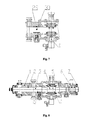
- FIG. 1 is a schematic view showing the structure of an embodiment of the present application
- FIG. 2 is a sectional view of a shifting block in FIG. 1 ;
- FIG. 3 is a partial view of the shifting block in FIG. 1 ;
- FIG. 4 is partial view of a right end of FIG. 1 ;
- FIG. 5 is a partial view of a positioning ball roller in FIG. 1 ;
- FIG. 6 is a partial view of a left end of FIG. 1 ;
- FIG. 7 is a schematic view showing the structure of another embodiment of the present application.
- FIG. 8 is a schematic view showing the structure of another embodiment of the present application.
- FIG. 9 is a sectional view taken along line Y 5 -Y 5 in FIG. 1 ;
- FIG. 10 is a schematic view showing the structure of another embodiment with a booster according to the present application.
- FIG. 11 is a schematic view showing the structure of another embodiment without the booster shown in FIG. 10 according to the present application.
- FIG. 12 is a schematic view showing the structure of the present application with an outer shifting arm being located at the right side;
- FIG. 13 is a schematic view showing the cooperation between the shifting block and an air valve under a double-H operation mode.
- a transmission operating mechanism includes an operating housing 1 , an outer shifting shaft 2 , an inner shifting shaft 3 , a shifting block 4 , an interlocking block 5 , a balancing spring 6 , an end cap 7 , an operating window cover 8 , a gear-selecting shifting block 9 , a gear-selecting shaft 10 , an air valve 11 , a shifting block positioning pin 13 , a positioning steel ball roller 14 , a booster outer-shaft shifting block 22 , a booster inner-shaft shifting block 23 , a pin shaft 24 and an outer shifting arm 28 .
- the outer shifting arm 28 is connected to the inner shifting shaft 3 by splines or in a fixed connection.
- the booster inner-shaft shifting block 23 is connected to the inner shifting shaft 3 via a pin shaft 24 .
- the booster outer-shaft shifting block 22 and the outer shifting shaft 2 are connected in a fixed connection, or are fixed by other connection manners, such as pin connection.
- the shifting block 4 and the interlocking block 5 are sleeved on the outer shifting shaft 2 , the shifting block 4 is connected to the outer shifting shaft 2 and inner shifting shaft 3 via the shifting block positioning pin 13 , and a small clearance is provided between the shifting block positioning pin 13 and a connecting hole in the inner shifting shaft 3 for connecting the shifting block positioning pin 13 .
- the operating housing 1 is provided with a booster installation cavity 500 , a first position-limiting structure installation hole 100 , a shifting block installation cavity 200 , a second position-limiting structure installation hole 300 and a balancing spring installation cavity 400 sequentially from left to right.
- FIG. 1 A solution of a single-H left operation with a booster is shown in FIG. 1 , which may be employed in single-lever operation or double-lever operation.
- the outer shifting arm 28 drives the inner shifting shaft 3 and the shifting block 4 to move rightward or leftward to select a gear position, and the outer shifting arm 28 drives the inner shifting shaft 3 to rotate to shift gear.
- the gear-selecting shaft 10 rotates to drive the gear-selecting shifting block 9 to rotate, which further drives the shifting block 4 and the inner shifting shaft 3 to move rightward or leftward to select a gear position, and the outer shifting arm 28 drives the inner shifting shaft 3 to rotate to shift gear.
- the outer shifting arm 28 rotates together with the inner shifting shaft 3
- the inner shifting shaft 3 drives the booster inner-shaft shifting block 23 to rotate via the pin shaft 24
- a valve of the booster is opened by the rotation of the booster inner-shaft shifting block
- a cylinder piston of the booster pushes the booster outer-shaft shifting block 22 to rotate.
- the booster outer-shaft shifting block 22 is fixedly connected to the outer shifting shaft 2
- the outer shifting shaft 2 is driven to rotate, which further drives the shifting block 4 to rotate via the shifting block positioning pin 13 provided in a hole or a groove of the outer shifting shaft 2 , and a guiding block in the transmission is pushed by the shifting block 4 to move, thereby finishing the gear shifting operation.
- the interlocking block 5 does not rotate, and the relative position between the interlocking block 5 and the shifting block 4 is fixed, only the guiding block corresponding to the shifting block 4 is allowed to be pushed, and other guiding blocks are not allowed to move, which avoids the possibility of two gears are engaged simultaneously.
- the inner shifting shaft 3 is provided with a second position-limiting protruding portion, and a second pin 19 is installed in the second position-limiting structure installation hole of the operating housing 1 , and is retained in the second position-limiting structure installation hole via a second spring 20 and a second bolt 21 , and a front end of the second pin 19 cooperates with the second position-limiting protruding portion of the inner shifting shaft 3 .
- the inner shifting shaft 3 is machined to form a first position-limiting protruding portion, and two position-limiting structures, each including a first spring 26 , a first pin 27 and a first thread plug 25 , are provided at an upper end and a lower end of the operating housing 1 respectively, thereby realizing the double-H operation.
- the first pin 27 is installed in the first position-limiting structure installation hole of the operating housing 1 , and is retained at this position via the first spring 26 and the first thread plug 25 , and a front end of the first pin 27 cooperates with the first position-limiting protruding portion of the inner shifting shaft 3 .
- the double-H operation has two neutral gear positions (a first neutral gear position is shown in the figure).
- the second neutral gear position When the operating lever is in the first neutral gear position, the second neutral gear position may be reached by moving the operating lever rightwards, and at this time, the first pin 27 will be limited at the left side of the position-limiting protruding portion of the inner shifting shaft 3 , and the pressing down and springing up of the first pin 27 may provide a haptic feedback to the driver.
- the haptic feedback of shifting from the second neutral gear position to the first neutral gear position is provided in the same way as the above manner.
- the shifting block 4 sleeved on the inner shifting shaft 3 may squeeze or release the air valve 11 , the air valve 11 controls an auxiliary transmission cylinder to shift the auxiliary transmission to a high-gear position or a low-gear position, and then the inner shifting shaft 3 is rotated, and the shifting block 4 shifts the shifting fork shaft to engage in one of the two gear positions which are respectively located two sides of the second neutral gear position.
- the shifting block 4 is provided with two steps, and the two steps are connected by a slope, and the two steps correspond to two neutral gear positions.
- the two steps cooperate with the air valve 11 to control whether or not to press down the air valve 11 , so as to further shift the auxiliary transmission to a high-gear position or a low-gear position.
- the inner shifting shaft 3 moves rightwards or leftwards to drive the shifting block 4 to move rightwards or leftwards, and the state of the air valve 11 is changed by the two steps of the shifting block 4 , thus, when the operating lever is located in each of the two neutral gear positions, the auxiliary transmission is at the high-gear position or the low-gear position correspondingly. Therefore, the double-H operation is realized.
- An outer wall of the outer shifting shaft 2 is provided with a groove, and a position-limiting steel ball roller 14 is installed in the operating housing 1 via a third spring 15 and a third screw plug 16 and is protruding into the groove in the outer wall of the outer shifting shaft 2 .
- the part indicated by the dashed line in FIG. 6 is omitted, which includes the shifting booster, the booster inner-shaft shifting block 23 , the booster outer-shaft shifting block 22 , the pin shaft 24 , and the outer shifting shaft 2 , and a cover plate is provided to seal the joint surface for the booster, and the part P on the inner shifting shaft 3 for installing the shifting block 4 is thickened or a barrel type spacer bush is provided for fixing the shifting block 4 .
- a structure corresponding to the structure at part F in FIG. 5 is formed in the inner shifting shaft (see part Q in FIG. 8 ), or formed in a sleeve connected to the inner shifting shaft (see parts 29 , 30 in FIG.
- the single-H operation or the double-H operation may both be realized by modifying partial structures of the shifting block 4 and the inner shifting shaft 3 .
- the gear selecting operation of the operation without a booster is the same as that of the operation mode with a booster.
- the outer shifting arm 28 drives the inner shifting shaft 3 to rotate, and the inner shifting shaft 3 drives the shifting block to rotate via the shifting block positioning pin, thereby finishing the gear shifting operation.
- connecting splines of the inner shifting shaft are arranged at the right side of the inner shifting shaft by modifying the structure of the end cap at the right side, and a sealing member 31 is provided to seal an end surface of the operating housing at the left side, and in this way, the right operation modes may be realized, which include right operation with or without a booster, single-H or double-H right operation, and single-lever or double-lever right operation.
- a spring and a steel ball roller are installed at part C to cooperate with part B of the shifting block, to realize a gear position self-locking function of the operating device without a shifting booster.
- a neutral gear detecting device may be installed in a neutral gear detecting device installation hole D, and a reverse gear detecting device may be installed in a reverse gear detecting device installation hole G, thereby monitoring the neutral gear and the reverse gear conditions of the whole automobile.
- a combination of a ball socket and an inclined surface is provided at part F, to provide a haptic feedback of the neutral gear, thus, when the operating mechanism is engaged in a neutral gear position, an obvious haptic feedback may be provided to the driver.
- a ventilation plug and an air valve are respectively disposed at part A and part E, and the ventilation plug is provided to meet the requirement of air pressure balance of the transmission, and the air valve is provided to realize the operating control of the transmission.
Landscapes
- Engineering & Computer Science (AREA)
- General Engineering & Computer Science (AREA)
- Mechanical Engineering (AREA)
- Gear-Shifting Mechanisms (AREA)
Applications Claiming Priority (4)
| Application Number | Priority Date | Filing Date | Title |
|---|---|---|---|
| CN2012204992939U CN202834027U (zh) | 2012-09-27 | 2012-09-27 | 一种变速器操纵机构 |
| CN201220499293.9 | 2012-09-27 | ||
| CN201220499293U | 2012-09-27 | ||
| PCT/CN2013/077761 WO2014048145A1 (zh) | 2012-09-27 | 2013-06-24 | 一种变速器操纵机构 |
Publications (2)
| Publication Number | Publication Date |
|---|---|
| US20150211626A1 US20150211626A1 (en) | 2015-07-30 |
| US9447865B2 true US9447865B2 (en) | 2016-09-20 |
Family
ID=47945736
Family Applications (1)
| Application Number | Title | Priority Date | Filing Date |
|---|---|---|---|
| US14/394,609 Active US9447865B2 (en) | 2012-09-27 | 2013-06-24 | Transmission operating mechanism |
Country Status (5)
| Country | Link |
|---|---|
| US (1) | US9447865B2 (de) |
| EP (1) | EP2902664B1 (de) |
| CN (1) | CN202834027U (de) |
| ES (1) | ES2851574T3 (de) |
| WO (1) | WO2014048145A1 (de) |
Families Citing this family (17)
| Publication number | Priority date | Publication date | Assignee | Title |
|---|---|---|---|---|
| CN202834027U (zh) * | 2012-09-27 | 2013-03-27 | 陕西法士特齿轮有限责任公司 | 一种变速器操纵机构 |
| JP6094459B2 (ja) * | 2013-11-15 | 2017-03-15 | トヨタ自動車株式会社 | 手動変速機 |
| CN103671758A (zh) * | 2013-12-16 | 2014-03-26 | 陕西法士特齿轮有限责任公司 | 一种六档汽车变速器 |
| CN103939594A (zh) * | 2014-03-14 | 2014-07-23 | 陕西法士特齿轮有限责任公司 | 一种带换档助力器变速器的双杆操纵机构 |
| CN103982641A (zh) * | 2014-04-28 | 2014-08-13 | 陕西法士特齿轮有限责任公司 | 一种操纵机构 |
| CN104315137B (zh) * | 2014-11-07 | 2016-10-05 | 西安法士特汽车传动有限公司 | 一种变速器主副箱互锁机构 |
| KR101650634B1 (ko) * | 2014-12-30 | 2016-08-23 | 현대다이모스(주) | 수동 변속기의 셀렉트 조작장치 |
| CN104832634A (zh) * | 2015-05-07 | 2015-08-12 | 陕西法士特齿轮有限责任公司 | 一种单双杆可以相互转化的操纵装置 |
| CN105927731B (zh) * | 2016-06-30 | 2018-03-27 | 陕西法士特齿轮有限责任公司 | 一种变速器双向软轴操纵装置 |
| CN106195239A (zh) * | 2016-08-31 | 2016-12-07 | 陕西法士特齿轮有限责任公司 | 一种变速器操纵机构 |
| CN107420537A (zh) * | 2017-07-31 | 2017-12-01 | 东风商用车有限公司 | 一种内置换挡助力器的变速箱选换挡机构 |
| CN107975592B (zh) * | 2017-12-11 | 2023-08-04 | 陕西法士特齿轮有限责任公司 | 一种变速器双杆操纵装置总成 |
| CN108443481B (zh) * | 2018-03-30 | 2024-08-06 | 宝鸡法士特齿轮有限责任公司 | 一种变速器操纵机构 |
| CN110701294A (zh) * | 2019-09-27 | 2020-01-17 | 西安法士特汽车传动有限公司 | 一种变速器操纵机构总成 |
| CN114776796B (zh) * | 2022-03-22 | 2023-12-08 | 陕西法士特齿轮有限责任公司 | 一种通用倒挡保护锁操纵机构 |
| CN114909455B (zh) * | 2022-05-31 | 2024-10-01 | 东风商用车有限公司 | 变速箱操纵顶盖总成 |
| CN115182992B (zh) * | 2022-06-20 | 2023-11-07 | 陕西法士特齿轮有限责任公司 | 一种调整变速器挂挡助力结构 |
Citations (30)
| Publication number | Priority date | Publication date | Assignee | Title |
|---|---|---|---|---|
| US4275612A (en) * | 1978-03-30 | 1981-06-30 | Eaton Corporation | Shift control for change speed gear transmission for vehicle |
| US4377951A (en) * | 1980-01-09 | 1983-03-29 | Zahnradfabrik Friedrichshafen Ag | Gear-change mechanism for a gear-change transmission consisting of a main drive and a two-range group drive |
| JPS58106257A (ja) | 1981-12-17 | 1983-06-24 | Isuzu Motors Ltd | 歯車変速機の変速操作機構 |
| US4455883A (en) * | 1980-11-14 | 1984-06-26 | Eaton Corporation | Combined shift control |
| US4476739A (en) * | 1981-09-04 | 1984-10-16 | Toyota Jidosha Kabushiki Kaisha | Gear-shift mechanism for power transmission units |
| US4539859A (en) * | 1981-10-20 | 1985-09-10 | Toyota Jidosha Kabushiki Kaisha | Shift mechanism in a manual transmission |
| US4569247A (en) * | 1982-12-15 | 1986-02-11 | Toyota Jidosha Kabushiki Kaisha | Detent mechanism in manual transmission |
| US4944197A (en) * | 1989-06-07 | 1990-07-31 | Eaton Corporation | Resilient range interlock |
| US4974468A (en) * | 1989-02-16 | 1990-12-04 | Eaton Corporation | Compound transmission and shift control therefor |
| US5000060A (en) * | 1989-02-16 | 1991-03-19 | Reynolds Joseph D | Compound transmission and shift control therefor |
| US5183132A (en) * | 1989-11-10 | 1993-02-02 | Mitsubishi Jidosha Kogyo Kabushiki Kaisha | Power transfer device having center differential gear for four-wheel drive vehicle |
| US5850760A (en) * | 1995-12-29 | 1998-12-22 | Kia Heavy Industries Corporation | Booster for transmission gear boxes |
| US5852952A (en) * | 1996-03-29 | 1998-12-29 | Nissan Diesel Motor Co., Ltd. | Buffer device for transmission operating booster |
| US6000294A (en) * | 1997-11-15 | 1999-12-14 | Eaton Corporation | System and method for fluid assisted shifting of mechanical transmissions |
| US6165103A (en) * | 1999-05-07 | 2000-12-26 | Visteon Global Technologies, Inc. | Shifting mechanism |
| US6257084B1 (en) * | 1997-11-21 | 2001-07-10 | Kanzaki Kokyukoki Mfg. Co., Ltd. | Transmission |
| US6722218B1 (en) * | 1998-09-02 | 2004-04-20 | Zf Friedrichshafen Ag | Shifting device for a variable speed vehicle transmission |
| US6732607B2 (en) * | 2001-09-28 | 2004-05-11 | Isuzu Motors Limited | Gear change device |
| US20040099079A1 (en) * | 2000-09-09 | 2004-05-27 | Gerhard Fuhrer | Manually operated gear box for commercial vehicles |
| EP1450073A2 (de) | 2003-02-21 | 2004-08-25 | Calsonic Kansei Corporation | Schalthebel eines Getriebes eines Fahrzeugs |
| US6792821B1 (en) * | 2001-08-21 | 2004-09-21 | Isuzu Motors Limited | Shifting device for a transmission |
| US6810762B2 (en) * | 2001-06-18 | 2004-11-02 | Isuzu Motors Limited | Gear change device |
| US6892601B2 (en) * | 2001-06-29 | 2005-05-17 | Isuzu Motors Limited | Gear change device |
| US7104150B2 (en) * | 2003-04-24 | 2006-09-12 | Honda Motor Co., Ltd. | Shift position detection apparatus for variable speed gear |
| CN2842101Y (zh) | 2005-11-11 | 2006-11-29 | 韶关宏大齿轮有限公司 | 汽车变速器气动换档装置 |
| US20100011898A1 (en) * | 2006-12-13 | 2010-01-21 | Zf Friedrichshafen Ag | Shifting device for a manual transmission of a vehicle |
| CN101936390A (zh) | 2010-07-31 | 2011-01-05 | 浙江万里扬变速器股份有限公司 | 汽车变速器顶盖总成 |
| CN102494120A (zh) | 2011-12-26 | 2012-06-13 | 中国重汽集团济南动力有限公司 | 一种新型变速器选换挡机构总成 |
| CN202834027U (zh) | 2012-09-27 | 2013-03-27 | 陕西法士特齿轮有限责任公司 | 一种变速器操纵机构 |
| US8578809B2 (en) * | 2007-06-06 | 2013-11-12 | Zf Friedrichshafen Ag | Shifting device for a variable speed motor vehicle transmission |
Family Cites Families (6)
| Publication number | Priority date | Publication date | Assignee | Title |
|---|---|---|---|---|
| DE3929678A1 (de) * | 1989-09-07 | 1991-03-28 | Porsche Ag | Schaltvorrichtung fuer ein zahnraeder-wechselgetriebe eines kraftfahrzeugs |
| DE10032907A1 (de) * | 1999-07-14 | 2001-02-01 | Luk Lamellen & Kupplungsbau | Getriebevorrichtung mit Schalteinrichtung |
| DE10217908A1 (de) * | 2002-04-23 | 2003-11-06 | Zf Sachs Ag | Stelleinrichtung |
| DE102004041543A1 (de) * | 2004-08-27 | 2006-03-02 | Zf Friedrichshafen Ag | Schaltvorrichtung für das Getriebe eines Kraftfahrzeugs |
| DE102006006651A1 (de) * | 2006-02-14 | 2007-08-16 | Zf Friedrichshafen Ag | Schaltvorrichtung für Kraftfahrzeug-Wechselgetriebe |
| DE102008029265B4 (de) * | 2008-06-19 | 2022-03-24 | Schaeffler Technologies AG & Co. KG | Schaltfingeranordnung und Verfahren zu ihrer Herstellung sowie Schaltmecha-nismus mit der Schaltfingeranordnung |
-
2012
- 2012-09-27 CN CN2012204992939U patent/CN202834027U/zh not_active Expired - Lifetime
-
2013
- 2013-06-24 WO PCT/CN2013/077761 patent/WO2014048145A1/zh not_active Ceased
- 2013-06-24 ES ES13841771T patent/ES2851574T3/es active Active
- 2013-06-24 EP EP13841771.2A patent/EP2902664B1/de active Active
- 2013-06-24 US US14/394,609 patent/US9447865B2/en active Active
Patent Citations (30)
| Publication number | Priority date | Publication date | Assignee | Title |
|---|---|---|---|---|
| US4275612A (en) * | 1978-03-30 | 1981-06-30 | Eaton Corporation | Shift control for change speed gear transmission for vehicle |
| US4377951A (en) * | 1980-01-09 | 1983-03-29 | Zahnradfabrik Friedrichshafen Ag | Gear-change mechanism for a gear-change transmission consisting of a main drive and a two-range group drive |
| US4455883A (en) * | 1980-11-14 | 1984-06-26 | Eaton Corporation | Combined shift control |
| US4476739A (en) * | 1981-09-04 | 1984-10-16 | Toyota Jidosha Kabushiki Kaisha | Gear-shift mechanism for power transmission units |
| US4539859A (en) * | 1981-10-20 | 1985-09-10 | Toyota Jidosha Kabushiki Kaisha | Shift mechanism in a manual transmission |
| JPS58106257A (ja) | 1981-12-17 | 1983-06-24 | Isuzu Motors Ltd | 歯車変速機の変速操作機構 |
| US4569247A (en) * | 1982-12-15 | 1986-02-11 | Toyota Jidosha Kabushiki Kaisha | Detent mechanism in manual transmission |
| US4974468A (en) * | 1989-02-16 | 1990-12-04 | Eaton Corporation | Compound transmission and shift control therefor |
| US5000060A (en) * | 1989-02-16 | 1991-03-19 | Reynolds Joseph D | Compound transmission and shift control therefor |
| US4944197A (en) * | 1989-06-07 | 1990-07-31 | Eaton Corporation | Resilient range interlock |
| US5183132A (en) * | 1989-11-10 | 1993-02-02 | Mitsubishi Jidosha Kogyo Kabushiki Kaisha | Power transfer device having center differential gear for four-wheel drive vehicle |
| US5850760A (en) * | 1995-12-29 | 1998-12-22 | Kia Heavy Industries Corporation | Booster for transmission gear boxes |
| US5852952A (en) * | 1996-03-29 | 1998-12-29 | Nissan Diesel Motor Co., Ltd. | Buffer device for transmission operating booster |
| US6000294A (en) * | 1997-11-15 | 1999-12-14 | Eaton Corporation | System and method for fluid assisted shifting of mechanical transmissions |
| US6257084B1 (en) * | 1997-11-21 | 2001-07-10 | Kanzaki Kokyukoki Mfg. Co., Ltd. | Transmission |
| US6722218B1 (en) * | 1998-09-02 | 2004-04-20 | Zf Friedrichshafen Ag | Shifting device for a variable speed vehicle transmission |
| US6165103A (en) * | 1999-05-07 | 2000-12-26 | Visteon Global Technologies, Inc. | Shifting mechanism |
| US20040099079A1 (en) * | 2000-09-09 | 2004-05-27 | Gerhard Fuhrer | Manually operated gear box for commercial vehicles |
| US6810762B2 (en) * | 2001-06-18 | 2004-11-02 | Isuzu Motors Limited | Gear change device |
| US6892601B2 (en) * | 2001-06-29 | 2005-05-17 | Isuzu Motors Limited | Gear change device |
| US6792821B1 (en) * | 2001-08-21 | 2004-09-21 | Isuzu Motors Limited | Shifting device for a transmission |
| US6732607B2 (en) * | 2001-09-28 | 2004-05-11 | Isuzu Motors Limited | Gear change device |
| EP1450073A2 (de) | 2003-02-21 | 2004-08-25 | Calsonic Kansei Corporation | Schalthebel eines Getriebes eines Fahrzeugs |
| US7104150B2 (en) * | 2003-04-24 | 2006-09-12 | Honda Motor Co., Ltd. | Shift position detection apparatus for variable speed gear |
| CN2842101Y (zh) | 2005-11-11 | 2006-11-29 | 韶关宏大齿轮有限公司 | 汽车变速器气动换档装置 |
| US20100011898A1 (en) * | 2006-12-13 | 2010-01-21 | Zf Friedrichshafen Ag | Shifting device for a manual transmission of a vehicle |
| US8578809B2 (en) * | 2007-06-06 | 2013-11-12 | Zf Friedrichshafen Ag | Shifting device for a variable speed motor vehicle transmission |
| CN101936390A (zh) | 2010-07-31 | 2011-01-05 | 浙江万里扬变速器股份有限公司 | 汽车变速器顶盖总成 |
| CN102494120A (zh) | 2011-12-26 | 2012-06-13 | 中国重汽集团济南动力有限公司 | 一种新型变速器选换挡机构总成 |
| CN202834027U (zh) | 2012-09-27 | 2013-03-27 | 陕西法士特齿轮有限责任公司 | 一种变速器操纵机构 |
Also Published As
| Publication number | Publication date |
|---|---|
| US20150211626A1 (en) | 2015-07-30 |
| ES2851574T3 (es) | 2021-09-07 |
| WO2014048145A1 (zh) | 2014-04-03 |
| EP2902664A4 (de) | 2017-07-12 |
| EP2902664A1 (de) | 2015-08-05 |
| EP2902664B1 (de) | 2020-12-16 |
| CN202834027U (zh) | 2013-03-27 |
Similar Documents
| Publication | Publication Date | Title |
|---|---|---|
| US9447865B2 (en) | Transmission operating mechanism | |
| JP6810809B2 (ja) | 変速機のシフトレンジ切換アッセンブリー、変速機及び自動車 | |
| EP2740977B1 (de) | Schaltventil | |
| US9188224B2 (en) | Gear shift arrangement with parking block and method for its activation | |
| CN111692327B (zh) | 一种轻型商用车变速器选换挡机构 | |
| CN106641242A (zh) | 一种液压驻车推杆总成、自动变速器和汽车 | |
| CN102748464A (zh) | 一种新型副箱三位置气缸执行机构 | |
| US20090050435A1 (en) | Parking Lock Device for Transmission | |
| CN111692328B (zh) | 一种轻型商用车变速器用选换挡顶盖总成 | |
| US20050178229A1 (en) | Actuation system for a gearbox | |
| CN109931399B (zh) | 一种中轻卡操纵机构总成 | |
| CN115013518A (zh) | 一种手动变速器换挡结构 | |
| JP2015081631A (ja) | 手動変速機のシフト装置 | |
| KR101515008B1 (ko) | 양방향 제어 솔레노이드 밸브 | |
| CN111120542A (zh) | 一种可选择模式的离合器 | |
| CN201457068U (zh) | 一种取力装置的齿轮定位机构 | |
| CN105190125A (zh) | 车辆用停车装置 | |
| CN202946585U (zh) | 一种amt变速器制动装置 | |
| CN209398832U (zh) | 一种集成式手动变速器操纵总成 | |
| CN110701294A (zh) | 一种变速器操纵机构总成 | |
| CN211852568U (zh) | 一种可选择模式的离合器 | |
| KR101348536B1 (ko) | 수동변속기의 컨트롤 어셈블리 | |
| CN115875450A (zh) | 一种电控换挡取力器 | |
| GB2051240A (en) | Fluid Operated Actuating Device | |
| CN105443746A (zh) | 双离合变速器的换挡执行机构 |
Legal Events
| Date | Code | Title | Description |
|---|---|---|---|
| AS | Assignment |
Owner name: SHAANXI FAST GEAR CO., LTD., CHINA Free format text: ASSIGNMENT OF ASSIGNORS INTEREST;ASSIGNORS:ZHANG, FAYONG;LI, LINGLI;YIN, CHONGYI;AND OTHERS;REEL/FRAME:033954/0329 Effective date: 20141010 |
|
| STCF | Information on status: patent grant |
Free format text: PATENTED CASE |
|
| MAFP | Maintenance fee payment |
Free format text: PAYMENT OF MAINTENANCE FEE, 4TH YEAR, LARGE ENTITY (ORIGINAL EVENT CODE: M1551); ENTITY STATUS OF PATENT OWNER: LARGE ENTITY Year of fee payment: 4 |
|
| MAFP | Maintenance fee payment |
Free format text: PAYMENT OF MAINTENANCE FEE, 8TH YEAR, LARGE ENTITY (ORIGINAL EVENT CODE: M1552); ENTITY STATUS OF PATENT OWNER: LARGE ENTITY Year of fee payment: 8 |