US9458709B2 - Heavy oil production with EM preheat and gas injection - Google Patents
Heavy oil production with EM preheat and gas injection Download PDFInfo
- Publication number
- US9458709B2 US9458709B2 US13/729,474 US201213729474A US9458709B2 US 9458709 B2 US9458709 B2 US 9458709B2 US 201213729474 A US201213729474 A US 201213729474A US 9458709 B2 US9458709 B2 US 9458709B2
- Authority
- US
- United States
- Prior art keywords
- gas
- injection
- well
- oil
- wells
- Prior art date
- Legal status (The legal status is an assumption and is not a legal conclusion. Google has not performed a legal analysis and makes no representation as to the accuracy of the status listed.)
- Active, expires
Links
- 238000002347 injection Methods 0.000 title claims abstract description 131
- 239000007924 injection Substances 0.000 title claims abstract description 131
- 239000000295 fuel oil Substances 0.000 title claims abstract description 31
- 238000004519 manufacturing process Methods 0.000 title claims description 83
- 239000003921 oil Substances 0.000 claims abstract description 136
- 238000000034 method Methods 0.000 claims abstract description 90
- 238000011084 recovery Methods 0.000 claims abstract description 56
- 239000012530 fluid Substances 0.000 claims abstract description 28
- 238000004891 communication Methods 0.000 claims abstract description 17
- 230000005855 radiation Effects 0.000 claims abstract description 6
- 239000007789 gas Substances 0.000 claims description 171
- VNWKTOKETHGBQD-UHFFFAOYSA-N methane Chemical compound C VNWKTOKETHGBQD-UHFFFAOYSA-N 0.000 claims description 32
- 230000008569 process Effects 0.000 claims description 32
- 230000005484 gravity Effects 0.000 claims description 23
- ATUOYWHBWRKTHZ-UHFFFAOYSA-N Propane Chemical compound CCC ATUOYWHBWRKTHZ-UHFFFAOYSA-N 0.000 claims description 16
- 230000001976 improved effect Effects 0.000 claims description 13
- OTMSDBZUPAUEDD-UHFFFAOYSA-N Ethane Chemical compound CC OTMSDBZUPAUEDD-UHFFFAOYSA-N 0.000 claims description 8
- 239000001294 propane Substances 0.000 claims description 8
- UGFAIRIUMAVXCW-UHFFFAOYSA-N Carbon monoxide Chemical compound [O+]#[C-] UGFAIRIUMAVXCW-UHFFFAOYSA-N 0.000 claims description 7
- 239000001273 butane Substances 0.000 claims description 7
- 230000005670 electromagnetic radiation Effects 0.000 claims description 7
- 239000003546 flue gas Substances 0.000 claims description 7
- IJDNQMDRQITEOD-UHFFFAOYSA-N n-butane Chemical compound CCCC IJDNQMDRQITEOD-UHFFFAOYSA-N 0.000 claims description 7
- OFBQJSOFQDEBGM-UHFFFAOYSA-N n-pentane Natural products CCCCC OFBQJSOFQDEBGM-UHFFFAOYSA-N 0.000 claims description 7
- 230000006872 improvement Effects 0.000 claims description 6
- 238000010793 Steam injection (oil industry) Methods 0.000 claims description 4
- 230000005540 biological transmission Effects 0.000 claims description 3
- 238000002485 combustion reaction Methods 0.000 claims description 3
- 238000011065 in-situ storage Methods 0.000 claims description 3
- CURLTUGMZLYLDI-UHFFFAOYSA-N Carbon dioxide Chemical compound O=C=O CURLTUGMZLYLDI-UHFFFAOYSA-N 0.000 description 46
- 229910002092 carbon dioxide Inorganic materials 0.000 description 38
- IJGRMHOSHXDMSA-UHFFFAOYSA-N nitrogen Substances N#N IJGRMHOSHXDMSA-UHFFFAOYSA-N 0.000 description 35
- 238000010438 heat treatment Methods 0.000 description 32
- XLYOFNOQVPJJNP-UHFFFAOYSA-N water Substances O XLYOFNOQVPJJNP-UHFFFAOYSA-N 0.000 description 21
- 230000015572 biosynthetic process Effects 0.000 description 16
- 238000005755 formation reaction Methods 0.000 description 16
- 229910052757 nitrogen Inorganic materials 0.000 description 16
- 229930195733 hydrocarbon Natural products 0.000 description 11
- 150000002430 hydrocarbons Chemical class 0.000 description 11
- 239000010426 asphalt Substances 0.000 description 10
- 230000007246 mechanism Effects 0.000 description 9
- 238000010796 Steam-assisted gravity drainage Methods 0.000 description 8
- 239000010779 crude oil Substances 0.000 description 8
- 239000000203 mixture Substances 0.000 description 8
- 238000004088 simulation Methods 0.000 description 8
- 239000004215 Carbon black (E152) Substances 0.000 description 7
- 239000001569 carbon dioxide Substances 0.000 description 7
- 238000006073 displacement reaction Methods 0.000 description 7
- 230000008901 benefit Effects 0.000 description 6
- 239000002904 solvent Substances 0.000 description 6
- XQCFHQBGMWUEMY-ZPUQHVIOSA-N Nitrovin Chemical compound C=1C=C([N+]([O-])=O)OC=1\C=C\C(=NNC(=N)N)\C=C\C1=CC=C([N+]([O-])=O)O1 XQCFHQBGMWUEMY-ZPUQHVIOSA-N 0.000 description 5
- 239000008186 active pharmaceutical agent Substances 0.000 description 4
- 230000007613 environmental effect Effects 0.000 description 4
- 239000007788 liquid Substances 0.000 description 4
- 239000000463 material Substances 0.000 description 4
- 239000003345 natural gas Substances 0.000 description 4
- OKTJSMMVPCPJKN-UHFFFAOYSA-N Carbon Chemical compound [C] OKTJSMMVPCPJKN-UHFFFAOYSA-N 0.000 description 3
- 230000009471 action Effects 0.000 description 3
- 229910052799 carbon Inorganic materials 0.000 description 3
- 230000008859 change Effects 0.000 description 3
- 125000004122 cyclic group Chemical group 0.000 description 3
- 238000002474 experimental method Methods 0.000 description 3
- 238000012423 maintenance Methods 0.000 description 3
- 239000003208 petroleum Substances 0.000 description 3
- 230000008016 vaporization Effects 0.000 description 3
- 238000003491 array Methods 0.000 description 2
- 238000013461 design Methods 0.000 description 2
- 238000011161 development Methods 0.000 description 2
- 230000018109 developmental process Effects 0.000 description 2
- 230000012447 hatching Effects 0.000 description 2
- 239000003915 liquefied petroleum gas Substances 0.000 description 2
- 238000005259 measurement Methods 0.000 description 2
- 230000010534 mechanism of action Effects 0.000 description 2
- JCXJVPUVTGWSNB-UHFFFAOYSA-N nitrogen dioxide Inorganic materials O=[N]=O JCXJVPUVTGWSNB-UHFFFAOYSA-N 0.000 description 2
- 230000009972 noncorrosive effect Effects 0.000 description 2
- 239000000243 solution Substances 0.000 description 2
- 241000196324 Embryophyta Species 0.000 description 1
- 241000237858 Gastropoda Species 0.000 description 1
- 241000184339 Nemophila maculata Species 0.000 description 1
- 238000010521 absorption reaction Methods 0.000 description 1
- 230000004075 alteration Effects 0.000 description 1
- 238000013459 approach Methods 0.000 description 1
- 230000033228 biological regulation Effects 0.000 description 1
- 239000006227 byproduct Substances 0.000 description 1
- 230000005465 channeling Effects 0.000 description 1
- 239000011248 coating agent Substances 0.000 description 1
- 238000000576 coating method Methods 0.000 description 1
- 239000004020 conductor Substances 0.000 description 1
- 230000001351 cycling effect Effects 0.000 description 1
- 230000007423 decrease Effects 0.000 description 1
- 230000001419 dependent effect Effects 0.000 description 1
- 229910001873 dinitrogen Inorganic materials 0.000 description 1
- 238000005553 drilling Methods 0.000 description 1
- 230000005684 electric field Effects 0.000 description 1
- 230000002349 favourable effect Effects 0.000 description 1
- 230000006870 function Effects 0.000 description 1
- 230000001939 inductive effect Effects 0.000 description 1
- 239000011261 inert gas Substances 0.000 description 1
- 230000001483 mobilizing effect Effects 0.000 description 1
- 108010024605 neurotensin mimic 2 Proteins 0.000 description 1
- QJGQUHMNIGDVPM-UHFFFAOYSA-N nitrogen(.) Chemical compound [N] QJGQUHMNIGDVPM-UHFFFAOYSA-N 0.000 description 1
- 239000003027 oil sand Substances 0.000 description 1
- 238000005457 optimization Methods 0.000 description 1
- 230000035515 penetration Effects 0.000 description 1
- 239000011148 porous material Substances 0.000 description 1
- 230000009467 reduction Effects 0.000 description 1
- 238000011160 research Methods 0.000 description 1
- 238000005204 segregation Methods 0.000 description 1
- 238000000926 separation method Methods 0.000 description 1
- 230000009919 sequestration Effects 0.000 description 1
- 239000003079 shale oil Substances 0.000 description 1
- 238000001179 sorption measurement Methods 0.000 description 1
- 238000006467 substitution reaction Methods 0.000 description 1
- 230000008961 swelling Effects 0.000 description 1
- 238000012546 transfer Methods 0.000 description 1
- 238000009834 vaporization Methods 0.000 description 1
Images




Classifications
-
- E—FIXED CONSTRUCTIONS
- E21—EARTH OR ROCK DRILLING; MINING
- E21B—EARTH OR ROCK DRILLING; OBTAINING OIL, GAS, WATER, SOLUBLE OR MELTABLE MATERIALS OR A SLURRY OF MINERALS FROM WELLS
- E21B43/00—Methods or apparatus for obtaining oil, gas, water, soluble or meltable materials or a slurry of minerals from wells
- E21B43/16—Enhanced recovery methods for obtaining hydrocarbons
- E21B43/24—Enhanced recovery methods for obtaining hydrocarbons using heat, e.g. steam injection
- E21B43/2401—Enhanced recovery methods for obtaining hydrocarbons using heat, e.g. steam injection by means of electricity
-
- E—FIXED CONSTRUCTIONS
- E21—EARTH OR ROCK DRILLING; MINING
- E21B—EARTH OR ROCK DRILLING; OBTAINING OIL, GAS, WATER, SOLUBLE OR MELTABLE MATERIALS OR A SLURRY OF MINERALS FROM WELLS
- E21B43/00—Methods or apparatus for obtaining oil, gas, water, soluble or meltable materials or a slurry of minerals from wells
- E21B43/16—Enhanced recovery methods for obtaining hydrocarbons
- E21B43/164—Injecting CO2 or carbonated water
-
- E—FIXED CONSTRUCTIONS
- E21—EARTH OR ROCK DRILLING; MINING
- E21B—EARTH OR ROCK DRILLING; OBTAINING OIL, GAS, WATER, SOLUBLE OR MELTABLE MATERIALS OR A SLURRY OF MINERALS FROM WELLS
- E21B43/00—Methods or apparatus for obtaining oil, gas, water, soluble or meltable materials or a slurry of minerals from wells
- E21B43/16—Enhanced recovery methods for obtaining hydrocarbons
- E21B43/166—Injecting a gaseous medium; Injecting a gaseous medium and a liquid medium
- E21B43/168—Injecting a gaseous medium
-
- E—FIXED CONSTRUCTIONS
- E21—EARTH OR ROCK DRILLING; MINING
- E21B—EARTH OR ROCK DRILLING; OBTAINING OIL, GAS, WATER, SOLUBLE OR MELTABLE MATERIALS OR A SLURRY OF MINERALS FROM WELLS
- E21B43/00—Methods or apparatus for obtaining oil, gas, water, soluble or meltable materials or a slurry of minerals from wells
- E21B43/16—Enhanced recovery methods for obtaining hydrocarbons
- E21B43/24—Enhanced recovery methods for obtaining hydrocarbons using heat, e.g. steam injection
- E21B43/2403—Enhanced recovery methods for obtaining hydrocarbons using heat, e.g. steam injection by means of nuclear energy
-
- Y—GENERAL TAGGING OF NEW TECHNOLOGICAL DEVELOPMENTS; GENERAL TAGGING OF CROSS-SECTIONAL TECHNOLOGIES SPANNING OVER SEVERAL SECTIONS OF THE IPC; TECHNICAL SUBJECTS COVERED BY FORMER USPC CROSS-REFERENCE ART COLLECTIONS [XRACs] AND DIGESTS
- Y02—TECHNOLOGIES OR APPLICATIONS FOR MITIGATION OR ADAPTATION AGAINST CLIMATE CHANGE
- Y02P—CLIMATE CHANGE MITIGATION TECHNOLOGIES IN THE PRODUCTION OR PROCESSING OF GOODS
- Y02P90/00—Enabling technologies with a potential contribution to greenhouse gas [GHG] emissions mitigation
- Y02P90/70—Combining sequestration of CO2 and exploitation of hydrocarbons by injecting CO2 or carbonated water in oil wells
Definitions
- This invention relates to methods of enhanced oil recovery that combines gas drive mechanisms with RF mobilization of hydrocarbon deposits.
- Heavy crude oil or extra heavy crude oil is any type of crude oil that does not flow easily. It is referred to as “heavy” because its density or specific gravity is higher than that of light crude oil. Heavy crude oil has been defined as any liquid petroleum with an API gravity less than 20°. Extra heavy oil is defined with API gravity below 10.0° API (i.e. with density greater than 1000 kg/m 3 or, equivalently, a specific gravity greater than 1).
- miscible gas injection the gas is injected at or above minimum miscibility pressure (MMP), which causes the gas to be miscible in the oil, thus thinning it.
- immiscible gas injection by contrast, flooding by the gas is conducted below MMP. This low pressure injection of gas is used to maintain reservoir pressure to prevent production cut-off and thereby increase the rate of production.
- Gas or other fluid can be injected into the formation merely to maintain the pressure drive.
- This traditional step for increasing oil recovery involves the injection of fluid into (or near) an oil reservoir for the purpose of delaying the pressure decline during oil production.
- Pressure maintenance can significantly increase the amount of economically recoverable oil over that to be expected with no pressure maintenance.
- High pressure miscible injection processes can be broken down into the following techniques:
- Displacement by miscible slug usually refers to the injection of some liquid solvent that is miscible upon first contact with the resident crude oil.
- this process uses a slug of propane or other liquefied petroleum gas (2 to 5% pore volume or “PV”) tailed by natural gas, inert gas, and/or water.
- PV pore volume
- a slug of methane enriched with ethane, propane, or butane (10 to 20% PV) and tailed by lean gas and/or water is injected into the reservoir.
- the enriching components are slaked from the injected gas and absorbed into the oil.
- This process involves the continuous injection of high pressure methane, ethane, nitrogen, or flue gas into the reservoir.
- the lean gas process similar to enriched gas, involves multiple contacts between reservoir oil and lean gas before forming a miscible bank. But, there is a difference in the enriched gas process where light components condense out of the injected gas and into the oil, then intermediate hydrocarbon fractions (C2 to C6) are stripped from the oil into the lean gas phase.
- Gases that are used in these various gas injection techniques include CO 2 , natural gas, nitrogen, ethane, butane, propane, flue gas and the like. Air is usually not used to repressurize conventional reservoirs because of the possibility of fire, but can be used to flood oil sands due to the low temperature of the formation and slow burning nature of the bitumen, although gas injectivity must first be established as the bitumen and other heavy oils are too viscous for gas injection methods.
- Oil displacement by carbon dioxide injection relies, in part, on the phase behavior of the mixtures of the gas and the crude, which are strongly dependent on reservoir temperature, pressure and crude oil composition. These mechanisms range from oil swelling and viscosity reduction for injection of immiscible fluids (at low pressures) to completely miscible displacement in high-pressure applications. In these high pressure applications, more than half and up to two-thirds of the injected CO 2 returns with the produced oil and is usually re-injected into the reservoir to minimize operating costs. The remainder is trapped in the oil reservoir by various means.
- Nitrogen has also been successfully used as the injection fluid for EOR and widely used in oil field operations for gas cycling, reservoir pressure maintenance, and gas lift.
- the costs and limitations on the availability of natural gas and CO 2 have made nitrogen an economic alternative for oil recovery by miscible gas displacement.
- Nitrogen is usually cheaper than CO 2 or a hydrocarbon derived gas for displacement in EOR applications and has the added benefit of being non-corrosive.
- methane and CO 2 are readily available, and the use of CO 2 also allows the possibility of reducing the carbon footprint and/or allowing carbon sequestration.
- the choice of gases used will vary based on economics and ecological impact, as well as on reservoir conditions.
- Electromagnetic energy has also been used in various industries for a number of years, including in enhanced oil recovery techniques. Applications can be divided into two or three categories based on the frequency of the electrical current used in downhole mobilization techniques. The first is low frequency heating and the second is high frequency, and each is discussed in turn.
- Low frequency currents (less than 60 Hz) are used in electric resistive heating or “ERH.” In ERH mode it is assumed that resistance heating dominates the process and other factors are negligible. Here the depth of penetration is high, but the intensity low. Low-frequency heating is limited by water vaporization near the wellbore, which breaks the conductive path to the reservoir, and limits the heating rate as well as the resulting production rates.
- EM heating In high frequency heating, herein called EM heating or EMH, currents are used in microwave (MW) or radio frequency (RF) frequency range.
- MW microwave
- RF radio frequency
- dielectric heating prevails, and the dipoles formed by the molecules tend to align with the electric field.
- the alternation of this field induces a rotational movement on the dipoles, with a velocity proportional to the frequency of alternation.
- heating is produced by the absorption of electromagnetic energy by the polar molecules in the formation; hence, the amount of heat absorbed will depend on the adsorption coefficient of the medium.
- EM heating is relatively independent of the thermal conductivity of the oil sand and reservoir heterogeneity. EM heating does not require a heat transporting fluid such as steam or a hot fluid injection process, which avoids the complications associated with generating and transporting a heated fluid, and allows it to be applied in wells with low incipient injectivity. EM heating can also apply to situations where generating and injecting steam may be environmentally unacceptable. Furthermore, a single well can be used to introduce energy to the formation through a power source as well as to recover produced fluids. Production may occur during or immediately after EM heating if the formation pressure is large enough. All of the above are only some of the advantages of EM heating as a recovery method for heavy oil reservoirs with respect to the conventional thermal processes.
- Another high frequency based method of heating hydrocarbon deposits is inductive heating, where alternating current flowing through a set of conductors induces a magnetic field in the surrounding medium. The variation of the magnetic field, in turn, induces secondary currents, whose circulation in the medium generates heat.
- this method requires the resource to be conducting, and thus may have limited application.
- the invention generally relates to combining gas injection techniques with RF preheating. This technique is more efficient than steam injection techniques and avoids or at least minimizes the high cost and environmental impact of using steam. Further, the use of preheating with RF or other electromagnetic energy allows the efficient use of gas injection because the pre-heating brings the injection and producer wells into fluid communication, and thus gas injection (whichever type used) can be more effective. Further, since the method uses EM for a limited preheat, it is less energy intensive than using EM for oil mobilization and less likely to have equipment failure problems.
- the invention more particularly includes improved gas injection oil recovery processes comprising one or more producer wells and one or more gas injector wells wherein injection of gas into said gas injector wells drives oil towards said producer wells for production of said oil, the improvement comprising preheating said oil with electromagnetic radiation so as to provide fluid communication between said production well and said injection well before or during said gas injection.
- the electromagnetic energy can be provided by an AC current generator coupled via transmission lines to antennae placed downhole in an oil reservoir.
- the antennae can be in, near or between wells, but preferably collocate within wells or even be part of the well casings.
- the current generator provides alternating current to said antenna of radio frequencies.
- microwave frequencies are used.
- low frequencies are used.
- the antenna is a dipole antenna, and the antenna can be combined with the casing, e.g., if a conductive casing material is used, or if a conductive coating or wrapping is applied thereto.
- the antenna can also be a half dipole plus n antenna, wherein n is a integer from ⁇ 0.
- EM preheat occurs until fluid communication between injection and production well is achieved, but if desired EM heating can be used at later times as well.
- wells can be used, but generally one or more production and injection wells are used, although injection wells can do service as production wells in some embodiments.
- the wells preferably include an array of wells, but this will vary with the geology of the reservoir and the gas injection or production techniques used.
- the production well is a horizontal well placed near the bottom of an oil reservoir
- the injection wells can be vertical wells surrounding the production well or horizontal wells above the production well and/or near the top of the pay zone.
- other well configurations can also be used.
- the injected gas can be any suitable gas, including air, CO 2 , N 2 , methane, ethane, propane, butane, flue gas, or combinations thereof.
- the invention is method of enhanced oil recovery, comprising providing at least one production well and at least one injection well in a subterranean reservoir. At least one EM antenna is provided in said reservoir, and is configured to emit electromagnetic (EM) radiation to heat the reservoir hydrocarbons, so as to develop fluid communication between the production and injection wells. Then gas is injected into said subterranean reservoir sufficient to drive production of oil, and the resulting oil collected. The process can of course be repeated, and can also be accompanied by soak periods and/or water injection, as well as combined with the other production and drive methods known in the art.
- EM electromagnetic
- the gas injection technique that is combined with EM establishment of fluid communication can be any gas injection technique, including but not limited to miscible gas injection, immiscible gas injection, enriched gas miscible processes, high pressure lean gas miscible processes, CO 2 flooding, N 2 flooding, gas cap, and combinations and variants of same.
- Resistive heating is 1 Hz-300 KHz.
- RF heating is 300 kHz to 300 MHz, and includes Medium, High and Very High bands.
- MW heating is 300 MHz to 300 GHZ.
- providing in a claim is not meant to only include contemporaneous actions, but also includes the use of preexisting structures.
- providing does not only mean drilling of wells, but includes the use of existing wells.
- drive when used in a claim is not intended to convey any particular mechanism of action, but only that oil is being moved towards a production well, whatever the mechanism.
- FIG. 1 is a carbon dioxide flooding. This method is a miscible displacement process applicable to many reservoirs. A CO 2 slug followed by alternate water and CO 2 injections (WAG) is usually the most feasible method.
- WAG alternate water and CO 2 injections
- FIG. 2 is a nitrogen flooding schematic.
- FIG. 3 is a combined nitrogen/carbon dioxide flooding schematic.
- FIG. 4 is a cyclic carbon dioxide flooding schematic.
- FIG. 5 shows gas assisted gravity drainage, using vertical gas injection wells and a horizontal producer well.
- antennae can be placed at one or more wells, or between wells to allow for an EM preheating of the reservoir.
- the material components of a well can be designed/constructed to serve as both an antenna and for injection and production.
- FIG. 6 is a graphic showing the conventional gas drive operation.
- FIG. 7 is a graphic showing oil saturation in the reservoir during gas cap creation.
- the central lower production well is surrounded by a pair of injection wells, in this case shown higher but not necessarily so. Further, injection wells can function as producers during the pre-heating period.
- FIG. 8 is a comparison of oil recovery factor between a SAGD and RF gas cap process.
- the X axis is time in years, and the Y axis is the oil recovery factor for the sector (SCTR).
- SCTR oil recovery factor for the sector
- FIG. 9 is a graphic showing oil saturation in the reservoir during gas drive with three horizontal wells, two positioned lower than a central, higher horizontal well.
- gas can sweep oil to the right, first being produced at the higher production well by taking advantage of gas expansion and lift. Later, the central well can be shut in, and the remaining oil gravity drain to the lower production well (right).
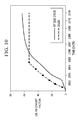
- FIG. 10 is a comparison of oil recovery factor between a SAGD and RF gas drive process.
- the A axis is time in years, and the Y axis is the oil recovery factor for the sector (SCTR).
- SCTR oil recovery factor for the sector
- FIG. 11 a - e illustrates various antenna and well configurations for the RF gas drive recovery process.
- FIG. 11 f - j illustrates various antenna and well configurations for the RF gas cap recovery process.
- This invention uses electromagnetic radiation to heat a heavy oil reservoir followed by gas injection. Fluids that are immobile at initial reservoir conditions can be heated with electromagnetic radiation to allow pressure communication across the reservoir. Once sufficient mobility is achieved, injected gas can be used to mobilize the heavy oil in any of the gas injection techniques available in the art or to be developed.
- the invention provides one or more embodiments, or any combination of embodiments, as described below:
- An improved gas injection oil recovery process comprising one or more producer wells and one or more gas injector wells, wherein injection of gas into said gas injector wells drives oil towards said producer wells for production of said oil, the improvement comprising preheating oil with electromagnetic radiation so as to provide fluid communication between said production well and said injection well before or during said gas injection.
- An improved gas injection oil recovery process comprising injecting gas into a reservoir to drive oil towards one or more producer wells for production of said oil, the improvement comprising EM preheating said oil before or during said gas injection.
- Gas injection can be at any suitable pressure, including is at a pressure above the minimum miscibility pressure (MMP), and below same.
- MMP minimum miscibility pressure
- Any suitable gas can be used, including air, CO2, N2, methane, ethane, propane, butane, flue gas, or combinations thereof.
- the injector and producer wells can be in any known or to be invented configurations, including wherein one or more producer wells are horizontal; wherein said gas injection provides a gas cap to maintain reservoir pressure while oil gravity drains to said production well; wherein the injection wells are vertical; wherein the injection wells are vertical and surround one or more production wells; wherein injection wells are horizontal; wherein injection wells are horizontal and above production wells; wherein 5 spot or 7 spot patterns are used; wherein regular arrays of wells are used; wherein staggered arrays of wells are used; and the like.
- the electromagnetic energy can provided by RF generator coupled via transmission lines to one or more antennae placed downhole in an oil reservoir.
- Antenna design can vary, and includes any known or invented antenna design, such as a dipole antenna, a half dipole plus n antenna, wherein n is a integer from ⁇ 0; and the like.
- Antenna placement can vary, including wherein said one or more antennae are positioned at or between wells; wherein said antennae are positioned on some or each injection well and some or each production well; and combinations thereof.
- the electromagnetic radiation can be any suitable frequency, including being generated by radio frequencies, microwave frequencies, combinations of frequencies, and the like.
- a method of enhanced oil recovery in another embodiment comprises providing at least one production well and at least one injection well in a subterranean reservoir containing heavy oil; providing at least one antenna in said subterranean reservoir, wherein said antenna is electrically connected to a current generator; emitting electromagnetic (EM) radiation from said antenna to develop fluid communication between said production well and said injection well; injecting gas into said injection well at a pressure sufficient to drive production of said heavy oil from said production well; and producing said heavy oil via said production well.
- EM electromagnetic
- the method can be combined with any enhanced oil recovery technique, including steam injection, gravity drive, in situ combustion, gas lift, gas cap, soak periods, cycles thereof, and/or combinations thereof.
- a method of enhanced oil recovery comprising providing at one or more production wells and one or more injection wells in a subterranean reservoir containing heavy oil; providing at least one antenna in each of said wells, wherein said antenna is electrically connected to a current generator capable of providing alternating current at radio frequencies (RF); emitting RF radiation from said antenna for a time sufficient to develop fluid communication between said one or more production wells and said one or more injection wells; injecting a gas into said one or more injection wells at a pressure sufficient to drive production of said heavy oil from said one or more production wells; and producing said heavy oil via said one or more production wells.
- RF radio frequencies
- FIG. 1 shows CO 2 flooding.
- pressure in a candidate reservoir has been depleted through primary production and possibly water flooding, it must be restored before CO 2 injection can begin.
- normally water is pumped into the reservoir through injection wells until pressure reaches a desired level, then CO 2 is introduced into the reservoir through these same injection wells.
- miscible front is generated by a gradual transfer of smaller, lighter hydrocarbon molecules from the oil to the CO 2 .
- This miscible front is in essence a bank of enriched gas that consists of CO 2 and light hydrocarbons. Under favorable conditions of pressure and temperature, this front will be soluble with the oil, making it less viscous and easier to move toward production wells.
- This initial CO 2 slug is typically followed by alternate water and CO 2 injection—the water serving to improve sweep efficiency and to minimize the amount of CO 2 required for the flood, but this may not be necessary in gravity based techniques.
- Production will be from an oil bank that forms ahead of the miscible front.
- the CO 2 can be separated from the produced fluids and may be reinjected, helping to reduce the amount of new CO 2 required for the project.
- the CO 2 can be both recycled and sequestered underground, reducing our overall carbon footprint. This procedure may be repeated until oil production drops below a profitable level.
- FIG. 2 shows nitrogen flooding.
- Gaseous nitrogen (N 2 ) is attractive for flooding because it can be manufactured on site at less cost than other alternatives. Since it can be extracted from air by cryogenic separation, there is an unlimited source, and being completely inert it is noncorrosive.
- FIG. 3 shows combined nitrogen and carbon dioxide flooding, which can be more cost effective than CO 2 alone because the nitrogen can be made onsite.
- nitrogen is injected into the reservoir to displace the CO 2 slug and its associated oil bank.
- FIG. 4 shows cyclic carbon dioxide flowing, which is similar in operation to the conventional cyclic or “huff-and-puff” steam injection process.
- CO 2 is injected into a well drilled into an oil reservoir, the well is shut-in for a time providing for a “soak period,” then is opened, allowing the oil and fluids to be produced.
- FIGS. 1-4 show vertical wells
- the same process can be used with horizontal wells, e.g., paired horizontal wells where oil gravity drains to the lower production well and one or more injection wells are placed near the top of the reservoir.
- a lower production well can be surrounded by a plurality of vertical injection wells.
- FIG. 5 An improvement of a basic gas injection technique is shown in FIG. 5 , which illustrates gas assisted gravity drainage or “GAGD.”
- GGD gas assisted gravity drainage
- CO 2 injected in vertical wells accumulates at the top of the pay zone and displaces oil, which drains to a horizontal producer straddling one or more injection wells.
- the CO 2 chamber grows downward and sideways, resulting in larger portions of the reservoir being swept without any increase in water saturation in the reservoir.
- the gravity segregation of CO 2 also helps in delaying, or even eliminating, CO 2 breakthrough to the producer as well as preventing the gas phase from competing for flow with oil.
- the gas injection wells do not have to be vertical, as shown in FIG.
- the RF antennae (not shown) can be placed on one or more of these wells or between wells, as shown in FIG. 11 .
- FIG. 6 shows another conventional gas drive operation, wherein the inventive improvement comprises preheating with RF (antennae not shown), thus allowing gas injectivity in a heavy oil reservoir.
- RF antennaless
- FIG. 7 shows a numerical simulation of a RF gas cap process in an Athabasca type reservoir. This particular graphic shows oil saturation after the gas cap has formed in the reservoir.
- two horizontal wells are drilled near the top of the formation fifty meters apart.
- a producer is drilled half way in between the two injectors near the bottom of the oil-bearing formation.
- Each of the three wells is equipped with a RF antenna for heating the formation.
- RF heating commences and bitumen is mobilized around all three wells until enough heat is transferred to the reservoir to create mobility or fluid communication between the wells.
- gas injection begins and creates a gas cap at the top of the reservoir.
- Injected gas can be any pure gas or mixture of gases, but in this simulation, methane was used to create the gas cap.
- This graphic shows oil saturation after start of gas injection—in this case, simulation was used to mimic 2 years of RF heating followed by methane injection of a 2D sector model of an offset injector producer development as shown in FIG. 11 g .
- Each grid block is 1 meter by 1 meter.
- Injection wells are located top right and left with a producer located bottom middle.
- Cell hatching represents oil saturation. Oil is being pushed toward production well by the injected gas. Initially all cells are at an initial oil saturation of 60-70% with 30 to 40% water except for the bottom two rows which are at a higher initial water saturation.
- oil from the upper sections have been displaced into the producer as shown by the change in oil saturation. Methane has replaced the displaced oil.
- FIG. 8 shows oil recovery in simulated experiments comparing steam assisted gravity drainage (SAGD) with the RF and gas injection method of FIG. 7 , and indicates that a much greater recovery is possible with the combined technique.
- SAGD steam assisted gravity drainage
- FIG. 9 shows a numerical simulation of a RF gas drive in an Athabasca type reservoir.
- two horizontal wells are drilled near the bottom of the formation fifty meters apart.
- a third is positioned at a higher elevation and at the midspan between the lower wells.
- Each of the wells is equipped with a RF antenna for heating the formation.
- 2 years of RF heating is simulated, followed by nitrogen injection.
- Cell hatching represents oil saturation.
- RF heating commences and initially bitumen may be produced from each well via gravity drainage until enough heat is transferred to the reservoir to create mobility between the wells.
- gas injection occurs and drives the mobile oil before it.
- Injected gas can be any pure gas or mixture of gases. Nitrogen is used in this simulation.
- the dissolved/mixed gas within the hydrocarbon starts to expand, partly because the elevation within the formation and partly because of the pressure drop at the production well. This gas expansion can also assist with lift.
- the gas pressure of the injected gas is maintained such that sufficient gas is dissolved or mixed in the hydrocarbons for gas drive purposes, but not oversaturate the hydrocarbon as to create a gas cap.
- a gas cap is used for part of the drive mechanism.
- the pressure is maintained at about 400 to 3500 p.s.i, preferably at about 400-1000 p.s.i, but the preferred range will be formation dependant.
- the amount of gas injected will depend upon formation conditions, the composition of the gas mixture, and the composition of the reservoir fluid. For example, if the injected gas is carbon dioxide, amount of CO 2 in the range of about 500 to 3500 s.c.f./barrel of oil-in-place can be used.
- the method can be combined with a second lower production well.
- the method can be combined with gravity drive mechanisms.
- the central well can be shut in and any remaining oil gravity drain to the lower well as shown in FIG. 9 .
- FIG. 10 shows the production profile predicted by a numerical simulation of the method depicted in FIG. 9 compared to SAGD. While initially lagging behind a SAGD development the RF GAS DRIVE process results in a net increase in production. Further optimization of this process can yield even higher percentage recovery.
- FIG. 11 shows the configuration of antennae, injection well and production wells suitable for various gas injection processes.
- Each subfigure represents a cross section of the pay zone with the axis of a horizontal well running perpendicular to the page.
- antenna can be placed near or on the side of any well or can be placed between wells.
- producers can be surrounded by injectors or not, and can be above, below or at the same depth as injectors. In preferred embodiments, the producers are below the injectors, so the method can take advantage of gravity drainage and or gas cap techniques. In other embodiments, at least one producer may be higher, to take advantage of gas expansion lift techniques, in yet others, horizontal sweeps are intended.
- FIG. 11 shows only 3 wells in each panel, the principles can be applied to five-spot or seven-spot patterns, or reverse patterns, and to line drive or staggered line drive and other well patterns as well.
- This method is also advantageous in thin pay zones since the primary recovery drive mechanism is displacement as opposed to gravity drainage. Gravity drainage processes are disadvantaged in thin pay zones since they require a vertical head to drive the process, which by definition is thin in thin pay zones.
- This invention will allow production from heavy oil and bitumen reservoirs that are currently considered uneconomic, reduce environmental impact by eliminating the need for source water for steam generation, and reduce capital costs for bitumen production facilities by removing water treatment and steam generation capabilities.
Landscapes
- Geology (AREA)
- Life Sciences & Earth Sciences (AREA)
- Engineering & Computer Science (AREA)
- Mining & Mineral Resources (AREA)
- Physics & Mathematics (AREA)
- Environmental & Geological Engineering (AREA)
- Fluid Mechanics (AREA)
- General Life Sciences & Earth Sciences (AREA)
- Geochemistry & Mineralogy (AREA)
- Chemical & Material Sciences (AREA)
- Chemical Kinetics & Catalysis (AREA)
- High Energy & Nuclear Physics (AREA)
- Production Of Liquid Hydrocarbon Mixture For Refining Petroleum (AREA)
Priority Applications (1)
| Application Number | Priority Date | Filing Date | Title |
|---|---|---|---|
| US13/729,474 US9458709B2 (en) | 2012-01-10 | 2012-12-28 | Heavy oil production with EM preheat and gas injection |
Applications Claiming Priority (3)
| Application Number | Priority Date | Filing Date | Title |
|---|---|---|---|
| US201261584963P | 2012-01-10 | 2012-01-10 | |
| US201261592366P | 2012-01-30 | 2012-01-30 | |
| US13/729,474 US9458709B2 (en) | 2012-01-10 | 2012-12-28 | Heavy oil production with EM preheat and gas injection |
Publications (2)
| Publication Number | Publication Date |
|---|---|
| US20130199774A1 US20130199774A1 (en) | 2013-08-08 |
| US9458709B2 true US9458709B2 (en) | 2016-10-04 |
Family
ID=48781810
Family Applications (1)
| Application Number | Title | Priority Date | Filing Date |
|---|---|---|---|
| US13/729,474 Active 2033-11-30 US9458709B2 (en) | 2012-01-10 | 2012-12-28 | Heavy oil production with EM preheat and gas injection |
Country Status (3)
| Country | Link |
|---|---|
| US (1) | US9458709B2 (fr) |
| CA (1) | CA2857211C (fr) |
| WO (1) | WO2013106205A1 (fr) |
Cited By (1)
| Publication number | Priority date | Publication date | Assignee | Title |
|---|---|---|---|---|
| US20170222297A1 (en) * | 2013-03-15 | 2017-08-03 | Chevron U.S.A. Inc. | Subsurface antenna for radio frequency heating |
Families Citing this family (23)
| Publication number | Priority date | Publication date | Assignee | Title |
|---|---|---|---|---|
| WO2013106205A1 (fr) | 2012-01-10 | 2013-07-18 | Conocophillips Company | Production de pétrole lourd par préchauffage électromagnétique et injection de gaz |
| US9103205B2 (en) | 2012-07-13 | 2015-08-11 | Harris Corporation | Method of recovering hydrocarbon resources while injecting a solvent and supplying radio frequency power and related apparatus |
| CA2886977C (fr) | 2012-10-02 | 2019-04-30 | Conocophillips Company | Em et stimulation de combustion de petrole lourd |
| US9644464B2 (en) | 2013-07-18 | 2017-05-09 | Saudi Arabian Oil Company | Electromagnetic assisted ceramic materials for heavy oil recovery and in-situ steam generation |
| US9869169B2 (en) | 2013-12-12 | 2018-01-16 | Husky Oil Operations Limited | Method to maintain reservoir pressure during hydrocarbon recovery operations using electrical heating means with or without injection of non-condensable gases |
| CN105756669B (zh) * | 2013-12-13 | 2019-06-18 | 中国工程物理研究院核物理与化学研究所 | 高含水水平井出水部位同位素标记测试方法 |
| CN103643942B (zh) * | 2013-12-13 | 2016-02-17 | 中国工程物理研究院核物理与化学研究所 | 高含水水平井出水部位同位素标记测试方法 |
| CN105756670B (zh) * | 2013-12-13 | 2019-06-18 | 中国工程物理研究院核物理与化学研究所 | 高含水水平井出水部位同位素标记测试方法 |
| MX2016009645A (es) * | 2014-01-24 | 2016-11-08 | Landmark Graphics Corp | Propiedades optimizadas de dispositivo de control de flujo para la inyeccion de gas acumulado. |
| US9856724B2 (en) | 2014-12-05 | 2018-01-02 | Harris Corporation | Apparatus for hydrocarbon resource recovery including a double-wall structure and related methods |
| WO2017140629A1 (fr) * | 2016-02-16 | 2017-08-24 | Shell Internationale Research Maatschappij B.V. | Système et procédé de récupération améliorée de pétrole combinée à une extraction au gaz |
| RO134124A2 (ro) * | 2016-04-08 | 2020-05-29 | John A. Babcock | Recuperare îmbunătăţită a petrolului pe bază de solvent miscibil |
| CA3024884A1 (fr) * | 2016-05-17 | 2017-11-23 | Nano Gas Technologies, Inc. | Procedes permettant d'influer sur la separation |
| US10577533B2 (en) | 2016-08-28 | 2020-03-03 | Linde Aktiengesellschaft | Unconventional enhanced oil recovery |
| US10570715B2 (en) | 2017-08-18 | 2020-02-25 | Linde Aktiengesellschaft | Unconventional reservoir enhanced or improved oil recovery |
| US10822540B2 (en) * | 2017-08-18 | 2020-11-03 | Linde Aktiengesellschaft | Systems and methods of optimizing Y-Grade NGL unconventional reservoir stimulation fluids |
| US10724351B2 (en) | 2017-08-18 | 2020-07-28 | Linde Aktiengesellschaft | Systems and methods of optimizing Y-grade NGL enhanced oil recovery fluids |
| US11193359B1 (en) | 2017-09-12 | 2021-12-07 | NanoGas Technologies Inc. | Treatment of subterranean formations |
| CN110630234B (zh) * | 2018-06-21 | 2021-11-02 | 中国石油天然气股份有限公司 | 稠油热采井的注汽方法 |
| CN111852416A (zh) * | 2019-04-17 | 2020-10-30 | 中国石油天然气股份有限公司 | 块状多层位大倾角“四高”油藏注气重力辅助混相驱方法 |
| US11421516B2 (en) * | 2019-04-30 | 2022-08-23 | Sigl-G, Llc | Geothermal power generation |
| CN112240182B (zh) * | 2020-10-30 | 2022-08-05 | 中国石油天然气股份有限公司 | 非常规油藏采收率提高方法及系统 |
| US20230112608A1 (en) | 2021-10-13 | 2023-04-13 | Disruptive Oil And Gas Technologies Corp | Nanobubble dispersions generated in electrochemically activated solutions |
Citations (15)
| Publication number | Priority date | Publication date | Assignee | Title |
|---|---|---|---|---|
| US3106244A (en) | 1960-06-20 | 1963-10-08 | Phillips Petroleum Co | Process for producing oil shale in situ by electrocarbonization |
| US4148359A (en) * | 1978-01-30 | 1979-04-10 | Shell Oil Company | Pressure-balanced oil recovery process for water productive oil shale |
| US20030141073A1 (en) | 2002-01-09 | 2003-07-31 | Kelley Terry Earl | Advanced gas injection method and apparatus liquid hydrocarbon recovery complex |
| US20060289157A1 (en) * | 2005-04-08 | 2006-12-28 | Rao Dandina N | Gas-assisted gravity drainage (GAGD) process for improved oil recovery |
| US20080142230A1 (en) | 2006-12-19 | 2008-06-19 | Lau Philip Y | Enzyme enhanced oil recovery (EEOR) for water alternating gas (WAG) systems |
| US20100065265A1 (en) * | 2005-06-20 | 2010-03-18 | KSN Energy LLC | Method and apparatus for in-situ radiofrequency assisted gravity drainage of oil (ragd) |
| US20100243249A1 (en) * | 2009-03-25 | 2010-09-30 | Conocophillips Company | Method for accelerating start-up for steam assisted gravity drainage operations |
| US20100294488A1 (en) | 2009-05-20 | 2010-11-25 | Conocophillips Company | Accelerating the start-up phase for a steam assisted gravity drainage operation using radio frequency or microwave radiation |
| US20100294489A1 (en) * | 2009-05-20 | 2010-11-25 | Conocophillips Company | In-situ upgrading of heavy crude oil in a production well using radio frequency or microwave radiation and a catalyst |
| US20110061868A1 (en) * | 2009-09-11 | 2011-03-17 | Excelsior Energy Limited | System and Method for Enhanced Oil Recovery from Combustion Overhead Gravity Drainage Processes |
| GB2479195A (en) | 2010-04-01 | 2011-10-05 | Wireless Fibre Systems Ltd | Buoy supported underwater radio antenna |
| US20110247807A1 (en) * | 2010-04-09 | 2011-10-13 | Christopher Kelvin Harris | Electrodes for electrical current flow heating of subsurface formations with tapered copper thickness |
| US20110253363A1 (en) * | 2008-09-26 | 2011-10-20 | Conocophillips Company | Process for enhanced production of heavy oil using microwaves |
| US20120103635A1 (en) * | 2009-07-07 | 2012-05-03 | Sanders Aaron W | Dispersion compositions with nonionic surfactants for use in petroleum recovery |
| WO2013106205A1 (fr) | 2012-01-10 | 2013-07-18 | Conocophillips Company | Production de pétrole lourd par préchauffage électromagnétique et injection de gaz |
-
2012
- 2012-12-28 WO PCT/US2012/071948 patent/WO2013106205A1/fr not_active Ceased
- 2012-12-28 CA CA2857211A patent/CA2857211C/fr active Active
- 2012-12-28 US US13/729,474 patent/US9458709B2/en active Active
Patent Citations (15)
| Publication number | Priority date | Publication date | Assignee | Title |
|---|---|---|---|---|
| US3106244A (en) | 1960-06-20 | 1963-10-08 | Phillips Petroleum Co | Process for producing oil shale in situ by electrocarbonization |
| US4148359A (en) * | 1978-01-30 | 1979-04-10 | Shell Oil Company | Pressure-balanced oil recovery process for water productive oil shale |
| US20030141073A1 (en) | 2002-01-09 | 2003-07-31 | Kelley Terry Earl | Advanced gas injection method and apparatus liquid hydrocarbon recovery complex |
| US20060289157A1 (en) * | 2005-04-08 | 2006-12-28 | Rao Dandina N | Gas-assisted gravity drainage (GAGD) process for improved oil recovery |
| US20100065265A1 (en) * | 2005-06-20 | 2010-03-18 | KSN Energy LLC | Method and apparatus for in-situ radiofrequency assisted gravity drainage of oil (ragd) |
| US20080142230A1 (en) | 2006-12-19 | 2008-06-19 | Lau Philip Y | Enzyme enhanced oil recovery (EEOR) for water alternating gas (WAG) systems |
| US20110253363A1 (en) * | 2008-09-26 | 2011-10-20 | Conocophillips Company | Process for enhanced production of heavy oil using microwaves |
| US20100243249A1 (en) * | 2009-03-25 | 2010-09-30 | Conocophillips Company | Method for accelerating start-up for steam assisted gravity drainage operations |
| US20100294489A1 (en) * | 2009-05-20 | 2010-11-25 | Conocophillips Company | In-situ upgrading of heavy crude oil in a production well using radio frequency or microwave radiation and a catalyst |
| US20100294488A1 (en) | 2009-05-20 | 2010-11-25 | Conocophillips Company | Accelerating the start-up phase for a steam assisted gravity drainage operation using radio frequency or microwave radiation |
| US20120103635A1 (en) * | 2009-07-07 | 2012-05-03 | Sanders Aaron W | Dispersion compositions with nonionic surfactants for use in petroleum recovery |
| US20110061868A1 (en) * | 2009-09-11 | 2011-03-17 | Excelsior Energy Limited | System and Method for Enhanced Oil Recovery from Combustion Overhead Gravity Drainage Processes |
| GB2479195A (en) | 2010-04-01 | 2011-10-05 | Wireless Fibre Systems Ltd | Buoy supported underwater radio antenna |
| US20110247807A1 (en) * | 2010-04-09 | 2011-10-13 | Christopher Kelvin Harris | Electrodes for electrical current flow heating of subsurface formations with tapered copper thickness |
| WO2013106205A1 (fr) | 2012-01-10 | 2013-07-18 | Conocophillips Company | Production de pétrole lourd par préchauffage électromagnétique et injection de gaz |
Cited By (2)
| Publication number | Priority date | Publication date | Assignee | Title |
|---|---|---|---|---|
| US20170222297A1 (en) * | 2013-03-15 | 2017-08-03 | Chevron U.S.A. Inc. | Subsurface antenna for radio frequency heating |
| US10693237B2 (en) * | 2013-03-15 | 2020-06-23 | Chevron U.S.A. Inc. | Method of employing a subsurface antenna in two regions |
Also Published As
| Publication number | Publication date |
|---|---|
| CA2857211A1 (fr) | 2013-07-18 |
| US20130199774A1 (en) | 2013-08-08 |
| WO2013106205A1 (fr) | 2013-07-18 |
| CA2857211C (fr) | 2018-09-04 |
Similar Documents
| Publication | Publication Date | Title |
|---|---|---|
| US9458709B2 (en) | Heavy oil production with EM preheat and gas injection | |
| US10927655B2 (en) | Pressure assisted oil recovery | |
| Bayestehparvin et al. | Solvent-based and solvent-assisted recovery processes: state of the art | |
| CA2707283C (fr) | Procede d'extraction d'une huile visqueuse par chauffage electrique et injection de solvant | |
| US10851632B2 (en) | Heat scavenging method for thermal recovery process | |
| US10597579B2 (en) | Anti-retention agent in steam-solvent oil recovery | |
| CA2827655C (fr) | Combustion in situ apres un drainage par gravite au moyen de la vapeur (sagd) | |
| Li et al. | The experimental and numerical investigation of in situ re-energization mechanism of urea-assisted steam drive in superficial heavy oil reservoir | |
| US11156072B2 (en) | Well configuration for coinjection | |
| Razavifar et al. | EOR potentials in the poststeam-injected heavy oil reservoirs | |
| CA2851782C (fr) | Procede pour la recuperation des hydrocarbures grace a l'injection d'eau liquide chauffee utilisant le chauffage par radiofrequence | |
| US9328592B2 (en) | Steam anti-coning/cresting technology ( SACT) remediation process | |
| CN104271878B (zh) | 蒸汽防锥进/脊进技术补救方法 | |
| CN104024570A (zh) | 水平井行列式石油采收过程 | |
| Turta | Enhanced oil recovery field case studies: Chapter 18. In situ combustion | |
| OJHA | Enhanced Oil Recovery | |
| CA2976575C (fr) | Configuration de puits en vue de la coinjection | |
| Burger | In-situ recovery of oil from oil sands | |
| CA2815410A1 (fr) | Procede d'assainissement a technologie anti-cone/crete a vapeur | |
| Babayev | Simulation of heavy oil recovery by using Computer Modelling Group (CMG) | |
| US11326431B2 (en) | Dense aqueous gravity displacement of heavy oil | |
| Pemmadi et al. | Enhanced oil recovery | |
| Murad | Simulation of Heavy Oil Recovery by Using Computer Modelling Group (CMG) | |
| Meldau et al. | Experts Assess Status and Outlook for Thermal, Chemical, and CO2 Miscible Flooding Processes | |
| Pautz et al. | Review of EOR (enhanced oil recovery) project trends and thermal EOR (enhanced oil recovery) technology |
Legal Events
| Date | Code | Title | Description |
|---|---|---|---|
| AS | Assignment |
Owner name: CONOCOPHILLIPS COMPANY, TEXAS Free format text: ASSIGNMENT OF ASSIGNORS INTEREST;ASSIGNORS:SULTENFUSS, DANIEL RAY;TREINEN, RICHARD;SIGNING DATES FROM 20130206 TO 20130315;REEL/FRAME:030062/0324 |
|
| AS | Assignment |
Owner name: HARRIS CORPORATION, FLORIDA Free format text: ASSIGNMENT OF ASSIGNORS INTEREST;ASSIGNOR:TRAUTMAN, MARK A.;REEL/FRAME:030232/0935 Effective date: 20130305 |
|
| STCF | Information on status: patent grant |
Free format text: PATENTED CASE |
|
| MAFP | Maintenance fee payment |
Free format text: PAYMENT OF MAINTENANCE FEE, 4TH YEAR, LARGE ENTITY (ORIGINAL EVENT CODE: M1551); ENTITY STATUS OF PATENT OWNER: LARGE ENTITY Year of fee payment: 4 |
|
| MAFP | Maintenance fee payment |
Free format text: PAYMENT OF MAINTENANCE FEE, 8TH YEAR, LARGE ENTITY (ORIGINAL EVENT CODE: M1552); ENTITY STATUS OF PATENT OWNER: LARGE ENTITY Year of fee payment: 8 |