US9475541B2 - Brake and method for the installation thereof - Google Patents
Brake and method for the installation thereof Download PDFInfo
- Publication number
- US9475541B2 US9475541B2 US14/058,676 US201314058676A US9475541B2 US 9475541 B2 US9475541 B2 US 9475541B2 US 201314058676 A US201314058676 A US 201314058676A US 9475541 B2 US9475541 B2 US 9475541B2
- Authority
- US
- United States
- Prior art keywords
- rim brake
- brake
- vehicle
- longitudinal portion
- wedge element
- Prior art date
- Legal status (The legal status is an assumption and is not a legal conclusion. Google has not performed a legal analysis and makes no representation as to the accuracy of the status listed.)
- Expired - Fee Related, expires
Links
- 238000000034 method Methods 0.000 title abstract description 30
- 238000009434 installation Methods 0.000 title abstract description 26
- 239000012530 fluid Substances 0.000 description 20
- 238000003466 welding Methods 0.000 description 10
- 230000006870 function Effects 0.000 description 7
- 230000000670 limiting effect Effects 0.000 description 6
- 230000008569 process Effects 0.000 description 6
- 230000009467 reduction Effects 0.000 description 6
- -1 polyoxymethylene Polymers 0.000 description 5
- 230000009471 action Effects 0.000 description 4
- 238000005452 bending Methods 0.000 description 4
- 230000007423 decrease Effects 0.000 description 4
- 229920002430 Fibre-reinforced plastic Polymers 0.000 description 3
- 229910045601 alloy Inorganic materials 0.000 description 3
- 239000000956 alloy Substances 0.000 description 3
- 239000011151 fibre-reinforced plastic Substances 0.000 description 3
- 239000002184 metal Substances 0.000 description 3
- 229910052751 metal Inorganic materials 0.000 description 3
- 239000002480 mineral oil Substances 0.000 description 3
- 235000010446 mineral oil Nutrition 0.000 description 3
- 239000000203 mixture Substances 0.000 description 3
- 239000002861 polymer material Substances 0.000 description 3
- 229910001369 Brass Inorganic materials 0.000 description 2
- 229910000906 Bronze Inorganic materials 0.000 description 2
- LFQSCWFLJHTTHZ-UHFFFAOYSA-N Ethanol Chemical compound CCO LFQSCWFLJHTTHZ-UHFFFAOYSA-N 0.000 description 2
- 229930040373 Paraformaldehyde Natural products 0.000 description 2
- 239000010951 brass Substances 0.000 description 2
- 239000010974 bronze Substances 0.000 description 2
- 239000011248 coating agent Substances 0.000 description 2
- 238000000576 coating method Methods 0.000 description 2
- KUNSUQLRTQLHQQ-UHFFFAOYSA-N copper tin Chemical compound [Cu].[Sn] KUNSUQLRTQLHQQ-UHFFFAOYSA-N 0.000 description 2
- 230000003247 decreasing effect Effects 0.000 description 2
- 238000013461 design Methods 0.000 description 2
- 238000010586 diagram Methods 0.000 description 2
- 229920001971 elastomer Polymers 0.000 description 2
- 239000007788 liquid Substances 0.000 description 2
- 238000004519 manufacturing process Methods 0.000 description 2
- 238000012986 modification Methods 0.000 description 2
- 230000004048 modification Effects 0.000 description 2
- 239000003921 oil Substances 0.000 description 2
- 229920000642 polymer Polymers 0.000 description 2
- 229920006324 polyoxymethylene Polymers 0.000 description 2
- 239000004810 polytetrafluoroethylene Substances 0.000 description 2
- 229920001343 polytetrafluoroethylene Polymers 0.000 description 2
- 238000003908 quality control method Methods 0.000 description 2
- 230000003068 static effect Effects 0.000 description 2
- 238000012360 testing method Methods 0.000 description 2
- 238000002604 ultrasonography Methods 0.000 description 2
- 239000002699 waste material Substances 0.000 description 2
- 229910000838 Al alloy Inorganic materials 0.000 description 1
- OKTJSMMVPCPJKN-UHFFFAOYSA-N Carbon Chemical compound [C] OKTJSMMVPCPJKN-UHFFFAOYSA-N 0.000 description 1
- 229920000049 Carbon (fiber) Polymers 0.000 description 1
- VYZAMTAEIAYCRO-UHFFFAOYSA-N Chromium Chemical compound [Cr] VYZAMTAEIAYCRO-UHFFFAOYSA-N 0.000 description 1
- 229910000861 Mg alloy Inorganic materials 0.000 description 1
- 229910000831 Steel Inorganic materials 0.000 description 1
- 230000006978 adaptation Effects 0.000 description 1
- 239000000654 additive Substances 0.000 description 1
- 230000000996 additive effect Effects 0.000 description 1
- 238000004026 adhesive bonding Methods 0.000 description 1
- 150000001298 alcohols Chemical class 0.000 description 1
- 230000005540 biological transmission Effects 0.000 description 1
- 229910052799 carbon Inorganic materials 0.000 description 1
- 239000004917 carbon fiber Substances 0.000 description 1
- 229910052804 chromium Inorganic materials 0.000 description 1
- 239000011651 chromium Substances 0.000 description 1
- 238000004140 cleaning Methods 0.000 description 1
- 230000006835 compression Effects 0.000 description 1
- 238000007906 compression Methods 0.000 description 1
- 238000004590 computer program Methods 0.000 description 1
- 238000005520 cutting process Methods 0.000 description 1
- 238000011161 development Methods 0.000 description 1
- 239000000428 dust Substances 0.000 description 1
- 239000013013 elastic material Substances 0.000 description 1
- 239000000806 elastomer Substances 0.000 description 1
- 239000003822 epoxy resin Substances 0.000 description 1
- 238000011990 functional testing Methods 0.000 description 1
- 239000004519 grease Substances 0.000 description 1
- 238000010438 heat treatment Methods 0.000 description 1
- 238000007689 inspection Methods 0.000 description 1
- 238000011900 installation process Methods 0.000 description 1
- 239000000314 lubricant Substances 0.000 description 1
- 238000005461 lubrication Methods 0.000 description 1
- 238000007747 plating Methods 0.000 description 1
- 229920000647 polyepoxide Polymers 0.000 description 1
- 229920000151 polyglycol Polymers 0.000 description 1
- 239000010695 polyglycol Substances 0.000 description 1
- 229920001296 polysiloxane Polymers 0.000 description 1
- 230000003252 repetitive effect Effects 0.000 description 1
- 238000011160 research Methods 0.000 description 1
- 230000004044 response Effects 0.000 description 1
- 238000005096 rolling process Methods 0.000 description 1
- 238000007789 sealing Methods 0.000 description 1
- 238000000926 separation method Methods 0.000 description 1
- 229920002545 silicone oil Polymers 0.000 description 1
- 238000005476 soldering Methods 0.000 description 1
- 239000010959 steel Substances 0.000 description 1
- XLYOFNOQVPJJNP-UHFFFAOYSA-N water Substances O XLYOFNOQVPJJNP-UHFFFAOYSA-N 0.000 description 1
- 238000004804 winding Methods 0.000 description 1
Images



Classifications
-
- B—PERFORMING OPERATIONS; TRANSPORTING
- B62—LAND VEHICLES FOR TRAVELLING OTHERWISE THAN ON RAILS
- B62L—BRAKES SPECIALLY ADAPTED FOR CYCLES
- B62L3/00—Brake-actuating mechanisms; Arrangements thereof
- B62L3/02—Brake-actuating mechanisms; Arrangements thereof for control by a hand lever
- B62L3/023—Brake-actuating mechanisms; Arrangements thereof for control by a hand lever acting on fluid pressure systems
-
- B—PERFORMING OPERATIONS; TRANSPORTING
- B62—LAND VEHICLES FOR TRAVELLING OTHERWISE THAN ON RAILS
- B62L—BRAKES SPECIALLY ADAPTED FOR CYCLES
- B62L1/00—Brakes; Arrangements thereof
- B62L1/005—Brakes; Arrangements thereof constructional features of brake elements, e.g. fastening of brake blocks in their holders
-
- B—PERFORMING OPERATIONS; TRANSPORTING
- B62—LAND VEHICLES FOR TRAVELLING OTHERWISE THAN ON RAILS
- B62L—BRAKES SPECIALLY ADAPTED FOR CYCLES
- B62L1/00—Brakes; Arrangements thereof
- B62L1/02—Brakes; Arrangements thereof in which cycle wheels are engaged by brake elements
- B62L1/06—Brakes; Arrangements thereof in which cycle wheels are engaged by brake elements the wheel rim being engaged
- B62L1/10—Brakes; Arrangements thereof in which cycle wheels are engaged by brake elements the wheel rim being engaged by the elements moving substantially parallel to the wheel axis
- B62L1/14—Brakes; Arrangements thereof in which cycle wheels are engaged by brake elements the wheel rim being engaged by the elements moving substantially parallel to the wheel axis the elements being mounted on levers pivotable about different axes
- B62L1/16—Brakes; Arrangements thereof in which cycle wheels are engaged by brake elements the wheel rim being engaged by the elements moving substantially parallel to the wheel axis the elements being mounted on levers pivotable about different axes the axes being located intermediate the ends of the levers
-
- Y—GENERAL TAGGING OF NEW TECHNOLOGICAL DEVELOPMENTS; GENERAL TAGGING OF CROSS-SECTIONAL TECHNOLOGIES SPANNING OVER SEVERAL SECTIONS OF THE IPC; TECHNICAL SUBJECTS COVERED BY FORMER USPC CROSS-REFERENCE ART COLLECTIONS [XRACs] AND DIGESTS
- Y10—TECHNICAL SUBJECTS COVERED BY FORMER USPC
- Y10T—TECHNICAL SUBJECTS COVERED BY FORMER US CLASSIFICATION
- Y10T29/00—Metal working
- Y10T29/49—Method of mechanical manufacture
- Y10T29/49826—Assembling or joining
Definitions
- the invention relates to a rim brake having a right arm and a left arm with, respectively, one upper and one lower longitudinal portion separated from one another by a pivot bearing.
- the lower longitudinal portion is provided for holding a brake pad and the upper longitudinal portion engages with at least one hydraulic cylinder.
- Such rim brakes are used for decelerating muscle-powered vehicles, for example, bicycles, scooters or tricycles.
- the invention also relates to a hydraulic vehicle brake having a master unit and a slave unit that are connected to a hydraulic line, the hydraulic line being filled with a hydraulic fluid.
- the invention furthermore relates to a method for the installation of a hydraulic brake with a master unit and a slave unit that are connected to a hydraulic line, comprising the following steps: severing the hydraulic line, installing the master unit on the vehicle, installing the slave unit on the vehicle, laying the hydraulic line on the vehicle, and connecting the master unit and/or slave unit to the hydraulic line.
- German Patent Application DE 42 20 854 A1 discloses a prior art rim brake.
- the hydraulic cylinder is disposed substantially horizontally, so as to be fastened with one end to the right arm and with the other end to the left arm.
- this brake has a large structural space and poor aerodynamics with a large amount of air turbulence.
- this rim brake has the disadvantage that, during installation on the vehicle, in some installation situations, the brake line must be dismounted from the master unit and/or slave unit and brake fluid can escape from the then free end of the hydraulic line. In this situation, cumbersome deaeration is necessary.
- the present invention provides a rim brake having a smaller structural space and improved aerodynamics.
- a rim brake be equipped with a right arm and a left arm situated on both sides of the wheel.
- Each arm has a pivot bearing by which it is rotatably mounted on a static part of the vehicle equipped with the rim brake.
- the right arm and the left arm are disposed approximately vertically, such that each arm is divided by the pivot bearing into an upper longitudinal portion and a lower longitudinal portion.
- the designation “right arm” and “left arm” is used in the present description merely to make a distinction between identical features.
- the actual configuration on the vehicle may vary depending on whether the vehicle brake is in a leading or trailing configuration or installed on the vehicle at the front wheel or at the rear wheel.
- Each of the arms may be produced in one piece, for example, as a forged part or as a fiber-reinforced plastic part.
- an arm may be a multi-part configuration and have at least one joint, for example, at the pivot bearing or at at least one of its ends.
- the joint may be formed by soldering, welding or adhesive bonding.
- the hydraulic cylinder required for moving the arms is disposed between the right arm and the left arm. This means that the hydraulic cylinder, the right arm, and the left arm are disposed approximately parallel to one another in an upright configuration and the hydraulic cylinder is disposed approximately in the plane spanned by the wheel of the vehicle.
- a wedge element through which the hydraulic cylinder and at least one arm of the rim brake are in engagement with one another.
- the hydraulic cylinder is configured to move the wedge element upward and downward along its movement direction.
- the spacing between the upper longitudinal portions of the arms varies in accordance with the position of the wedge element. Through the pivot bearing, this leads to a decrease or increase in the spacing between the lower longitudinal portions of the arms. If the lower longitudinal portions of the arms each bear a brake pad, these are moved with a predefinable force against the rotating friction partner, generally the rim flank, in order to generate a braking force.
- the pivot bearings are fastened to the vehicle frame, for example, as soldered-on parts. This makes it possible for the proposed rim brake to be used as a replacement part for a mechanical U-brake or V-brake such as is known per se.
- the upper longitudinal portion of the right or left arm is in sliding connection with the wedge element so that the spacing between the upper longitudinal portions can be increased or decreased as a result of a sliding movement up or down the wedge element.
- the wedge element and/or that portion part of the upper longitudinal portion of the arms that is in contact with the wedge element may be provided with a coating or a sliding element.
- a coating may comprise a hard chromium plating or a layer of diamond-like carbon.
- a sliding element may be composed of a ductile metal or an alloy (for example, brass or bronze) or of a polymer (for example, polyoxymethylene or polytetrafluoroethylene).
- the wedge element may be provided with a lubricant, for example, a grease, an oil, or silicone.
- the upper longitudinal portions of the arms may bear respectively at least one roller that, during a movement of the wedge element, can roll on a flank of the wedge element. In this way, the friction between the wedge element and the arms is minimized so that a large braking force can be attained with a low actuating force. Furthermore, in such an embodiment, the wear of the wedge element and/or of the upper longitudinal portion of the arms can be reduced to lengthen the service life of the rim brake.
- the roller may be equipped with a plain bearing, for example, a slide bush, which comprises a ductile metal or an alloy or a polymer.
- the slide bush may, in some embodiments of the invention, comprise brass, bronze, polytetrafluoroethylene, or polyoxymethylene.
- the at least one roller may be provided with an antifriction bearing, for example, a roller bearing or a ball bearing. Friction is further reduced in this way so that increased braking power can be attained.
- the wedge element may have at least one first flank and at least one second flank that run in different planes, wherein the right arm engages with the first flank and the left arm engages with the second flank.
- At least one flank of the wedge element may have a contour that is concave at least in sections and/or convex at least in sections and/or straight at least in sections.
- the characteristic of the brake that is to say the generated braking force as a function of the actuating force applied to the brake lever by the rider, can be adapted to different track profiles, different fields of application or different rider preferences.
- different wedge elements may be marketed as a set so that the user of the rim brake can select and exchange the wedge elements in accordance with their preferences.
- the rim brake furthermore comprises a spring element that acts on at least one arm so that the brake pad can be moved against the rotating friction partner counter to the spring force.
- the spring element may be a spiral spring that is disposed concentrically around the journal of the pivot bearing. This permits a protected installation position so that the brake is affected to a lesser extent by dust and moisture.
- the spring element may comprise a leaf spring that is fastened to an immovable part of the vehicle or to an immovable part of the rim brake and to the upper and/or lower longitudinal portion of the arm.
- a leaf spring permits a compact design of the pivot bearing to allow the rim brake to have an aerodynamic, elegant appearance.
- the pivot bearing may be disposed on a support that can be connected to the frame of a vehicle. This permits simple fastening to the frame using only one fastening screw, and also permits the exchange of conventional mechanical rim brakes for the rim brake according to the invention. Furthermore, such an embodiment eliminates the need for special attachment parts on the frame, thus permitting a broad range of applicability to different vehicle models.
- the leaf spring may be fastened to the support and to the upper longitudinal portion of the arm. This yields a compact design in which all parts are captively fastened to the rim brake so that said parts do not become detached during transportation, sale, and installation.
- the support may have a first web and a second web, wherein a journal of the pivot bearing is held both in the first and also in the second web.
- the central web may serve for fastening and/or for supporting the hydraulic cylinder.
- the hydraulic cylinder may be a double-acting hydraulic cylinder so that the arms can be moved hydraulically in both movement directions.
- the rim brake can, without a spring element, be moved from an open position into a closed position and from the closed position back into the open position.
- At least one of the arms may have a concave inner side that at least partially encloses the hydraulic cylinder. This yields an aerodynamically expedient casing around the hydraulic cylinder and/or the wedge element so that the air resistance of the proposed rim brake is further reduced.
- the hydraulic brake comprises at least one master unit and one slave unit that are connected to a hydraulic line.
- the master cylinder, the slave cylinder, and the hydraulic line are filled with an incompressible liquid as hydraulic fluid, for example, a liquid with at least one mineral oil or at least one silicone oil or at least one alcohol or a mixture of several polyglycols.
- an incompressible liquid as hydraulic fluid, for example, a liquid with at least one mineral oil or at least one silicone oil or at least one alcohol or a mixture of several polyglycols.
- the stated components master unit, slave unit, and hydraulic line are usually already connected to one another and filled with the hydraulic fluid as part of the production process at the factory. This firstly permits simple installation on the vehicle by the end user or the manufacturer of the vehicle, and permits operation of the brake for test purposes at the final inspection station or for the purposes of quality control.
- the slave unit may comprise a disc brake caliper that can be fastened, for example, to the fork tube or to the rear structure of a bicycle so that at least one brake pad can be placed in contact with a disc brake. If the hydraulic brake is a rim brake, the slave unit can be fastened at both sides of the wheels so that at least one brake pad can be placed in contact with the rim flanks.
- the master unit For the installation of the hydraulic brake on the vehicle, the master unit is installed at a location accessible to the rider so that, during operation of the vehicle, the rider can build up a brake pressure in the hydraulic line by the master unit.
- the slave unit is then installed on the vehicle to be placed in engagement with a rotating friction partner in order to generate the required braking force.
- the hydraulic line is laid on the vehicle so that it does not hinder the movement of movable vehicle parts and cannot be damaged during normal operation of the vehicle.
- the internal cross-section of the hydraulic line be reduced in at least one longitudinal portion. In some embodiments of the invention, this may be realized by squeezing or compressing the hydraulic line. In other embodiments of the invention, the hydraulic line may be welded, for example, by thermal welding, laser welding, or ultrasound welding. In some embodiments of the invention, the hydraulic line can be firstly compressed and then welded.
- the internal cross-section is to be understood to mean the cross-sectional area of the hydraulic line through which the hydraulic fluid flows during operation of the vehicle brake.
- the reduced internal cross-section is to be understood to mean the internal cross-section of the squeezed, pressed and/or welded longitudinal portion of the hydraulic line which prevents or at least hinders the throughflow of the hydraulic fluid.
- the reduction of the internal cross-section may take place multi-dimensionally, such that the external cross-section of the longitudinal section with reduced internal cross-section is of approximately polygonal form.
- the external cross-section of the longitudinal portion with reduced internal cross-section cannot exceed the original diameter of the hydraulic line, that is to say the circumscribed circle of the polygonal cross-section is smaller than the original diameter.
- the reduction in the internal cross-section may take place immediately before the installation of the hydraulic brake on the vehicle.
- the reduction of the internal cross-section may take place after the manufacture and functional testing of the hydraulic brake at the factory, such that the installer need merely sever the line at the intended point in order to be able to install the hydraulic brake on the vehicle.
- the hydraulic line may be severed at or adjacent to the longitudinal portion with reduced internal cross-section without the hydraulic fluid escaping from the hydraulic line.
- the at least one longitudinal portion with reduced internal cross-section can be severed from the hydraulic line.
- the remaining line length with the original internal cross-section can then be connected to the master unit or the slave unit such that the function of the hydraulic brake is restored.
- the installation of the hydraulic brake can be carried out without the risk of an undesired escape of hydraulic fluid from the open end of the hydraulic line.
- the hydraulic line Since the hydraulic line must be shortened by the longitudinal portion with reduced internal cross-section in any case before being reconnected to the master unit or slave unit, the hydraulic line can simultaneously be cut to the required length such that there is no excess line length remaining on the vehicle. This simultaneously improves the functioning and the aesthetics of the vehicle and of the brake system.
- At least one longitudinal portion with reduced internal cross-section may be disposed in the vicinity of the master unit and/or in the vicinity of the slave unit. Accordingly, for installation of the vehicle, the hydraulic line can be severed in the vicinity of the master unit before being connected to the master unit again after installation has taken place, or severed in the vicinity of the slave unit before being connected to the slave unit again after installation. In some embodiments of the invention, the hydraulic line may be severed at both sides, and, thus, laid or installed on the vehicle completely independently of the master unit and slave unit.
- the longitudinal portion of reduced internal cross-section is at a distance of approximately 1 cm to approximately 15 cm from the master unit and/or from the slave unit. This permits good accessibility with a suitable tool for severing the hydraulic line before installation. Secondly, the line length remaining after the severing process is adequate to permit the reconnection of the master unit and slave unit in most applications, and to keep the amount of waste material low.
- the internal cross-section may be reduced in two longitudinal portions that are at a distance of approximately 0.5 cm to approximately 3 cm from one another.
- the hydraulic line can be severed between the two longitudinal portions such that both ends are protected against the loss of hydraulic fluid. This permits particularly reliable reconnection of the hydraulic line, because there are no air inclusions in the two components to be connected.
- the laying of the hydraulic line on the vehicle may take place by virtue of the line being conducted through at least one orifice in a frame tube of the vehicle.
- the hydraulic line is in a protected location in the interior of the frame tube.
- the frame tube has two orifices which may be disposed in the vicinity of the master unit and in the vicinity of the slave unit or close to the two ends of the frame tube, for example the top tube, the down tube, or a rear stay of a bicycle, and through which the hydraulic line enters and exits.
- the method according to the invention permits particularly reliable installation because the hydraulic line is protected against loss of hydraulic fluid even when the free end thereof impacts against the inside of the frame tube during installation.
- the reduced internal cross-section may have a diameter of less than 0.5 mm, less than 0.3 mm, or less than 0.1 mm. In some embodiments of the invention, the reduced internal cross-section may be completely closed, such that the escape of hydraulic through the reduced internal cross-section is prevented completely.
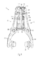
- FIG. 1 is a longitudinal cross-sectional view through a rim brake according to the present invention
- FIG. 2 is a fragmentary, perspective view of the rim brake of FIG. 1 from a side facing away from a frame;
- FIG. 3 is a fragmentary, perspective view of the rim brake of FIG. 1 from a fastening side thereof;
- FIG. 4 is a cross-sectional and perspective view of the rim brake of FIG. 1 ;
- FIG. 5 is an enlarged plan view of a detail of a wedge element and its arms of the rim brake of FIG. 1 ;
- FIG. 6 is a bottom plan view of the rim brake of FIG. 1 ;
- FIG. 7 is a side elevational view of the wedge element of FIG. 1 ;
- FIG. 8 is a perspective view of the wedge element of FIG. 1 ;
- FIG. 9 is a shows a diagrammatic illustration of a hydraulic brake according to the invention.
- FIG. 10 is a diagrammatic cross-sectional view through a hydraulic line of the hydraulic brake of FIG. 9 in a first longitudinal portion X-X;
- FIG. 11 is a diagrammatic cross-sectional view through the hydraulic line of the hydraulic brake of FIG. 9 at a second longitudinal portion Y-Y;
- FIG. 12 is a flow diagram of a method according to the invention.
- Relational terms such as first and second, top and bottom, and the like may be used solely to distinguish one entity or action from another entity or action without necessarily requiring or implying any actual such relationship or order between such entities or actions.
- the terms “comprises,” “comprising,” or any other variation thereof are intended to cover a non-exclusive inclusion, such that a process, method, article, or apparatus that comprises a list of elements does not include only those elements but may include other elements not expressly listed or inherent to such process, method, article, or apparatus.
- An element proceeded by “comprises . . . a” does not, without more constraints, preclude the existence of additional identical elements in the process, method, article, or apparatus that comprises the element.
- the term “about” or “approximately” applies to all numeric values, whether or not explicitly indicated. These terms generally refer to a range of numbers that one of skill in the art would consider equivalent to the recited values (i.e., having the same function or result). In many instances these terms may include numbers that are rounded to the nearest significant figure.
- program is defined as a sequence of instructions designed for execution on a computer system.
- a “program,” “software,” “application,” “computer program,” or “software application” may include a subroutine, a function, a procedure, an object method, an object implementation, an executable application, an applet, a servlet, a source code, an object code, a shared library/dynamic load library and/or other sequence of instructions designed for execution on a computer system.
- FIGS. 1 through 4 there is shown a first exemplary embodiment of a rim brake having a right arm 10 and a left arm 20 .
- the terms “right” and “left” have been selected merely by way of example in order to express that the arms are disposed on both sides of the rotating friction partner.
- the actual sides at which the right and left arms 10 , 20 are installed on the vehicle changes depend on whether the rim brake 1 is fastened to the frame of the vehicle in a trailing or leading configuration.
- Each arm has an upper longitudinal portion 101 , 201 and a lower longitudinal portion 102 , 202 . Between the two longitudinal portions there is disposed a pivot bearing 103 , 203 .
- the upper longitudinal portion 101 , the outer housing of the pivot bearing 103 and the lower longitudinal portion 102 may be produced in one piece, for example, as a cast or forged part.
- the right arm 10 and/or the left arm 20 may be produced from an aluminium alloy or a magnesium alloy or a high-grade steel.
- the arms 10 , 20 may be produced from fiber-reinforced plastic, for example, carbon fibers impregnated with an epoxy resin.
- the pivot bearings 103 , 102 may be fastened to the bicycle frame, for example, as soldered-on plinths.
- the pivot bearings 103 , 203 are disposed on a support 70 , which can be connected to the frame of a vehicle.
- a threaded bolt 75 that can be guided through a corresponding bore on the frame of the vehicle and screwed to a nut.
- the support 70 makes it possible for mechanical rim brakes known per se to be exchanged for the brake according to the invention because no additional attachment parts whatsoever need to be fastened to the frame of the vehicle.
- the lower longitudinal portions 102 , 202 of the arms 10 , 20 respectively bear one brake pad 30 that, as a static friction partner, is moved against the rotating friction partner and causes a reduction in the speed of the vehicle through the friction force generated.
- the brake pad 30 may be composed of a rubber mixture.
- the brake pad 30 may, in a manner known per se, have a profiling for dissipating water, such that braking performance is maintained even in wet weather.
- the brake pad 30 may be fastened to the arm 10 or 20 by a fastening screw 31 .
- slots 112 , 212 may be disposed in the arms 10 , 20 such that the brake pad 30 can be moved, and thereby adjusted, for adaptation to different frame sizes, different rim heights, and different frame geometries.
- the upper longitudinal portion 101 , 201 of the arms 10 , 20 has a convex outer contour and a concave inner form 120 such that the arms 10 , 20 at least partially surround the hydraulic cylinder 40 .
- the hydraulic cylinder 40 has a cylindrical basic body 46 .
- a piston 45 is held in a linearly movable manner in the basic body 46 .
- the piston 45 may have a sealing groove 48 in which a seal, composed, for example, of an elastomer, may be accommodated.
- the piston 45 is connected to a connecting rod 44 .
- the connecting rod 44 and the piston rod 45 may be produced in one piece, for example, as a cast part or as a turned part.
- the hydraulic cylinder 40 is closed off at its upper end by a cover 49 in which a seal 47 is held, which seals off the leadthrough point of the connecting rod 44 through the cover 49 .
- the hydraulic cylinder 40 can be charged with a hydraulic fluid, for example, a mineral oil, through a line 55 . This causes the piston 45 to be moved upward.
- a wedge element 50 Disposed on the end of the connecting rod 44 is a wedge element 50 .
- the wedge element 50 correspondingly moves upwards or downwards with the piston 45 .
- the wedge element 50 is connected through its flanks 501 , 502 to the upper longitudinal portions 101 , 201 of the arms 10 , 20 .
- Rotatably mounted rollers 110 , 111 are provided at the contact points between the arms 10 , 20 and the wedge element 50 to permit a low-wear and low-friction rolling movement as the wedge element 50 moves.
- the rollers 110 , 111 may be mounted by plain bearings 115 .
- the rollers 110 , 111 may also be omitted, such that the upper longitudinal portions 101 , 201 of the arms 10 , 20 are in sliding connection with the wedge element 50 .
- the spacing between the upper longitudinal portions 101 , 201 of the arms 10 , 20 increases. Due to the pivot bearings 103 , 203 , this movement causes the spacing between the lower longitudinal portions 102 , 202 to be decreased, such that the brake pads are moved into a braking position against the rotating friction partner.
- the piston 45 with the wedge element 50 is moved downward, the spacing between the upper longitudinal portions 101 , 102 decreases, such that the spacing between the lower longitudinal portions 102 , 202 increases and the brake pads 30 are released from the rotating friction partner.
- the brake 1 is then in an open position.
- spring elements 60 are provided.
- the spring elements 60 are formed as straight leaf springs as shown in FIG. 3 .
- the spring elements 60 are fastened in an orifice 61 on the support 70 and in an orifice 62 on the upper longitudinal portion 101 of the arm 10 .
- the relative distance between the two bores 61 , 62 decreases, such that the spring element 60 is deformed from a more straight position into a more curved, deflected position.
- the restoring force of the elastic material of the spring element 60 ensures that the brake pads 30 are moved from the braking position into the open position.
- the invention is self-evidently not restricted to the use of straight spring elements 60 .
- the spring element may also comprise a spiral spring with at least one winding.
- FIG. 5 shows a plan view of the upper longitudinal portions 101 , 201 of the arms 10 , 20 . It can be seen from FIG. 5 that the roller 110 is disposed approximately centrally on the cross-section of the upper longitudinal portion 101 of the right arm 10 . The roller 110 is mounted in a fork 115 such that the occurrence of bending moments acting on the bearing arrangement of the roller 110 is prevented.
- the fork 115 may be produced in one piece with the upper longitudinal portion 101 of the arm 10 , for example, as a cast or forged part.
- the upper longitudinal portion 201 of the left arm 20 has two rollers 111 a , 111 b . These, too, are mounted at both sides such that the bearing configuration of the rollers 111 is not subjected to bending moments.
- the wedge element 50 has a first flank 501 , which is in contact with the roller 110 , and two second flanks 502 a , 502 b , on which the associated rollers 111 a , 111 b roll.
- first flank 501 which is in contact with the roller 110
- second flanks 502 a , 502 b on which the associated rollers 111 a , 111 b roll.
- the roller 110 protrude, with the fork 115 , into the intermediate space between the rollers 111 a , 111 b , and thereby permit a smaller closing angle in the open position.
- FIG. 6 shows the rim brake in a view from below.
- FIG. 6 shows the support 70 , which has a first web 701 and a second web 702 .
- the webs 701 , 702 are connected by a central web 703 .
- the support 70 may be produced in one piece, for example, from a metal or an alloy or a fiber-reinforced plastic.
- the support 70 may be produced accordingly as a cast part or as a forged part or laminated in a mold.
- Fastened to the support 70 is a threaded bolt 75 , by which the support 70 and therefore the rim brake 1 can be fastened to the frame of a vehicle.
- the pivot bearings 103 , 203 which respectively have one rotary journal 705 .
- the rotary journal 705 may be guided through a bore in the second web 702 and screwed into a threaded bore in the first web 701 .
- the central web 703 serves, on the one hand, for connecting the two webs 701 , 702 .
- the hydraulic cylinder 40 can be supported with its underside on the central web 703 and thereby transmit to the frame of the vehicle the required opposing force to the movement of the wedge element 50 .
- the wedge element 50 has, on one side, two second flanks 502 a , 502 b which, through the rollers 111 a , 111 b , transmit the force to the second arm 20 . Disposed on the opposite side is a single first flank 501 which, through the roller 110 , transmits the actuating force to the right arm 10 .
- the first and second flanks 501 , 502 may have concave, convex, or rectilinear longitudinal portions so that the profile of the braking force can be variably selected as a function of the position of the piston.
- the wedge element 50 has a fastening orifice 505 by which the wedge element 50 is fastened to the connecting rod 44 of the hydraulic cylinder 40 .
- the fastening may be realized by an interference fit or a positively locking fit. In this way, the wedge element 50 can be easily exchanged in order, through the use of different wedge elements, to realize a different response behavior of the rim brake 1 so that the rim brake 1 can be adapted to different track profiles or different preferences of the rider.
- FIG. 9 shows a schematic illustration of a hydraulic brake.
- the hydraulic brake as per FIG. 9 can be used, in particular, on muscle-powered vehicles such as, for example, bicycles, recumbents, tricycles, or scooters.
- the hydraulic brake of FIG. 9 comprises at least one slave unit 100 which constitutes a part of a hydraulic rim brake known per se or of a hydraulic disc brake.
- the slave unit 100 is designed to move a brake pad against a rotating friction partner, in order thereby to generate a braking force for decelerating the vehicle, as a function of the pressure in the hydraulic system.
- the hydraulic brake further comprises a master unit 90 .
- the master unit 90 comprises, in a manner known per se, a hydraulic cylinder that is filled with a hydraulic fluid.
- the hydraulic cylinder is acted on by a hand-operated lever or a pedal, by which the user of the vehicle can exert a force on the piston of the hydraulic cylinder in order to build up a pressure in the hydraulic system and, thereby, control the braking force.
- the pressure or the braking force is transmitted through a hydraulic line 95 that connects the master unit 90 to the slave unit 100 .
- the hydraulic line may comprise a polymer material as a fluid-tight sheath or be composed of such a polymer material.
- the length of the hydraulic line 95 may be approximately 80 cm, approximately 170 cm, or approximately 250 cm depending on whether the hydraulic brake is used at the front or the rear wheel of a vehicle and depending on the length of the vehicle.
- the master unit 90 and the slave unit 100 may already be connected to the hydraulic line 95 at the factory. Likewise, these may already be charged with a hydraulic fluid, for example, a mineral oil, an alcohol, or a mixture of different oils or alcohols, at the factory. This allows the hydraulic brake to be functionally tested before delivery and permits simpler quality control.
- a hydraulic fluid for example, a mineral oil, an alcohol, or a mixture of different oils or alcohols
- the internal cross-section is reduced in at least one longitudinal portion 951 and/or 952 .
- this reduction of the cross-section may be realized by squeezing and/or welding the hydraulic line 95 in the longitudinal portion 951 and/or 952 .
- FIGS. 10 and 11 illustrate the cross-section along the sections X-X and Y-Y.
- FIG. 10 shows the unchanged internal cross-section 96 of the hydraulic line 95 .
- the cross-section 96 permits an unhindered circulation of the hydraulic fluid so that a braking force can be transmitted from the master unit 90 to the slave unit 100 .
- FIG. 11 shows the cross-section in the longitudinal portion 951 or 952 .
- the hydraulic line 95 has been squeezed from two sides so as to yield an approximately square cross-section 97 , the clear width of which is smaller than the clear width of the cross-section 96 as in FIG. 10 .
- the cross-section 97 may be completely closed off, such that no hydraulic fluid can pass through, a configuration that is shown in FIG. 11 .
- the cross-section 97 may additionally be welded by heating the polymer material of the hydraulic line 95 until it softens. The welding may be realized through contact with a heated squeezing tool, by ultrasound welding, or by laser welding. Other welding processes not explicitly mentioned here are self-evidently also possible.
- the original cross-section 98 of the hydraulic line is also illustrated in FIG. 11 .
- the cross-section of the hydraulic line 95 in the longitudinal portion 951 , 952 is smaller in all directions than the original cross-section 98 , such that the hydraulic line 95 can be installed on the vehicle and threaded through narrow orifices in a simple manner without the squeezed and/or welded cross-section posing a hindrance to the leadthrough of said hydraulic line.
- the reduced cross-section 97 is thus smaller or, at most, the same size as the original cross-section 98 , or in the case of a polygonal squeezed form, the original round cross-section 98 forms the circumscribed circle for the reduced cross-section 97 .
- the method according to the invention will be explained once again based upon the flow diagram in FIG. 12 .
- the hydraulic brake is firstly manufactured, subjected to final assembly, and tested in a manner known per se. Then, in the first method step 81 , the internal cross-section of the hydraulic line is reduced by squeezing and/or welding in a longitudinal portion 951 .
- the internal cross-section that is to say, the cross-section available for the flow of the fluid, may thereafter have a diameter of less than 0.5 mm, less than 0.3 mm, less than 0.1 mm, or 0 mm.
- the reduced internal cross-section that is to say the cross-section available for the flow of the hydraulic fluid, may thereafter have a diameter of less than 0.5 mm, less than 0.3 mm, less than 0.1 mm, or 0 mm.
- the flow of the hydraulic fluid in the hydraulic line 95 is thereby prevented entirely or at least considerably restricted.
- the master unit 90 , the slave unit 100 , and the hydraulic line 95 nevertheless, are still fixedly connected to one another so that they cannot be separated during possible transportation of the brake to the end user.
- the hydraulic line 95 is severed by sawing or cutting. If the internal cross-section has been reduced in two longitudinal portions 951 , 952 , the severing takes place preferably between these longitudinal portions. In another case, the hydraulic line 95 may be severed at a point between the longitudinal portion 951 and the slave unit 100 or between the longitudinal portion 951 and the master unit 90 .
- step 84 the master unit is installed at its final position on the vehicle.
- the slave unit is installed at its final position on the vehicle.
- the hydraulic line 95 is laid between the master unit and the slave unit.
- This method step may include leading the hydraulic line through at least one orifice in a frame tube.
- the free end of the hydraulic line 95 comes into contact with or abuts against the frame tube or is subjected to vibrations, it is nevertheless not possible for hydraulic fluid to escape because the cross-section has been reduced in the longitudinal portion 951 and/or in the longitudinal portion 952 .
- the fourth, fifth and sixth method steps 84 , 85 and 86 to be carried out in some other sequence.
- the hydraulic line 95 is severed again at the severing point 954 . Furthermore, the hydraulic line is opened up at the connection point 953 of the slave unit 100 . The longitudinal portion between the severing point 954 and the connection point 953 is discarded as waste. Finally, the hydraulic line 95 can be connected to the slave unit 100 to establish functionality.
- the hydraulic brake is, therefore, installed on the vehicle and ready for use, without the need to carry out renewed filling and/or deaeration of the hydraulic system.
Landscapes
- Engineering & Computer Science (AREA)
- Mechanical Engineering (AREA)
- Physics & Mathematics (AREA)
- Fluid Mechanics (AREA)
- Braking Arrangements (AREA)
- Valves And Accessory Devices For Braking Systems (AREA)
Priority Applications (1)
| Application Number | Priority Date | Filing Date | Title |
|---|---|---|---|
| US15/272,055 US9878760B2 (en) | 2011-04-19 | 2016-09-21 | Brake and method for the installation thereof |
Applications Claiming Priority (3)
| Application Number | Priority Date | Filing Date | Title |
|---|---|---|---|
| DE102011007652A DE102011007652A1 (de) | 2011-04-19 | 2011-04-19 | Bremse und Verfahren zu Ihrer Montage |
| DE102011007652.2 | 2011-04-19 | ||
| PCT/EP2012/056449 WO2012143261A2 (fr) | 2011-04-19 | 2012-04-10 | Frein et son procédé de montage |
Related Parent Applications (1)
| Application Number | Title | Priority Date | Filing Date |
|---|---|---|---|
| PCT/EP2012/056449 Continuation WO2012143261A2 (fr) | 2011-04-19 | 2012-04-10 | Frein et son procédé de montage |
Related Child Applications (1)
| Application Number | Title | Priority Date | Filing Date |
|---|---|---|---|
| US15/272,055 Continuation US9878760B2 (en) | 2011-04-19 | 2016-09-21 | Brake and method for the installation thereof |
Publications (2)
| Publication Number | Publication Date |
|---|---|
| US20140041971A1 US20140041971A1 (en) | 2014-02-13 |
| US9475541B2 true US9475541B2 (en) | 2016-10-25 |
Family
ID=45976368
Family Applications (2)
| Application Number | Title | Priority Date | Filing Date |
|---|---|---|---|
| US14/058,676 Expired - Fee Related US9475541B2 (en) | 2011-04-19 | 2013-10-21 | Brake and method for the installation thereof |
| US15/272,055 Expired - Fee Related US9878760B2 (en) | 2011-04-19 | 2016-09-21 | Brake and method for the installation thereof |
Family Applications After (1)
| Application Number | Title | Priority Date | Filing Date |
|---|---|---|---|
| US15/272,055 Expired - Fee Related US9878760B2 (en) | 2011-04-19 | 2016-09-21 | Brake and method for the installation thereof |
Country Status (5)
| Country | Link |
|---|---|
| US (2) | US9475541B2 (fr) |
| EP (2) | EP2848513B1 (fr) |
| DE (1) | DE102011007652A1 (fr) |
| TW (1) | TWI637876B (fr) |
| WO (1) | WO2012143261A2 (fr) |
Cited By (2)
| Publication number | Priority date | Publication date | Assignee | Title |
|---|---|---|---|---|
| US20170073036A1 (en) * | 2011-04-19 | 2017-03-16 | Gustav Magenwirth Gmbh & Co. Kg | Brake and Method for the Installation Thereof |
| US10981621B2 (en) | 2017-07-10 | 2021-04-20 | Gustav Magenwirth Gmbh & Co. Kg | Hydraulic line connection for a hydraulic brake for handlebar steering and handlebar with hydraulic brake |
Families Citing this family (10)
| Publication number | Priority date | Publication date | Assignee | Title |
|---|---|---|---|---|
| US8769793B2 (en) * | 2010-06-30 | 2014-07-08 | Fox Factory, Inc. | Methods and apparatus for structural reinforcement of vehicle suspension members |
| DE102011053178B3 (de) * | 2011-08-31 | 2012-11-29 | Klaus-Peter Kapp | Reibungsbremse mit einer senkrecht zur Zuspannrichtung wirkenden Aktoreinheit |
| USD724506S1 (en) * | 2013-05-10 | 2015-03-17 | Rex Group SA | Brake pad for a bicycle |
| US9453546B2 (en) * | 2014-08-28 | 2016-09-27 | Shimano Inc. | Bicycle braking system |
| US9950409B2 (en) * | 2015-02-25 | 2018-04-24 | Delaware Capital Formation, Inc. | Clamping device with removable handles |
| US9586646B2 (en) | 2015-03-20 | 2017-03-07 | Shimano Inc. | Bicycle rim brake |
| ITUB20152335A1 (it) * | 2015-07-21 | 2017-01-21 | Itt Italia Srl | Unita' frenante di veicolo, pastiglia freno e metodi associati |
| US10207767B2 (en) | 2015-09-10 | 2019-02-19 | Sram, Llc | Bicycle rim brake |
| DE102017127120A1 (de) * | 2017-11-17 | 2019-05-23 | Bpw Bergische Achsen Kg | Bremsanordnung für ein Nutzfahrzeug |
| IT202100025826A1 (it) | 2021-10-08 | 2023-04-08 | Milano Politecnico | Apparato di frenatura |
Citations (16)
| Publication number | Priority date | Publication date | Assignee | Title |
|---|---|---|---|---|
| DE549087C (de) | 1928-02-06 | 1932-04-22 | Hydraulic Brake Co | Schlauchkupplung mit Aussenhuelse und einem in das Schlauchende eingefuehrten besonderen Klemmteil |
| US2140752A (en) * | 1931-04-23 | 1938-12-20 | Bendix Brake Co | Brake |
| US3338337A (en) * | 1965-12-15 | 1967-08-29 | Elmer E Freeland | Hydraulic cycle brake |
| US3899057A (en) * | 1972-01-25 | 1975-08-12 | Dba Sa | Hydraulic control circuit |
| US4090739A (en) * | 1975-08-14 | 1978-05-23 | Yamaha Hatsudoki Kabushiki Kaisha | Vehicle anti-skid brake system including restricted by-pass flow passage |
| EP0023414A1 (fr) | 1979-07-27 | 1981-02-04 | Shimano Industrial Company Limited | Frein sur jante |
| FR2621003A1 (en) | 1987-09-29 | 1989-03-31 | Campagnolo Spa | Bicycle brake of the central pull type |
| EP0575720A1 (fr) | 1992-06-25 | 1993-12-29 | GUSTAV MAGENWIRTH GmbH & Co. | Frein hydraulique sur jante pour bicyclettes |
| DE4237110A1 (de) | 1992-11-03 | 1994-05-05 | Willi Waelte Elektronik Ingeni | Hydraulische Bremse für Fahrräder |
| US5417481A (en) * | 1992-04-24 | 1995-05-23 | Robert Bosch Gmbh | Hydraulic vehicle brake system with a hydraulic unit for wheel slop control |
| US5678665A (en) * | 1995-11-22 | 1997-10-21 | Moldex Plastics & Tool Inc. | Hydraulic brake system |
| US6374957B1 (en) * | 1998-12-09 | 2002-04-23 | Gustav Magenwirth Gmbh & Co. | Brake cylinder for a rim brake |
| US6651790B2 (en) * | 2002-04-29 | 2003-11-25 | Chih-Chen Juan | Hydraulic balanced braking system |
| US20100200340A1 (en) | 2006-07-17 | 2010-08-12 | Time Sport International | Braking device for a rimmed wheel, especially for a bike wheel |
| US20110290595A1 (en) * | 2010-05-27 | 2011-12-01 | Shimano, Inc. | Reversible hydraulic caliper brake for a bicycle |
| US20120067802A1 (en) * | 2010-09-16 | 2012-03-22 | Wallace Taylor Irvin | In-line fuel conditioner |
Family Cites Families (11)
| Publication number | Priority date | Publication date | Assignee | Title |
|---|---|---|---|---|
| DE3904132A1 (de) * | 1989-02-11 | 1990-08-16 | Bosch Gmbh Robert | Vorrichtung zur druckregulierung in einem hydraulischen system |
| DE3923282C2 (de) * | 1989-07-14 | 1998-04-30 | Bosch Gmbh Robert | Vorrichtung zur Dämpfung von Druckschwingungen |
| DE19544221A1 (de) * | 1995-11-28 | 1997-06-05 | Bosch Gmbh Robert | Dämpfer, insbesondere zur Dämpfung von Druckschwankungen in Bremsflüssigkeit hydraulischer Fahrzeugbremsanlagen |
| DE19929678B4 (de) * | 1999-06-28 | 2005-01-20 | Gustav Magenwirth Gmbh & Co. Kg | Bremszylinder für eine hydraulische Bremse |
| TW410784U (en) * | 1999-04-09 | 2000-11-01 | Ruan Jr Cheng | Improved structure of hydraulic brake |
| US6510926B1 (en) * | 2001-07-13 | 2003-01-28 | Shimano Inc. | Disc brake caliper assembly |
| US6647721B2 (en) * | 2001-11-07 | 2003-11-18 | Case, Llc | Hydraulic system for suppressing oscillation in heavy equipment |
| TW537275U (en) * | 2002-08-05 | 2003-06-11 | Dia Compe Taiwan Co Ltd | Disc brake device for bicycle |
| TWI229647B (en) * | 2003-06-09 | 2005-03-21 | Jr-Cheng Ruan | Hydraulic brake driving mechanism |
| DE102005061903A1 (de) * | 2005-12-23 | 2007-06-28 | Gustav Magenwirth Gmbh & Co. Kg | Anschlussstück und Bremszange |
| DE102011007652A1 (de) * | 2011-04-19 | 2012-10-25 | Gustav Magenwirth Gmbh & Co. Kg | Bremse und Verfahren zu Ihrer Montage |
-
2011
- 2011-04-19 DE DE102011007652A patent/DE102011007652A1/de not_active Withdrawn
-
2012
- 2012-04-10 EP EP14169832.4A patent/EP2848513B1/fr active Active
- 2012-04-10 WO PCT/EP2012/056449 patent/WO2012143261A2/fr not_active Ceased
- 2012-04-10 EP EP12715063.9A patent/EP2699468A2/fr not_active Withdrawn
- 2012-04-18 TW TW101113861A patent/TWI637876B/zh not_active IP Right Cessation
-
2013
- 2013-10-21 US US14/058,676 patent/US9475541B2/en not_active Expired - Fee Related
-
2016
- 2016-09-21 US US15/272,055 patent/US9878760B2/en not_active Expired - Fee Related
Patent Citations (18)
| Publication number | Priority date | Publication date | Assignee | Title |
|---|---|---|---|---|
| DE549087C (de) | 1928-02-06 | 1932-04-22 | Hydraulic Brake Co | Schlauchkupplung mit Aussenhuelse und einem in das Schlauchende eingefuehrten besonderen Klemmteil |
| US2140752A (en) * | 1931-04-23 | 1938-12-20 | Bendix Brake Co | Brake |
| US3338337A (en) * | 1965-12-15 | 1967-08-29 | Elmer E Freeland | Hydraulic cycle brake |
| US3899057A (en) * | 1972-01-25 | 1975-08-12 | Dba Sa | Hydraulic control circuit |
| US4090739A (en) * | 1975-08-14 | 1978-05-23 | Yamaha Hatsudoki Kabushiki Kaisha | Vehicle anti-skid brake system including restricted by-pass flow passage |
| EP0023414A1 (fr) | 1979-07-27 | 1981-02-04 | Shimano Industrial Company Limited | Frein sur jante |
| FR2621003A1 (en) | 1987-09-29 | 1989-03-31 | Campagnolo Spa | Bicycle brake of the central pull type |
| DE3825394A1 (de) | 1987-09-29 | 1989-04-06 | Campagnolo Spa | Fahrradbremse, insbesondere mittelzugbremse |
| US5417481A (en) * | 1992-04-24 | 1995-05-23 | Robert Bosch Gmbh | Hydraulic vehicle brake system with a hydraulic unit for wheel slop control |
| EP0575720A1 (fr) | 1992-06-25 | 1993-12-29 | GUSTAV MAGENWIRTH GmbH & Co. | Frein hydraulique sur jante pour bicyclettes |
| US5368136A (en) * | 1992-11-03 | 1994-11-29 | Walte; Willi | Hydraulic brakes for bicycles |
| DE4237110A1 (de) | 1992-11-03 | 1994-05-05 | Willi Waelte Elektronik Ingeni | Hydraulische Bremse für Fahrräder |
| US5678665A (en) * | 1995-11-22 | 1997-10-21 | Moldex Plastics & Tool Inc. | Hydraulic brake system |
| US6374957B1 (en) * | 1998-12-09 | 2002-04-23 | Gustav Magenwirth Gmbh & Co. | Brake cylinder for a rim brake |
| US6651790B2 (en) * | 2002-04-29 | 2003-11-25 | Chih-Chen Juan | Hydraulic balanced braking system |
| US20100200340A1 (en) | 2006-07-17 | 2010-08-12 | Time Sport International | Braking device for a rimmed wheel, especially for a bike wheel |
| US20110290595A1 (en) * | 2010-05-27 | 2011-12-01 | Shimano, Inc. | Reversible hydraulic caliper brake for a bicycle |
| US20120067802A1 (en) * | 2010-09-16 | 2012-03-22 | Wallace Taylor Irvin | In-line fuel conditioner |
Non-Patent Citations (2)
| Title |
|---|
| International Search Report of PCT/EP2012/056449 dated Jan. 14, 2013. |
| www.magura.com, "Workshop 2011," copyrighted 2010. |
Cited By (3)
| Publication number | Priority date | Publication date | Assignee | Title |
|---|---|---|---|---|
| US20170073036A1 (en) * | 2011-04-19 | 2017-03-16 | Gustav Magenwirth Gmbh & Co. Kg | Brake and Method for the Installation Thereof |
| US9878760B2 (en) * | 2011-04-19 | 2018-01-30 | Gustav Magenwirth Gmbh & Co. Kg | Brake and method for the installation thereof |
| US10981621B2 (en) | 2017-07-10 | 2021-04-20 | Gustav Magenwirth Gmbh & Co. Kg | Hydraulic line connection for a hydraulic brake for handlebar steering and handlebar with hydraulic brake |
Also Published As
| Publication number | Publication date |
|---|---|
| US20140041971A1 (en) | 2014-02-13 |
| US9878760B2 (en) | 2018-01-30 |
| US20170073036A1 (en) | 2017-03-16 |
| TW201242835A (en) | 2012-11-01 |
| EP2848513A1 (fr) | 2015-03-18 |
| WO2012143261A3 (fr) | 2013-03-21 |
| EP2848513B1 (fr) | 2019-11-13 |
| EP2699468A2 (fr) | 2014-02-26 |
| WO2012143261A2 (fr) | 2012-10-26 |
| DE102011007652A8 (de) | 2015-10-29 |
| DE102011007652A1 (de) | 2012-10-25 |
| TWI637876B (zh) | 2018-10-11 |
Similar Documents
| Publication | Publication Date | Title |
|---|---|---|
| US9878760B2 (en) | Brake and method for the installation thereof | |
| US8146716B2 (en) | Reservoir tank for hydraulic brake lever assembly | |
| CN109018155B (zh) | 盘式制动钳及盘式制动钳组件 | |
| US4391352A (en) | Brake system and apparatus and method therefor | |
| US10082158B2 (en) | Master cylinder fitting | |
| US8534428B2 (en) | One piece hydraulic disc brake caliper with one way plumbing | |
| TWI414691B (zh) | 用於液壓盤式制動器卡鉗的螺栓 | |
| US8365878B2 (en) | Hydraulic disc brake caliper with one way plumbing | |
| CA2814609A1 (fr) | Maitre-cylindre de frein hydraulique ayant une bague d'appui | |
| US20140083805A1 (en) | Disc brake caliper, brake pads and pad pin | |
| US7845473B2 (en) | Brake caliper structure of straddle seat off-road vehicle | |
| US20210362801A1 (en) | Piston assembly for human-powered vehicle | |
| CN111994060B (zh) | 一种智能控制复合制动装置及其制动方法 | |
| US20090200128A1 (en) | Hydraulic disc brake caliper with one way plumbing | |
| CN112984011B (zh) | 盘式制动钳 | |
| EP2574536B1 (fr) | Véhicule motorisé à deux roues | |
| US11572128B2 (en) | Piston assembly for human-powered vehicle | |
| CN222538966U (zh) | Cbs布置结构及摩托车 | |
| CN214029031U (zh) | 一种联动阀刹车系统 | |
| CN201573628U (zh) | 一种微车全盘式制动系统 | |
| CN211417228U (zh) | 一种赛车制动踏杆结构 | |
| CN110550135A (zh) | 采用具有转向导向功能的独立减震器的轻型前叉 | |
| KR20060131577A (ko) | 자동차용 트윈 캘리퍼 브레이크 | |
| KR20060038229A (ko) | 너클 브라켓과 호스의 연결구조 |
Legal Events
| Date | Code | Title | Description |
|---|---|---|---|
| AS | Assignment |
Owner name: GUSTAV MAGENWIRTH GMBH & CO. KG, GERMANY Free format text: ASSIGNMENT OF ASSIGNORS INTEREST;ASSIGNOR:HUJER, JOACHIM;REEL/FRAME:031829/0572 Effective date: 20131210 |
|
| ZAAA | Notice of allowance and fees due |
Free format text: ORIGINAL CODE: NOA |
|
| ZAAB | Notice of allowance mailed |
Free format text: ORIGINAL CODE: MN/=. |
|
| STCF | Information on status: patent grant |
Free format text: PATENTED CASE |
|
| MAFP | Maintenance fee payment |
Free format text: PAYMENT OF MAINTENANCE FEE, 4TH YEAR, LARGE ENTITY (ORIGINAL EVENT CODE: M1551); ENTITY STATUS OF PATENT OWNER: LARGE ENTITY Year of fee payment: 4 |
|
| FEPP | Fee payment procedure |
Free format text: MAINTENANCE FEE REMINDER MAILED (ORIGINAL EVENT CODE: REM.); ENTITY STATUS OF PATENT OWNER: LARGE ENTITY |
|
| LAPS | Lapse for failure to pay maintenance fees |
Free format text: PATENT EXPIRED FOR FAILURE TO PAY MAINTENANCE FEES (ORIGINAL EVENT CODE: EXP.); ENTITY STATUS OF PATENT OWNER: LARGE ENTITY |
|
| STCH | Information on status: patent discontinuation |
Free format text: PATENT EXPIRED DUE TO NONPAYMENT OF MAINTENANCE FEES UNDER 37 CFR 1.362 |
|
| FP | Lapsed due to failure to pay maintenance fee |
Effective date: 20241025 |