US9488067B2 - Aircraft anti-icing systems having deflector vanes - Google Patents
Aircraft anti-icing systems having deflector vanes Download PDFInfo
- Publication number
- US9488067B2 US9488067B2 US14/154,967 US201414154967A US9488067B2 US 9488067 B2 US9488067 B2 US 9488067B2 US 201414154967 A US201414154967 A US 201414154967A US 9488067 B2 US9488067 B2 US 9488067B2
- Authority
- US
- United States
- Prior art keywords
- flow
- chamber
- gas
- nozzle
- deflector
- Prior art date
- Legal status (The legal status is an assumption and is not a legal conclusion. Google has not performed a legal analysis and makes no representation as to the accuracy of the status listed.)
- Active, expires
Links
- 238000000034 method Methods 0.000 claims abstract description 13
- 239000003351 stiffener Substances 0.000 claims description 9
- 230000002787 reinforcement Effects 0.000 claims 2
- 230000003014 reinforcing effect Effects 0.000 claims 1
- 239000000463 material Substances 0.000 description 11
- 230000015572 biosynthetic process Effects 0.000 description 7
- 238000005755 formation reaction Methods 0.000 description 7
- 238000009826 distribution Methods 0.000 description 4
- 238000004519 manufacturing process Methods 0.000 description 4
- 229910052782 aluminium Inorganic materials 0.000 description 3
- XAGFODPZIPBFFR-UHFFFAOYSA-N aluminium Chemical compound [Al] XAGFODPZIPBFFR-UHFFFAOYSA-N 0.000 description 3
- 238000010438 heat treatment Methods 0.000 description 3
- 229910052751 metal Inorganic materials 0.000 description 3
- 239000002184 metal Substances 0.000 description 3
- 239000003381 stabilizer Substances 0.000 description 3
- 229910000838 Al alloy Inorganic materials 0.000 description 2
- RTAQQCXQSZGOHL-UHFFFAOYSA-N Titanium Chemical compound [Ti] RTAQQCXQSZGOHL-UHFFFAOYSA-N 0.000 description 2
- UQZIWOQVLUASCR-UHFFFAOYSA-N alumane;titanium Chemical compound [AlH3].[Ti] UQZIWOQVLUASCR-UHFFFAOYSA-N 0.000 description 2
- 230000009977 dual effect Effects 0.000 description 2
- 230000003116 impacting effect Effects 0.000 description 2
- 238000003892 spreading Methods 0.000 description 2
- 239000010936 titanium Substances 0.000 description 2
- 229910052719 titanium Inorganic materials 0.000 description 2
- 241000272517 Anseriformes Species 0.000 description 1
- 239000000853 adhesive Substances 0.000 description 1
- 230000001070 adhesive effect Effects 0.000 description 1
- 230000002411 adverse Effects 0.000 description 1
- 238000005452 bending Methods 0.000 description 1
- 230000003247 decreasing effect Effects 0.000 description 1
- 230000001419 dependent effect Effects 0.000 description 1
- 230000017525 heat dissipation Effects 0.000 description 1
- 238000012423 maintenance Methods 0.000 description 1
- 239000002245 particle Substances 0.000 description 1
- 230000003134 recirculating effect Effects 0.000 description 1
- 238000011144 upstream manufacturing Methods 0.000 description 1
Images




Classifications
-
- F—MECHANICAL ENGINEERING; LIGHTING; HEATING; WEAPONS; BLASTING
- F01—MACHINES OR ENGINES IN GENERAL; ENGINE PLANTS IN GENERAL; STEAM ENGINES
- F01D—NON-POSITIVE DISPLACEMENT MACHINES OR ENGINES, e.g. STEAM TURBINES
- F01D25/00—Component parts, details, or accessories, not provided for in, or of interest apart from, other groups
- F01D25/02—De-icing means for engines having icing phenomena
-
- B—PERFORMING OPERATIONS; TRANSPORTING
- B64—AIRCRAFT; AVIATION; COSMONAUTICS
- B64D—EQUIPMENT FOR FITTING IN OR TO AIRCRAFT; FLIGHT SUITS; PARACHUTES; ARRANGEMENT OR MOUNTING OF POWER PLANTS OR PROPULSION TRANSMISSIONS IN AIRCRAFT
- B64D15/00—De-icing or preventing icing on exterior surfaces of aircraft
- B64D15/02—De-icing or preventing icing on exterior surfaces of aircraft by ducted hot gas or liquid
- B64D15/04—Hot gas application
-
- F—MECHANICAL ENGINEERING; LIGHTING; HEATING; WEAPONS; BLASTING
- F02—COMBUSTION ENGINES; HOT-GAS OR COMBUSTION-PRODUCT ENGINE PLANTS
- F02C—GAS-TURBINE PLANTS; AIR INTAKES FOR JET-PROPULSION PLANTS; CONTROLLING FUEL SUPPLY IN AIR-BREATHING JET-PROPULSION PLANTS
- F02C7/00—Features, components parts, details or accessories, not provided for in, or of interest apart form groups F02C1/00 - F02C6/00; Air intakes for jet-propulsion plants
- F02C7/04—Air intakes for gas-turbine plants or jet-propulsion plants
- F02C7/047—Heating to prevent icing
-
- Y—GENERAL TAGGING OF NEW TECHNOLOGICAL DEVELOPMENTS; GENERAL TAGGING OF CROSS-SECTIONAL TECHNOLOGIES SPANNING OVER SEVERAL SECTIONS OF THE IPC; TECHNICAL SUBJECTS COVERED BY FORMER USPC CROSS-REFERENCE ART COLLECTIONS [XRACs] AND DIGESTS
- Y02—TECHNOLOGIES OR APPLICATIONS FOR MITIGATION OR ADAPTATION AGAINST CLIMATE CHANGE
- Y02T—CLIMATE CHANGE MITIGATION TECHNOLOGIES RELATED TO TRANSPORTATION
- Y02T50/00—Aeronautics or air transport
- Y02T50/60—Efficient propulsion technologies, e.g. for aircraft
-
- Y02T50/671—
Definitions
- This patent relates generally to aircraft anti-icing systems and, more particularly, to aircraft anti-icing systems having deflector vanes.
- Ice formation or accretion on the leading edge of an aircraft engine inlet may adversely affect air flow into the engine. Furthermore, ice formations near or on an inlet of an aircraft nacelle can detach and impact the engine fan blades potentially causing damage to the engine, thereby resulting in reduced performance and/or negatively impacting operating margins of the aircraft.
- Pneumatic thermal anti-icing systems route heated air to a chamber in the nacelle to heat the surface of the inlet to prevent the formation of ice. These anti-ice systems often have a nozzle supplying the heated air to the chamber.
- the heated air from the nozzle may cause areas of localized heat with corresponding localized high peak temperatures on the surface of the nacelle receiving the direct jet impingement, thereby causing damage to the surface (e.g., deformation, loss of structural strength or margins, etc.) and/or necessitating selection of relatively more expensive material(s) to withstand the high localized temperatures.
- One described example apparatus includes a skin on an inlet side of a nacelle of an aircraft defining an annular chamber, a gas delivery system disposed within the annular chamber to provide a first gas to mix with and entrain a second gas in the annular chamber to define a flow through the annular chamber, and a deflector vane disposed within the annular chamber to redirect the flow through the annular chamber.
- the second gas is at a different temperature from the first gas.
- Another described example apparatus includes a chamber in an outboard structure of an aircraft, a gas delivery system disposed within the chamber having an outlet to provide a gas to the chamber, the gas to define a flow through the chamber, and a deflector vane disposed within the chamber to redirect the flow through the chamber.
- the chamber is on a fore side of the outboard structure.
- One described example method includes receiving a gas into an inlet duct of an aircraft, the gas to define a flow through the inlet duct in a first flow path direction, and redirecting the flow in a second flow path direction within the inlet duct.
- FIG. 1 illustrates an example aircraft in which the examples disclosed herein can be implemented.
- FIG. 2A is a frontal cutaway view of an engine nacelle of an example anti-icing system in accordance with the teachings of this disclosure.
- FIG. 2B is a cross-sectional view of the example anti-icing system of FIG. 2A .
- FIG. 3A is a detail view of the frontal cutaway of the example anti-icing system of FIG. 2A .
- FIG. 3B is an isometric detail view of the example anti-icing system of FIG. 2A .
- FIG. 4A is another detail view of the frontal cutaway of the example anti-icing system of FIG. 2A .
- FIG. 4B is another isometric view of the example anti-icing system of FIG. 2A as viewed from the opposite side of the bulkhead.
- FIGS. 5A and 5B are views of the deflector vane of the example anti-icing system of FIGS. 2A, 2B, 3A, 3B, 4A and 4B .
- FIG. 6A is a view of another example anti-icing system with multiple vanes.
- FIG. 6B is an isometric view of the example anti-icing system of FIG. 6A .
- FIG. 6C is another isometric view of the example anti-icing system of FIGS. 6A and 6B as viewed from the opposite side of the bulkhead.
- FIG. 6D is a cross-sectional view of an engine inlet annulus of the example anti-icing system of FIGS. 6A, 6B and 6C .
- FIG. 7A is a frontal cutaway view of an engine nacelle inlet of another example anti-icing system.
- FIG. 7B is a detail view of the frontal cutaway of the anti-icing system of FIG. 7A .
- any part e.g., a layer, film, area, or plate
- positioned on e.g., positioned on, located on, disposed on, or formed on, etc.
- the referenced part is either in contact with the other part, or that the referenced part is above the other part with one or more intermediate part(s) located therebetween.
- Stating that any part is in contact with another part means that there is no intermediate part between the two parts.
- EIIPS Engine inlet ice protection systems
- a chamber e.g., inlet duct, annular chamber, etc.
- entrain cooler air to define a flow through the chamber to prevent the formation of ice. Ice formations may reduce performance of the aircraft by preventing air from flowing into the engine and may damage the engine (e.g., an ice slab detaching and impacting engine fan blades).
- the heated air is typically moved from the engine through a duct and into a nozzle located within the chamber.
- the heated air flows through the chamber, thereby heating the surrounding area and inlet surfaces to prevent the formation of ice.
- Many EIIPS systems allow the flow to move in a circulating motion through the chamber of the nacelle.
- the chamber may also have an exit port to allow a portion or all of the flow to exit as the flow circulates through the chamber.
- Anti-icing systems direct heated gas (e.g., air) into a chamber via a gas delivery system (e.g., a nozzle).
- a gas delivery system e.g., a nozzle
- Many known anti-icing systems employ a nozzle in the chamber to direct the heated gas into the chamber.
- the flow emerging from the nozzle directly impinges on a surface of an inlet (e.g., skin surface, lip skin, skin etc.), which at least partially defines the chamber. This flow impingement can cause localized heating (e.g., localized temperature rises, high peak temperatures, etc.) of the inlet surface (e.g., areas of thermal concentration).
- High peak temperatures associated with this flow impingement may cause significant damage to the skin surface and/or necessitate selection of relatively more expensive materials (e.g., titanium, etc.) instead of relatively inexpensive materials (e.g., aluminum, etc.) to withstand the higher peak temperatures.
- relatively more expensive materials e.g., titanium, etc.
- relatively inexpensive materials e.g., aluminum, etc.
- Other possible solutions to reduce peak localized temperatures, including specialized nozzles or special ducting, may be relatively expensive and negatively impact weight requirements.
- an example anti-icing system may implement a deflector vane, which may be located in an inlet chamber (e.g., duct) of a nacelle defined by a surface of an inlet.
- the deflector vane which may be mounted to a bulkhead or any other appropriate location in the inlet chamber, redirects the heated gas from the nozzle to prevent the formation of localized high temperature areas of the inlet by increasing flow distance and/or mixing with cooler gas before the gas impinges the inlet surface (i.e., increase viscous dissipation of the heated gas), and/or to heat a portion of the nacelle, thereby more effectively preventing ice from forming Numerous deflector vanes may be used to continuously deflect the heated gas.
- the deflector vanes may also be arranged to increase mixing of the heated gas with relatively cooler gas in the chamber to provide more even heat distribution of the inlet surface and/or the chamber.
- the improved heat distribution may allow more effective anti-icing due to more heat spreading to portions adjacent the chamber that would otherwise receive less heat.
- the example apparatus described herein eliminates the need to use more expensive materials for the inlet, eliminates the need for piccolo tubing routed throughout the chamber, reduces and/or eliminates the use of small ports (e.g., a showerhead configuration), potentially reduces bleed flow necessary to meet performance requirements, and reduces nozzle complexity as seen, for example, in the piccolo tubing nozzle described in U.S. Pat. No. 4,688,745, which is incorporated by reference in its entirety.
- These systems are expensive to produce, highly complex for maintenance and may impose significant cost and/or manufacturability risk to the airplane. In some cases, these systems may negatively impact weight requirements of the airplane.
- the example systems described herein substantially eliminate the need to limit peak air temperature exiting the engine via the EIIPS system, thereby allowing greater flexibility of engine parameters, control and design.
- Examples described herein are relatively low-cost and low-weight, low in design complexity and relatively easy and cost-effective to manufacture. Additionally, the examples described herein improve effectiveness of anti-icing systems and may be used and/or adapted to upgrade existing anti-icing systems.
- FIG. 1 illustrates an example aircraft 100 having stabilizers 102 and wings 104 attached to a fuselage 103 in which the examples described herein can be implemented.
- An engine nacelle 106 is attached to the wing 104 and has an inlet 108 (e.g., inlet lip skin) on an inlet side of the nacelle 106 , and defines an inlet opening 110 for an aircraft engine.
- the inlet opening 110 may be blocked by ice particles that form on the inlet 108 .
- the anti-icing system described herein may be applied to the nacelle 106 , any of the fins 102 , the wings 104 and/or any other exterior or outboard structure (e.g., a horizontal stabilizer, a wing strut, an engine strut, a canard stabilizer, etc.) of the fuselage 103 .
- any other exterior or outboard structure e.g., a horizontal stabilizer, a wing strut, an engine strut, a canard stabilizer, etc.
- FIG. 2A is a frontal cutaway view of an example anti-icing system 200 of an engine nacelle 201 in accordance with the teachings of this disclosure.
- the anti-icing system 200 may be applied to, for example, an outboard structure on a fore side of an aircraft (e.g., the aircraft 100 of FIG. 1 ).
- An arrow 202 generally indicates an upward or vertical direction and an arrow 204 generally indicates an inboard direction, as viewed from a forward perspective of a left engine, towards a fuselage of the aircraft to which the nacelle 201 is attached.
- An inlet 206 defines an inlet surface of the engine nacelle 201 .
- a cutaway 208 of the inlet 206 shows a bulkhead 210 onto which both a gas delivery system, which is an EIIPS nozzle 212 in this example, and a deflector vane 214 are mounted.
- the inlet 206 and the bulkhead 210 define an annular chamber (e.g., annular duct) 211 .
- the EIIPS nozzle 212 delivers a first gas (e.g, heated and/or compressed air) from an engine, which may or may not be mounted onto the nacelle 201 , into the annular chamber 211 .
- the first gas is delivered to the EIIPS nozzle 212 , via a duct from the engine, and heats the annular chamber 211 while entraining a second gas (e.g., a cooler gas and/or a gas at a different temperature from the first gas, etc.) to define a flow (e.g., a circulating flow) within the annular chamber 211 .
- a second gas e.g., a cooler gas and/or a gas at a different temperature from the first gas, etc.
- the anti-icing system 200 has an exit opening 216 through which a portion of or all of the flow may exit the annular chamber 211 as the flow circulates through the annular chamber 211 .
- the exit opening 216 may be located on any appropriate portion of the inlet 206 (e.g., inlet lip skin) or the flow and/or a portion of the flow may exit through the bulkhead 210 via ducting.
- the exit opening 216 may have a louvered outlet or any other appropriate outlet geometry.
- the annular chamber 211 may have numerous exit openings. Operation of the EIIPS nozzle 212 and the deflector vane 214 will be discussed in greater detail in connection with FIGS. 3A and 3B .
- FIG. 2B is a cross-sectional view of the example anti-icing system 200 along the line A-A of FIG. 2A .
- a relatively flat fastener surface 220 may be used to receive fasteners to attach the inlet 206 to the bulkhead 210 , thereby mounting the inlet 206 to the engine nacelle and, as mentioned above in connection with FIG. 2A , defining the annular chamber 211 .
- the fastener surface 220 allows removal and alignment of the inlet 206 to the nacelle of the aircraft.
- the bulkhead 210 has a contour 222 as viewed along the cross section.
- the bulkhead 210 may have a relatively flat surface as viewed along the cross-section.
- FIG. 3A is a detail view of the cutaway 208 of the example anti-icing system 200 of FIG. 2A .
- a dotted line 304 represents a flow of heated gas, which is air in this example, emerging from the EIIPS nozzle 212 in an example where there is no deflecting vane 214 to deflect the flow.
- the heated air impinges directly on a region 305 of the inlet 206 resulting in a highly concentrated heat zone (e.g., high peak temperature spot) at the region 305 .
- the addition of the deflector vane 214 allows the inlet 206 to experience decreased peak temperatures.
- the deflector vane 214 redirects the flow in a direction generally indicated by a line 306 to increase the flow distance to the inlet 206 and, thus, increase entrainment (e.g., mixing) and viscous dissipation of the high velocity jet with cooler air.
- increasing the flow path allows the heated air emerging from the EIIPS nozzle 212 to entrain a second gas (e.g., cooler air) from the annular chamber 211 before the flow impinges on a surface of the inlet 206 .
- a deflector vane reduced peak inlet temperatures by approximately 36° F., but increased minimum inlet temperatures by approximately 27° F. and, thus, more-effectively distributed thermal energy throughout the system.
- the heated air emerging from the EIIPS nozzle 212 impinges the deflector vane 214 instead of the region 305 on the inlet 206 and, thus, transfers heat to the deflector vane 214 .
- the heat transferred to the deflector vane 214 may further conduct into the bulkhead 210 .
- the flow redirection may be used to redirect the flow towards the inlet center, thereby heating the portions of the inlet 206 on an inner barrel of an engine inlet, which are more critical to preventing ice that can affect engine performance and/or damage the engine.
- FIG. 3B is an isometric detail view of the cutaway 208 of the example anti-icing system 200 of FIG. 2A .
- the bulkhead 210 may also have geometry 310 to substantially match the shape of the outer attach angle of the inlet 206 and to couple to the inlet 206 via fasteners.
- the inlet 206 may be made of aluminum or any other appropriate material.
- the anti-icing system 200 allows use of relatively inexpensive materials such as, for example, aluminum for the inlet 206 as opposed to, for example, titanium, which may be relatively expensive and difficult to fabricate.
- FIG. 4A is another detail view of the example anti-icing system 200 of FIG. 2A .
- the EIIPS nozzle 212 has a dual outlet 402 . While the dual outlet 402 is shown, any appropriate nozzle configuration may be used, including a single outlet, multiple nozzles, those described in U.S. Pat. No. 4,688,745, which is incorporated by reference in its entirety, etc.
- a dimension 404 may be any appropriate length dependent on a multitude of factors including, but not limited to, temperature and pressure of air exiting the EIIPS nozzle 212 , materials used in the chamber (e.g., thermal conductivity of the materials, etc.), design requirements including material selection, geometry of the inlet 206 , configuration of the EIIPS nozzle 212 , etc.
- a dimension 406 represented by “Y,” may be any appropriate dimension dictated by the aforementioned factors related to the dimension 404 .
- the deflector vane 214 may be fastened to the bulkhead 210 via fasteners. Alternatively, the deflector vane 214 may be welded, adhered, or attached through any other appropriate attachment methods.
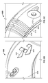
- FIG. 4B is another isometric view of the example anti-icing system 200 of FIG. 2A as viewed from the opposite side of the bulkhead 210 .
- a rear side of the EIIPS nozzle 212 mounts to the bulkhead 210 .
- the anti-icing system 200 may also include c-channel stiffeners 408 , mounted onto the bulkhead 210 on the opposite side of the deflector vane 214 to reinforce the bulkhead 210 and/or the deflector vane 214 , thereby preventing localized deformation to the bulkhead 210 and/or the deflector vane 214 as the flow emerging from the nozzle 212 impinges on the deflector vane 214 .
- the stiffeners 408 may also provide additional heat dissipation and/or spreading of heat from the air emerging out of the EIIPS nozzle 212 .
- the stiffeners 408 may be attached to the bulkhead and/or the deflector vane 214 via fasteners or attached through any other appropriate method of attachment (e.g., welded, adhered, etc.).
- the bulkhead 210 may also be reinforced through metal forming (i.e., producing forms to increase rigidity of the surface of the bulkhead 210 ).
- FIGS. 5A and 5B are views of the deflector vane 214 of the example anti-icing system 200 of FIGS. 2A, 2B, 3A, 3B, 4A and 4B .
- a dimension 502 represented by “R,” is a curvature radius.
- a dimension 504 represented by “A,” is the thickness of the deflector vane 214 .
- Dimensions 506 and 508 represented by “B” and “C” are edge-wise dimensions of the deflector vane 214 .
- the deflector vane 214 may be made of titanium aluminum alloy or any other appropriate material.
- the deflector vane 214 in this example, has a curved shape to redirect the flow. While the deflector vane 214 is depicted as having a curved shape, it may have other redirecting geometry including a straight angle, a relatively sharp angle, etc.
- FIG. 6A is a view of another example anti-icing system 600 with multiple vanes.
- a first deflector vane 602 is upstream of a second deflector vane 604 , which further re-directs the flow emerging from the EIIPS nozzle 212 .
- the deflector vanes 602 , 604 which are mounted onto a bulkhead 606 , have different geometries.
- the deflector vanes 602 , 604 may have substantially the same or substantially similar geometry (i.e., they may be the same fabricated part).
- the addition of the second vane 604 may allow additional heat removal from further flow redirection, which may result in a greater flow distance from the EIIPS nozzle 212 to an impingement point on the inlet 206 , thereby allowing increased flow entrainment with cooler air within the chamber and/or additional contact of the flow with the deflector vane 604 to remove additional heat.
- the deflector vanes 602 , 604 may be made of titanium aluminum alloy or any other appropriate material.
- a dimension 607 is the impingement distance from the EIIPS nozzle 212 to the deflector vane 602 .
- a dimension 608 is the vertical placement of the EIIPS nozzle 212 to the deflector vane 602 .
- a dimension 610 is the width of the plate.
- a dimension 612 is the distance from the impingement point to the edge of the deflector vane 602 .
- the dimensions 607 , 608 , 610 , 612 may be adjusted based on a multitude of factors including application, overall dimensions of the bulkhead 606 , gas temperature exiting the EIIPS nozzle 212 , number of deflector vanes, necessary entrainment distance, etc.
- FIG. 6B is an isometric view of the example anti-icing system 600 of FIG. 6A .
- the deflector vane 602 has a t-shaped reinforced structure, whereas the deflector vane 604 has an l-shaped structure.
- the deflector vanes 602 , 604 are mounted to the bulkhead 606 via fasteners (i.e., screwed onto the bulkhead 606 ).
- the deflector vanes 602 , 604 may be mounted to the bulkhead 606 by welds, adhesive or any appropriate attachment method.
- the deflector vanes 602 , 604 may be formed onto the bulkhead 606 through a bonding process or fabrication (e.g., sheet metal bending or forming, etc.). Additionally, more deflector vanes may be added to further redirect the flow from the EIIPS nozzle 212 , as needed.
- FIG. 6C is another isometric view of the example anti-icing system 600 of FIGS. 6A and 6B as viewed from the opposite direction of the bulkhead 606 .
- the anti-icing system 600 may also include stiffeners 616 to reinforce the deflector vanes 602 , 604 and/or the bulkhead 606 relative to the flow emerging from the EIIPS nozzle 212 .
- the stiffeners 616 may have a c-channel shape and may be fastened to the bulkhead 606 .
- the stiffeners 616 may be welded or adhered onto a surface the bulkhead 606 , or attached any other appropriate attachment method.
- the bulkhead 606 may also be reinforced through metal forming (i.e., producing forms to increase rigidity of the surface of the bulkhead 606 ).
- FIG. 6D is a cross-sectional view of an engine inlet annulus of the example anti-icing system 600 of FIGS. 6A, 6B and 6C .
- a dimension 620 represented by “H,” is a distance from a surface of the bulkhead 606 to the end of the deflector vane 602 .
- FIG. 7A is a frontal cutaway view of an engine nacelle 701 of another example anti-icing system 700 .
- the anti-icing system 700 may be applied to, for example, an outboard structure on a fore side of an aircraft (e.g., the aircraft 100 of FIG. 1 ).
- An arrow 702 generally indicates an upward or vertical direction and an arrow 704 generally indicates an inboard direction, as viewed from a forward perspective of a left engine towards a fuselage of the aircraft.
- An inlet 706 (e.g., inlet lip skin) defines an inlet surface.
- a cutaway 708 of the inlet 706 shows a bulkhead 710 to which, in this example, both the gas delivery system, which is the EIIPS nozzle 212 in this example, and deflector vanes 714 are mounted.
- the inlet 706 and the bulkhead 710 define an annular chamber 711 .
- the EIIPS nozzle 212 delivers a first gas (e.g., heated air) from an engine, which may be mounted in the nacelle 701 , into the annular chamber 711 .
- a first gas e.g., heated air
- the first gas may be delivered to the EIIPS nozzle 212 via a duct from the engine and heats the annular chamber 711 while entraining a second gas (e.g., a cooler gas and/or a gas at a different temperature from the first gas) to define a flow (e.g., a circulating flow) within the annular chamber 711 .
- a second gas e.g., a cooler gas and/or a gas at a different temperature from the first gas
- the inlet 706 may also include an outlet to allow a portion of the flow to exit the annular chamber 711 .
- FIG. 7B is a detailed view of the cutaway 708 of the anti-icing system 700 of FIG. 7A .
- the deflector vanes 714 in this example, increase the mixing of heated gas emerging from the EIIPS nozzle 212 by redirecting recirculating flow into the heated gas emerging from the EIIPS nozzle 212 . As the flow circulates through the annular chamber 711 , the deflector vanes 714 may also increase mixing of the gas by redirecting and/or interrupting the flow at various locations in the annular chamber 711 .
- any appropriate number of deflector vanes at any appropriate position relative to the EIIPS nozzle 212 may be used (e.g., the arrangement of deflector vanes 714 may be in front of the EIIPS nozzle 212 ).
- the deflector vanes 714 may be used in conjunction with the deflector vane 214 of the anti-icing system 200 and/or the deflector vanes 602 , 604 or any other appropriate combination of the vanes 214 , 602 , 604 .
- the deflector vanes 714 and/or the bulkhead 710 may be reinforced by stiffeners and/or forms in the bulkhead 710 .
Landscapes
- Engineering & Computer Science (AREA)
- Chemical & Material Sciences (AREA)
- Combustion & Propulsion (AREA)
- Mechanical Engineering (AREA)
- General Engineering & Computer Science (AREA)
- Aviation & Aerospace Engineering (AREA)
- Turbine Rotor Nozzle Sealing (AREA)
Priority Applications (4)
| Application Number | Priority Date | Filing Date | Title |
|---|---|---|---|
| US14/154,967 US9488067B2 (en) | 2014-01-14 | 2014-01-14 | Aircraft anti-icing systems having deflector vanes |
| ES14184866T ES2765185T3 (es) | 2014-01-14 | 2014-09-16 | Sistemas contra la formación de hielo de aeronave que presentan paletas deflectoras |
| EP14184866.3A EP2894096B1 (fr) | 2014-01-14 | 2014-09-16 | Systèmes antigivrage d'avion comportant des aubes déflectrices |
| CA2865853A CA2865853C (fr) | 2014-01-14 | 2014-10-02 | Systemes d'antigivrage d'aeronefs munis d'aubes deflectrices |
Applications Claiming Priority (1)
| Application Number | Priority Date | Filing Date | Title |
|---|---|---|---|
| US14/154,967 US9488067B2 (en) | 2014-01-14 | 2014-01-14 | Aircraft anti-icing systems having deflector vanes |
Publications (2)
| Publication Number | Publication Date |
|---|---|
| US20150198061A1 US20150198061A1 (en) | 2015-07-16 |
| US9488067B2 true US9488067B2 (en) | 2016-11-08 |
Family
ID=51570279
Family Applications (1)
| Application Number | Title | Priority Date | Filing Date |
|---|---|---|---|
| US14/154,967 Active 2035-02-15 US9488067B2 (en) | 2014-01-14 | 2014-01-14 | Aircraft anti-icing systems having deflector vanes |
Country Status (4)
| Country | Link |
|---|---|
| US (1) | US9488067B2 (fr) |
| EP (1) | EP2894096B1 (fr) |
| CA (1) | CA2865853C (fr) |
| ES (1) | ES2765185T3 (fr) |
Cited By (8)
| Publication number | Priority date | Publication date | Assignee | Title |
|---|---|---|---|---|
| US20170058772A1 (en) * | 2015-08-26 | 2017-03-02 | Rohr, Inc | Injector nozzle configuration for swirl anti-icing system |
| US20170210475A1 (en) * | 2016-01-27 | 2017-07-27 | General Electric Company | Nozzle and vane system for nacelle anti-icing |
| US10458275B2 (en) | 2017-01-06 | 2019-10-29 | Rohr, Inc. | Nacelle inner lip skin with heat transfer augmentation features |
| US11002188B2 (en) | 2018-09-14 | 2021-05-11 | Rohr, Inc. | Nozzle for an aircraft propulsion system |
| US11220344B2 (en) | 2018-12-17 | 2022-01-11 | Rohr, Inc. | Anti-ice double walled duct system |
| US11383846B2 (en) * | 2019-03-28 | 2022-07-12 | Bombardier Inc. | Aircraft wing ice protection system and method |
| US11613373B2 (en) | 2020-03-13 | 2023-03-28 | Rohr, Inc. | Nozzle for a thermal anti-icing system |
| US12410750B1 (en) | 2024-11-25 | 2025-09-09 | Honeywell International Inc. | Shielded swirl gas turbine engine inlet anti-icing system |
Families Citing this family (5)
| Publication number | Priority date | Publication date | Assignee | Title |
|---|---|---|---|---|
| US9488067B2 (en) | 2014-01-14 | 2016-11-08 | The Boeing Company | Aircraft anti-icing systems having deflector vanes |
| US9950799B2 (en) * | 2016-03-09 | 2018-04-24 | Honeywell International Inc. | Shielded anti-icing system and methods |
| US11465758B2 (en) | 2019-04-30 | 2022-10-11 | Rohr, Inc. | Method and apparatus for aircraft anti-icing |
| US11167855B2 (en) * | 2019-04-30 | 2021-11-09 | Rohr, Inc. | Method and apparatus for aircraft anti-icing |
| US11279491B2 (en) * | 2019-04-30 | 2022-03-22 | Rohr, Inc. | Method and apparatus for aircraft anti-icing |
Citations (23)
| Publication number | Priority date | Publication date | Assignee | Title |
|---|---|---|---|---|
| US1827276A (en) * | 1927-12-21 | 1931-10-13 | Alfaro Heraclio | Aeroplane |
| US3933327A (en) * | 1974-08-30 | 1976-01-20 | Rohr Industries, Inc. | Aircraft anti-icing plenum |
| US3983962A (en) * | 1974-06-20 | 1976-10-05 | Volkswagenwerk Aktiengesellschaft | Frame members for vehicles |
| US4084029A (en) * | 1977-07-25 | 1978-04-11 | The Boeing Company | Sine wave beam web and method of manufacture |
| US4095417A (en) * | 1976-08-23 | 1978-06-20 | Avco Corporation | Apparatus for and method of suppressing infrared radiation emitted from gas turbine engine |
| US4688745A (en) | 1986-01-24 | 1987-08-25 | Rohr Industries, Inc. | Swirl anti-ice system |
| US4752049A (en) * | 1985-12-30 | 1988-06-21 | The Boeing Company | Leading edge slat/anti-icing system and method for airfoil |
| US5088277A (en) * | 1988-10-03 | 1992-02-18 | General Electric Company | Aircraft engine inlet cowl anti-icing system |
| US5114103A (en) | 1990-08-27 | 1992-05-19 | General Electric Company | Aircraft engine electrically powered boundary layer bleed system |
| US5257498A (en) | 1992-04-23 | 1993-11-02 | United Technologies Corporation | Efficient anti-ice exhaust vent |
| US5451015A (en) * | 1993-05-18 | 1995-09-19 | Bell Helicopter Textron Inc. | Crashworthy composite aircraft structure with integral fuel tank |
| US6267328B1 (en) | 1999-10-21 | 2001-07-31 | Rohr, Inc. | Hot air injection for swirling rotational anti-icing system |
| US6698691B2 (en) * | 2001-02-15 | 2004-03-02 | Airbus France | Process for de-icing by forced circulation of a fluid, an air intake cowling of a reaction motor and device for practicing the same |
| US6702233B1 (en) * | 2001-02-07 | 2004-03-09 | Rohr, Inc. | Airfoil anti-icing assembly and method |
| US7131612B2 (en) | 2003-07-29 | 2006-11-07 | Pratt & Whitney Canada Corp. | Nacelle inlet lip anti-icing with engine oil |
| US7210611B2 (en) * | 2004-10-21 | 2007-05-01 | The Boeing Company | Formed structural assembly and associated preform and method |
| US20090108134A1 (en) * | 2007-10-25 | 2009-04-30 | General Electric Company | Icing protection system and method for enhancing heat transfer |
| EP2204320A2 (fr) | 2008-12-31 | 2010-07-07 | General Electric Company | Procédé et appareil d'antigivrage pour avion |
| US7922126B2 (en) * | 2004-05-13 | 2011-04-12 | Airbus Deutschland Gmbh | Aircraft component exposed to streaming surrounding air |
| WO2011073561A1 (fr) | 2009-12-18 | 2011-06-23 | Airbus Operations Sas | Entree d'air d'une nacelle d'aeronef comprenant un traitement du givre optimise |
| US8240982B2 (en) * | 2006-03-24 | 2012-08-14 | Aircelle | Structure for an air inlet lip of an electric de-icing pod comprising an acoustic attenuation zone |
| US8413922B2 (en) * | 2007-12-21 | 2013-04-09 | Creuzet Aeronautique | Acoustic processing structure particularly adapted to the air inlet of an aircraft nacelle |
| EP2894096A1 (fr) | 2014-01-14 | 2015-07-15 | The Boeing Company | Systèmes antigivrage d'avion comportant des aubes déflectrices |
-
2014
- 2014-01-14 US US14/154,967 patent/US9488067B2/en active Active
- 2014-09-16 ES ES14184866T patent/ES2765185T3/es active Active
- 2014-09-16 EP EP14184866.3A patent/EP2894096B1/fr active Active
- 2014-10-02 CA CA2865853A patent/CA2865853C/fr active Active
Patent Citations (25)
| Publication number | Priority date | Publication date | Assignee | Title |
|---|---|---|---|---|
| US1827276A (en) * | 1927-12-21 | 1931-10-13 | Alfaro Heraclio | Aeroplane |
| US3983962A (en) * | 1974-06-20 | 1976-10-05 | Volkswagenwerk Aktiengesellschaft | Frame members for vehicles |
| US3933327A (en) * | 1974-08-30 | 1976-01-20 | Rohr Industries, Inc. | Aircraft anti-icing plenum |
| US4095417A (en) * | 1976-08-23 | 1978-06-20 | Avco Corporation | Apparatus for and method of suppressing infrared radiation emitted from gas turbine engine |
| US4084029A (en) * | 1977-07-25 | 1978-04-11 | The Boeing Company | Sine wave beam web and method of manufacture |
| US4752049A (en) * | 1985-12-30 | 1988-06-21 | The Boeing Company | Leading edge slat/anti-icing system and method for airfoil |
| US4688745A (en) | 1986-01-24 | 1987-08-25 | Rohr Industries, Inc. | Swirl anti-ice system |
| US5088277A (en) * | 1988-10-03 | 1992-02-18 | General Electric Company | Aircraft engine inlet cowl anti-icing system |
| US5114103A (en) | 1990-08-27 | 1992-05-19 | General Electric Company | Aircraft engine electrically powered boundary layer bleed system |
| US5257498A (en) | 1992-04-23 | 1993-11-02 | United Technologies Corporation | Efficient anti-ice exhaust vent |
| US5451015A (en) * | 1993-05-18 | 1995-09-19 | Bell Helicopter Textron Inc. | Crashworthy composite aircraft structure with integral fuel tank |
| US6267328B1 (en) | 1999-10-21 | 2001-07-31 | Rohr, Inc. | Hot air injection for swirling rotational anti-icing system |
| US6702233B1 (en) * | 2001-02-07 | 2004-03-09 | Rohr, Inc. | Airfoil anti-icing assembly and method |
| US6698691B2 (en) * | 2001-02-15 | 2004-03-02 | Airbus France | Process for de-icing by forced circulation of a fluid, an air intake cowling of a reaction motor and device for practicing the same |
| US7131612B2 (en) | 2003-07-29 | 2006-11-07 | Pratt & Whitney Canada Corp. | Nacelle inlet lip anti-icing with engine oil |
| US7922126B2 (en) * | 2004-05-13 | 2011-04-12 | Airbus Deutschland Gmbh | Aircraft component exposed to streaming surrounding air |
| US7210611B2 (en) * | 2004-10-21 | 2007-05-01 | The Boeing Company | Formed structural assembly and associated preform and method |
| US8240982B2 (en) * | 2006-03-24 | 2012-08-14 | Aircelle | Structure for an air inlet lip of an electric de-icing pod comprising an acoustic attenuation zone |
| US20090108134A1 (en) * | 2007-10-25 | 2009-04-30 | General Electric Company | Icing protection system and method for enhancing heat transfer |
| US8413922B2 (en) * | 2007-12-21 | 2013-04-09 | Creuzet Aeronautique | Acoustic processing structure particularly adapted to the air inlet of an aircraft nacelle |
| EP2204320A2 (fr) | 2008-12-31 | 2010-07-07 | General Electric Company | Procédé et appareil d'antigivrage pour avion |
| WO2011073561A1 (fr) | 2009-12-18 | 2011-06-23 | Airbus Operations Sas | Entree d'air d'une nacelle d'aeronef comprenant un traitement du givre optimise |
| US20120248249A1 (en) | 2009-12-18 | 2012-10-04 | Airbus Operations Sas | Air inlet of an aircraft nacelle including optimized frost treatment |
| US8783619B2 (en) * | 2009-12-18 | 2014-07-22 | Airbus Operations Sas | Air inlet of an aircraft nacelle including optimized frost treatment |
| EP2894096A1 (fr) | 2014-01-14 | 2015-07-15 | The Boeing Company | Systèmes antigivrage d'avion comportant des aubes déflectrices |
Non-Patent Citations (2)
| Title |
|---|
| Canadian Intellectual Property Office, "Examiner's Report," issued in connection with Canadian Patent Application No. 2,865,853, issued on Oct. 5, 2015, 3 pages. |
| European Patent Office, "Extended Search Report," issued in connection with European Patent Application No. 14184866.3, issued on May 18, 2015, 7 pages. |
Cited By (10)
| Publication number | Priority date | Publication date | Assignee | Title |
|---|---|---|---|---|
| US20170058772A1 (en) * | 2015-08-26 | 2017-03-02 | Rohr, Inc | Injector nozzle configuration for swirl anti-icing system |
| US10393020B2 (en) * | 2015-08-26 | 2019-08-27 | Rohr, Inc. | Injector nozzle configuration for swirl anti-icing system |
| US20170210475A1 (en) * | 2016-01-27 | 2017-07-27 | General Electric Company | Nozzle and vane system for nacelle anti-icing |
| US10167085B2 (en) * | 2016-01-27 | 2019-01-01 | General Electric Company | Nozzle and vane system for nacelle anti-icing |
| US10458275B2 (en) | 2017-01-06 | 2019-10-29 | Rohr, Inc. | Nacelle inner lip skin with heat transfer augmentation features |
| US11002188B2 (en) | 2018-09-14 | 2021-05-11 | Rohr, Inc. | Nozzle for an aircraft propulsion system |
| US11220344B2 (en) | 2018-12-17 | 2022-01-11 | Rohr, Inc. | Anti-ice double walled duct system |
| US11383846B2 (en) * | 2019-03-28 | 2022-07-12 | Bombardier Inc. | Aircraft wing ice protection system and method |
| US11613373B2 (en) | 2020-03-13 | 2023-03-28 | Rohr, Inc. | Nozzle for a thermal anti-icing system |
| US12410750B1 (en) | 2024-11-25 | 2025-09-09 | Honeywell International Inc. | Shielded swirl gas turbine engine inlet anti-icing system |
Also Published As
| Publication number | Publication date |
|---|---|
| ES2765185T3 (es) | 2020-06-08 |
| CA2865853A1 (fr) | 2015-07-14 |
| EP2894096A1 (fr) | 2015-07-15 |
| CA2865853C (fr) | 2016-11-15 |
| US20150198061A1 (en) | 2015-07-16 |
| EP2894096B1 (fr) | 2019-11-06 |
Similar Documents
| Publication | Publication Date | Title |
|---|---|---|
| US9488067B2 (en) | Aircraft anti-icing systems having deflector vanes | |
| EP3216697B1 (fr) | Système anti-givrage et procédés | |
| US8690098B2 (en) | Air ejector nozzle tube for an oil heat exchanger of an aircraft engine | |
| US8100364B2 (en) | Anti-icing piccolo tube standoff | |
| US10393020B2 (en) | Injector nozzle configuration for swirl anti-icing system | |
| US6131855A (en) | Device for removing hot air for a jet engine air inlet cowl with a de-icing circuit | |
| EP3733504B1 (fr) | Dispositif de bord d'attaque pour aéronef | |
| EP3431395B1 (fr) | Système d'antigivrage commandé par éducteur | |
| US8371522B2 (en) | Device for cooling hot gas to be discharged from an aircraft | |
| JP2011505290A5 (fr) | ||
| US3246469A (en) | Cooling of aerofoil members | |
| US9701399B1 (en) | Parasitic drag induced boundary layer reduction system and method | |
| EP3205580B1 (fr) | Système antigivrage et aéronef | |
| WO2015198296A2 (fr) | Structure d'admission d'air et système de commande de flux d'air | |
| JP2017141015A (ja) | ナセル防氷のためのノズル及びベーンシステム | |
| CN111746801A (zh) | 飞机机翼冰保护系统和方法 | |
| CN102428004B (zh) | 用于飞机冷却系统的冷却器、飞机冷却系统和飞机冷却系统的操作方法 | |
| US10655539B2 (en) | Aircraft anti-icing system | |
| US8172178B2 (en) | Device for generating aerodynamic disturbances so as to protect the outer surface of an aircraft against elevated temperatures | |
| JP2013163480A (ja) | 防氷装置および航空機主翼 | |
| JP2013163479A (ja) | 防氷構造および航空機主翼 | |
| US20200102085A1 (en) | Device For Reducing Or Even Eliminating Tonal Noise For An Aircraft Powerplant De-Icing System | |
| US20140141705A1 (en) | Passive device for generating a film of cold air in contact with an outer surface of an aircraft | |
| US12091181B2 (en) | Aircraft engine attachment assembly | |
| EP3990351B1 (fr) | Agencement de bord d'attaque pour un aéronef |
Legal Events
| Date | Code | Title | Description |
|---|---|---|---|
| AS | Assignment |
Owner name: THE BOEING COMPANY, ILLINOIS Free format text: ASSIGNMENT OF ASSIGNORS INTEREST;ASSIGNORS:JOHNSON, RICK A;PHAM, VICTOR D;GALLY, DANIEL H;AND OTHERS;SIGNING DATES FROM 20140106 TO 20140113;REEL/FRAME:032205/0772 |
|
| FEPP | Fee payment procedure |
Free format text: PAYOR NUMBER ASSIGNED (ORIGINAL EVENT CODE: ASPN); ENTITY STATUS OF PATENT OWNER: LARGE ENTITY |
|
| STCF | Information on status: patent grant |
Free format text: PATENTED CASE |
|
| MAFP | Maintenance fee payment |
Free format text: PAYMENT OF MAINTENANCE FEE, 4TH YEAR, LARGE ENTITY (ORIGINAL EVENT CODE: M1551); ENTITY STATUS OF PATENT OWNER: LARGE ENTITY Year of fee payment: 4 |
|
| MAFP | Maintenance fee payment |
Free format text: PAYMENT OF MAINTENANCE FEE, 8TH YEAR, LARGE ENTITY (ORIGINAL EVENT CODE: M1552); ENTITY STATUS OF PATENT OWNER: LARGE ENTITY Year of fee payment: 8 |