US9488399B2 - Air conditioning apparatus - Google Patents
Air conditioning apparatus Download PDFInfo
- Publication number
- US9488399B2 US9488399B2 US14/390,776 US201314390776A US9488399B2 US 9488399 B2 US9488399 B2 US 9488399B2 US 201314390776 A US201314390776 A US 201314390776A US 9488399 B2 US9488399 B2 US 9488399B2
- Authority
- US
- United States
- Prior art keywords
- air conditioning
- heat exchanger
- conditioning apparatus
- refrigerant
- compressor
- Prior art date
- Legal status (The legal status is an assumption and is not a legal conclusion. Google has not performed a legal analysis and makes no representation as to the accuracy of the status listed.)
- Active
Links
Images




Classifications
-
- F—MECHANICAL ENGINEERING; LIGHTING; HEATING; WEAPONS; BLASTING
- F25—REFRIGERATION OR COOLING; COMBINED HEATING AND REFRIGERATION SYSTEMS; HEAT PUMP SYSTEMS; MANUFACTURE OR STORAGE OF ICE; LIQUEFACTION SOLIDIFICATION OF GASES
- F25B—REFRIGERATION MACHINES, PLANTS OR SYSTEMS; COMBINED HEATING AND REFRIGERATION SYSTEMS; HEAT PUMP SYSTEMS
- F25B49/00—Arrangement or mounting of control or safety devices
- F25B49/02—Arrangement or mounting of control or safety devices for compression type machines, plants or systems
-
- F—MECHANICAL ENGINEERING; LIGHTING; HEATING; WEAPONS; BLASTING
- F24—HEATING; RANGES; VENTILATING
- F24F—AIR-CONDITIONING; AIR-HUMIDIFICATION; VENTILATION; USE OF AIR CURRENTS FOR SCREENING
- F24F1/00—Room units for air-conditioning, e.g. separate or self-contained units or units receiving primary air from a central station
- F24F1/06—Separate outdoor units, e.g. outdoor unit to be linked to a separate room comprising a compressor and a heat exchanger
- F24F1/14—Heat exchangers specially adapted for separate outdoor units
- F24F1/18—Heat exchangers specially adapted for separate outdoor units characterised by their shape
-
- F—MECHANICAL ENGINEERING; LIGHTING; HEATING; WEAPONS; BLASTING
- F25—REFRIGERATION OR COOLING; COMBINED HEATING AND REFRIGERATION SYSTEMS; HEAT PUMP SYSTEMS; MANUFACTURE OR STORAGE OF ICE; LIQUEFACTION SOLIDIFICATION OF GASES
- F25B—REFRIGERATION MACHINES, PLANTS OR SYSTEMS; COMBINED HEATING AND REFRIGERATION SYSTEMS; HEAT PUMP SYSTEMS
- F25B13/00—Compression machines, plants or systems, with reversible cycle
-
- F—MECHANICAL ENGINEERING; LIGHTING; HEATING; WEAPONS; BLASTING
- F25—REFRIGERATION OR COOLING; COMBINED HEATING AND REFRIGERATION SYSTEMS; HEAT PUMP SYSTEMS; MANUFACTURE OR STORAGE OF ICE; LIQUEFACTION SOLIDIFICATION OF GASES
- F25B—REFRIGERATION MACHINES, PLANTS OR SYSTEMS; COMBINED HEATING AND REFRIGERATION SYSTEMS; HEAT PUMP SYSTEMS
- F25B39/00—Evaporators; Condensers
-
- F25B41/046—
-
- F—MECHANICAL ENGINEERING; LIGHTING; HEATING; WEAPONS; BLASTING
- F25—REFRIGERATION OR COOLING; COMBINED HEATING AND REFRIGERATION SYSTEMS; HEAT PUMP SYSTEMS; MANUFACTURE OR STORAGE OF ICE; LIQUEFACTION SOLIDIFICATION OF GASES
- F25B—REFRIGERATION MACHINES, PLANTS OR SYSTEMS; COMBINED HEATING AND REFRIGERATION SYSTEMS; HEAT PUMP SYSTEMS
- F25B2313/00—Compression machines, plants or systems with reversible cycle not otherwise provided for
- F25B2313/005—Outdoor unit expansion valves
-
- F—MECHANICAL ENGINEERING; LIGHTING; HEATING; WEAPONS; BLASTING
- F25—REFRIGERATION OR COOLING; COMBINED HEATING AND REFRIGERATION SYSTEMS; HEAT PUMP SYSTEMS; MANUFACTURE OR STORAGE OF ICE; LIQUEFACTION SOLIDIFICATION OF GASES
- F25B—REFRIGERATION MACHINES, PLANTS OR SYSTEMS; COMBINED HEATING AND REFRIGERATION SYSTEMS; HEAT PUMP SYSTEMS
- F25B2313/00—Compression machines, plants or systems with reversible cycle not otherwise provided for
- F25B2313/006—Compression machines, plants or systems with reversible cycle not otherwise provided for two pipes connecting the outdoor side to the indoor side with multiple indoor units
-
- F—MECHANICAL ENGINEERING; LIGHTING; HEATING; WEAPONS; BLASTING
- F25—REFRIGERATION OR COOLING; COMBINED HEATING AND REFRIGERATION SYSTEMS; HEAT PUMP SYSTEMS; MANUFACTURE OR STORAGE OF ICE; LIQUEFACTION SOLIDIFICATION OF GASES
- F25B—REFRIGERATION MACHINES, PLANTS OR SYSTEMS; COMBINED HEATING AND REFRIGERATION SYSTEMS; HEAT PUMP SYSTEMS
- F25B2313/00—Compression machines, plants or systems with reversible cycle not otherwise provided for
- F25B2313/027—Compression machines, plants or systems with reversible cycle not otherwise provided for characterised by the reversing means
- F25B2313/02741—Compression machines, plants or systems with reversible cycle not otherwise provided for characterised by the reversing means using one four-way valve
-
- F—MECHANICAL ENGINEERING; LIGHTING; HEATING; WEAPONS; BLASTING
- F25—REFRIGERATION OR COOLING; COMBINED HEATING AND REFRIGERATION SYSTEMS; HEAT PUMP SYSTEMS; MANUFACTURE OR STORAGE OF ICE; LIQUEFACTION SOLIDIFICATION OF GASES
- F25B—REFRIGERATION MACHINES, PLANTS OR SYSTEMS; COMBINED HEATING AND REFRIGERATION SYSTEMS; HEAT PUMP SYSTEMS
- F25B2313/00—Compression machines, plants or systems with reversible cycle not otherwise provided for
- F25B2313/029—Control issues
- F25B2313/0292—Control issues related to reversing valves
-
- F—MECHANICAL ENGINEERING; LIGHTING; HEATING; WEAPONS; BLASTING
- F25—REFRIGERATION OR COOLING; COMBINED HEATING AND REFRIGERATION SYSTEMS; HEAT PUMP SYSTEMS; MANUFACTURE OR STORAGE OF ICE; LIQUEFACTION SOLIDIFICATION OF GASES
- F25B—REFRIGERATION MACHINES, PLANTS OR SYSTEMS; COMBINED HEATING AND REFRIGERATION SYSTEMS; HEAT PUMP SYSTEMS
- F25B2313/00—Compression machines, plants or systems with reversible cycle not otherwise provided for
- F25B2313/029—Control issues
- F25B2313/0293—Control issues related to the indoor fan, e.g. controlling speed
-
- F—MECHANICAL ENGINEERING; LIGHTING; HEATING; WEAPONS; BLASTING
- F25—REFRIGERATION OR COOLING; COMBINED HEATING AND REFRIGERATION SYSTEMS; HEAT PUMP SYSTEMS; MANUFACTURE OR STORAGE OF ICE; LIQUEFACTION SOLIDIFICATION OF GASES
- F25B—REFRIGERATION MACHINES, PLANTS OR SYSTEMS; COMBINED HEATING AND REFRIGERATION SYSTEMS; HEAT PUMP SYSTEMS
- F25B2313/00—Compression machines, plants or systems with reversible cycle not otherwise provided for
- F25B2313/029—Control issues
- F25B2313/0294—Control issues related to the outdoor fan, e.g. controlling speed
-
- F—MECHANICAL ENGINEERING; LIGHTING; HEATING; WEAPONS; BLASTING
- F25—REFRIGERATION OR COOLING; COMBINED HEATING AND REFRIGERATION SYSTEMS; HEAT PUMP SYSTEMS; MANUFACTURE OR STORAGE OF ICE; LIQUEFACTION SOLIDIFICATION OF GASES
- F25B—REFRIGERATION MACHINES, PLANTS OR SYSTEMS; COMBINED HEATING AND REFRIGERATION SYSTEMS; HEAT PUMP SYSTEMS
- F25B2313/00—Compression machines, plants or systems with reversible cycle not otherwise provided for
- F25B2313/031—Sensor arrangements
- F25B2313/0314—Temperature sensors near the indoor heat exchanger
-
- F—MECHANICAL ENGINEERING; LIGHTING; HEATING; WEAPONS; BLASTING
- F25—REFRIGERATION OR COOLING; COMBINED HEATING AND REFRIGERATION SYSTEMS; HEAT PUMP SYSTEMS; MANUFACTURE OR STORAGE OF ICE; LIQUEFACTION SOLIDIFICATION OF GASES
- F25B—REFRIGERATION MACHINES, PLANTS OR SYSTEMS; COMBINED HEATING AND REFRIGERATION SYSTEMS; HEAT PUMP SYSTEMS
- F25B2313/00—Compression machines, plants or systems with reversible cycle not otherwise provided for
- F25B2313/031—Sensor arrangements
- F25B2313/0315—Temperature sensors near the outdoor heat exchanger
-
- F—MECHANICAL ENGINEERING; LIGHTING; HEATING; WEAPONS; BLASTING
- F25—REFRIGERATION OR COOLING; COMBINED HEATING AND REFRIGERATION SYSTEMS; HEAT PUMP SYSTEMS; MANUFACTURE OR STORAGE OF ICE; LIQUEFACTION SOLIDIFICATION OF GASES
- F25B—REFRIGERATION MACHINES, PLANTS OR SYSTEMS; COMBINED HEATING AND REFRIGERATION SYSTEMS; HEAT PUMP SYSTEMS
- F25B2400/00—Component parts or details not otherwise provided for in this subclass
- F25B2400/19—Pumping down refrigerant from one part of the cycle to another part of the cycle, e.g. when the cycle is changed from cooling to heating, or before a defrost cycle is started
-
- F—MECHANICAL ENGINEERING; LIGHTING; HEATING; WEAPONS; BLASTING
- F25—REFRIGERATION OR COOLING; COMBINED HEATING AND REFRIGERATION SYSTEMS; HEAT PUMP SYSTEMS; MANUFACTURE OR STORAGE OF ICE; LIQUEFACTION SOLIDIFICATION OF GASES
- F25B—REFRIGERATION MACHINES, PLANTS OR SYSTEMS; COMBINED HEATING AND REFRIGERATION SYSTEMS; HEAT PUMP SYSTEMS
- F25B2500/00—Problems to be solved
- F25B2500/12—Sound
-
- F—MECHANICAL ENGINEERING; LIGHTING; HEATING; WEAPONS; BLASTING
- F25—REFRIGERATION OR COOLING; COMBINED HEATING AND REFRIGERATION SYSTEMS; HEAT PUMP SYSTEMS; MANUFACTURE OR STORAGE OF ICE; LIQUEFACTION SOLIDIFICATION OF GASES
- F25B—REFRIGERATION MACHINES, PLANTS OR SYSTEMS; COMBINED HEATING AND REFRIGERATION SYSTEMS; HEAT PUMP SYSTEMS
- F25B2600/00—Control issues
- F25B2600/02—Compressor control
- F25B2600/025—Compressor control by controlling speed
- F25B2600/0251—Compressor control by controlling speed with on-off operation
-
- F—MECHANICAL ENGINEERING; LIGHTING; HEATING; WEAPONS; BLASTING
- F25—REFRIGERATION OR COOLING; COMBINED HEATING AND REFRIGERATION SYSTEMS; HEAT PUMP SYSTEMS; MANUFACTURE OR STORAGE OF ICE; LIQUEFACTION SOLIDIFICATION OF GASES
- F25B—REFRIGERATION MACHINES, PLANTS OR SYSTEMS; COMBINED HEATING AND REFRIGERATION SYSTEMS; HEAT PUMP SYSTEMS
- F25B2600/00—Control issues
- F25B2600/25—Control of valves
- F25B2600/2507—Flow-diverting valves
-
- F—MECHANICAL ENGINEERING; LIGHTING; HEATING; WEAPONS; BLASTING
- F25—REFRIGERATION OR COOLING; COMBINED HEATING AND REFRIGERATION SYSTEMS; HEAT PUMP SYSTEMS; MANUFACTURE OR STORAGE OF ICE; LIQUEFACTION SOLIDIFICATION OF GASES
- F25B—REFRIGERATION MACHINES, PLANTS OR SYSTEMS; COMBINED HEATING AND REFRIGERATION SYSTEMS; HEAT PUMP SYSTEMS
- F25B2600/00—Control issues
- F25B2600/25—Control of valves
- F25B2600/2513—Expansion valves
-
- F—MECHANICAL ENGINEERING; LIGHTING; HEATING; WEAPONS; BLASTING
- F25—REFRIGERATION OR COOLING; COMBINED HEATING AND REFRIGERATION SYSTEMS; HEAT PUMP SYSTEMS; MANUFACTURE OR STORAGE OF ICE; LIQUEFACTION SOLIDIFICATION OF GASES
- F25B—REFRIGERATION MACHINES, PLANTS OR SYSTEMS; COMBINED HEATING AND REFRIGERATION SYSTEMS; HEAT PUMP SYSTEMS
- F25B2700/00—Sensing or detecting of parameters; Sensors therefor
- F25B2700/19—Pressures
- F25B2700/193—Pressures of the compressor
- F25B2700/1931—Discharge pressures
-
- F—MECHANICAL ENGINEERING; LIGHTING; HEATING; WEAPONS; BLASTING
- F25—REFRIGERATION OR COOLING; COMBINED HEATING AND REFRIGERATION SYSTEMS; HEAT PUMP SYSTEMS; MANUFACTURE OR STORAGE OF ICE; LIQUEFACTION SOLIDIFICATION OF GASES
- F25B—REFRIGERATION MACHINES, PLANTS OR SYSTEMS; COMBINED HEATING AND REFRIGERATION SYSTEMS; HEAT PUMP SYSTEMS
- F25B2700/00—Sensing or detecting of parameters; Sensors therefor
- F25B2700/21—Temperatures
- F25B2700/2115—Temperatures of a compressor or the drive means therefor
- F25B2700/21151—Temperatures of a compressor or the drive means therefor at the suction side of the compressor
-
- F—MECHANICAL ENGINEERING; LIGHTING; HEATING; WEAPONS; BLASTING
- F25—REFRIGERATION OR COOLING; COMBINED HEATING AND REFRIGERATION SYSTEMS; HEAT PUMP SYSTEMS; MANUFACTURE OR STORAGE OF ICE; LIQUEFACTION SOLIDIFICATION OF GASES
- F25B—REFRIGERATION MACHINES, PLANTS OR SYSTEMS; COMBINED HEATING AND REFRIGERATION SYSTEMS; HEAT PUMP SYSTEMS
- F25B2700/00—Sensing or detecting of parameters; Sensors therefor
- F25B2700/21—Temperatures
- F25B2700/2115—Temperatures of a compressor or the drive means therefor
- F25B2700/21152—Temperatures of a compressor or the drive means therefor at the discharge side of the compressor
Definitions
- the present invention relates to an air conditioning apparatus and particularly an air conditioning apparatus that uses a four-way switching valve to switch between and perform a cooling operation and a heating operation.
- the air conditioning apparatus has a refrigerant circuit configured as a result of a compressor, a four-way switching valve, an outdoor heat exchanger, an expansion valve, and an indoor heat exchanger being interconnected. Additionally, the air conditioning apparatus switches the four-way switching valve to a cooling cycle state to thereby perform a cooling operation that circulates refrigerant in the order of the compressor, the outdoor heat exchanger, the expansion valve, and the indoor heat exchanger. Furthermore, the air conditioning apparatus switches the four-way switching valve to a heating cycle state to thereby perform a heating operation that circulates the refrigerant in the order of the compressor, the indoor heat exchanger, the expansion valve, and the outdoor heat exchanger.
- the air conditioning apparatus when stopping the cooling operation as a result of the thermo-off or receiving a command from a remote controller, the air conditioning apparatus maintains the four-way switching valve in the cooling cycle state and stops the compressor, and when stopping the heating operation, the air conditioning apparatus maintains the four-way switching valve in the heating cycle state and stops the compressor.
- the refrigerant in the refrigerant circuit flows from the section that had been at a high pressure in the refrigeration cycle during the heating operation (the section from the discharge side of the compressor to the expansion valve) to the section that had been at a low pressure in the refrigeration cycle during the heating operation (the section from the expansion valve to the suction side of the compressor). That is, during the pressure equalization of the refrigerant circuit when stopping the heating operation, the refrigerant flows from the expansion valve through the outdoor heat exchanger toward the suction side of the compressor.
- An air conditioning apparatus pertaining to a first aspect has a refrigerant circuit configured as a result of a compressor, a four-way switching valve, an outdoor heat exchanger, an expansion valve, and an indoor heat exchanger being interconnected.
- the air conditioning apparatus switches the four-way switching valve to a cooling cycle state to thereby perform a cooling operation that circulates refrigerant in the order of the compressor, the outdoor heat exchanger, the expansion valve, and the indoor heat exchanger.
- the air conditioning apparatus switches the four-way switching valve to a heating cycle state to thereby perform a heating operation that circulates the refrigerant in the order of the compressor, the indoor heat exchanger, the expansion valve, and the outdoor heat exchanger.
- the outdoor heat exchanger is a heat exchanger that uses multi-hole flat tubes as heat transfer tubes.
- the air conditioning apparatus performs pressure equalization control that switches the four-way switching valve from the heating cycle state to the cooling cycle state, stops the compressor, and equalizes the pressure in the refrigerant circuit.
- the outdoor heat exchanger functions as an evaporator of the refrigerant during the heating operation. For this reason, when the air conditioning apparatus stops the heating operation, liquid refrigerant collects in the heat transfer tubes of the outdoor heat exchanger regardless of whether round tubes or multi-hole flat tubes are used as the heat transfer tubes of the outdoor heat exchanger.
- the air conditioning apparatus employs an outdoor heat exchanger that uses multi-hole flat tubes as the heat transfer tubes
- the numerous small refrigerant flow paths formed in the multi-hole flat tubes end up being almost completely filled with liquid refrigerant, and almost no spaces through which gas refrigerant flows are formed.
- the air conditioning apparatus employs an outdoor heat exchanger that uses multi-hole flat tubes as the heat transfer tubes
- liquid refrigerant that has collected in the multi-hole flat tubes ends up being pushed out to the suction side of the compressor by the flow of the refrigerant in the refrigerant circuit during the pressure equalization.
- a control unit of the air conditioning apparatus is configured to perform the pressure equalization control that switches the four-way switching valve from the heating cycle state to the cooling cycle state and thereafter stops the compressor.
- An air conditioning apparatus pertaining to a second aspect is the air conditioning apparatus pertaining to the first aspect, wherein at the time of the pressure equalization control, the air conditioning apparatus performs outdoor heat exchanger refrigerant discharge control that switches the four-way switching valve to the cooling cycle state and thereafter continues the operation of the compressor.
- liquid refrigerant can be kept from being pushed out to the suction side of the compressor from the outdoor heat exchanger when the air conditioning apparatus stops the heating operation. However, it is not the case that, because of this, liquid refrigerant will no longer collect in the outdoor heat exchanger. For this reason, there remains the concern that when the heating operation is resumed, some of the liquid refrigerant that has collected in the outdoor heat exchanger will be pushed out to the suction side of the compressor and that the liquid refrigerant will flow into the suction side of the compressor from the outdoor heat exchanger.
- the control unit is configured to perform the outdoor heat exchanger refrigerant discharge control that switches the four-way switching valve to the cooling cycle state and thereafter continues the operation of the compressor.
- the timing when the air conditioning apparatus stops the compressor is delayed compared to the timing when the air conditioning apparatus switches the four-way switching valve to the cooling cycle state, and a flow of refrigerant that circulates in the same way as during the cooling operation can be generated in the refrigerant circuit before the air conditioning apparatus stops the compressor.
- liquid refrigerant that has collected in the heat transfer tribes comprising multi-hole flat tubes of the outdoor heat exchanger during the heating operation can be discharged through the expansion valve to the indoor heat exchanger side before the air conditioning apparatus stops the compressor.
- An air conditioning apparatus pertaining to a third aspect is the air conditioning apparatus pertaining to the second aspect, wherein the air conditioning apparatus further has an indoor fan that supplies, to the indoor heat exchanger, room air serving as a heating source or a cooling source of the refrigerant flowing through the indoor heat exchanger. At the time of the outdoor heat exchanger refrigerant discharge control, the air conditioning apparatus switches the four-way switching valve to the cooling cycle state and thereafter stops the indoor fan.
- the above-described outdoor heat exchanger refrigerant discharge control generates in the refrigerant circuit a flow of refrigerant that circulates in the same way as during the cooling operation, so the indoor heat exchanger functions as an evaporator of the refrigerant. For this reason, in a configuration having an indoor fan, although it is temporary, cool air ends up being blown into the room and a cool sensation becomes imparted to the people in the room, which is undesirable.
- control unit is configured to perform control that stops the indoor fan at the time of the outdoor heat exchanger refrigerant discharge control.
- the air conditioning apparatus pertaining to the third aspect, at the time of the outdoor heat exchanger refrigerant discharge control, it can be ensured that cool air is not blown into the room and it can be made difficult for a cool sensation to be imparted to the people in the room.
- An air conditioning apparatus pertaining to a fourth aspect is the air conditioning apparatus pertaining to the second or third aspect, wherein the air conditioning apparatus further has an outdoor fan that supplies, to the outdoor heat exchanger, outdoor air serving as a cooling source or a heating source of the refrigerant flowing through the outdoor heat exchanger. At the time of the outdoor heat exchanger refrigerant discharge control, the air conditioning apparatus switches the four-way switching valve to the cooling cycle state and thereafter stops the outdoor fan.
- the above-described outdoor heat exchanger refrigerant discharge control generates in the refrigerant circuit a flow of refrigerant that circulates in the same way as during the cooling operation, so the outdoor heat exchanger functions as a condenser of the refrigerant. For this reason, in a configuration having an outdoor fan, the generation of liquid refrigerant in the outdoor heat exchanger is accelerated despite the fact that liquid refrigerant that has collected in the outdoor heat exchanger during the heating operation is discharged to the indoor heat exchanger side by the outdoor heat exchanger refrigerant discharge control, which is undesirable.
- control unit is configured to perform control that stops the outdoor fan at the time of the outdoor heat exchanger refrigerant discharge control.
- liquid refrigerant can be kept from being generated in the outdoor heat exchanger and the discharge of the liquid refrigerant that has accumulated in the outdoor heat exchanger through the expansion valve to the indoor heat exchanger side can be accelerated.
- An air conditioning apparatus pertaining to a fifth aspect is the air conditioning apparatus pertaining to any one of the first to fourth aspects, wherein the refrigerant circuit further has an accumulator that temporarily accumulates the refrigerant sucked into the compressor. Before the pressure equalization control, the air conditioning apparatus performs accumulator refrigerant discharge control that reduces the opening degree of the expansion valve.
- the air conditioning apparatus pertaining to the fifth aspect is configured to perform the above-described pressure equalization control despite the fact that it has a configuration having an accumulator. Because of this, the liquid refrigerant accumulating in the accumulator can generally be kept from overflowing out to the suction side of the compressor when the heating operation is resumed.
- the control unit is configured to not only perform the above-described pressure equalization control in a configuration having an accumulator but also perform the accumulator refrigerant discharge control that reduces the opening degree of the expansion valve before the pressure equalization control.
- the opening degree of the expansion valve be set to an opening degree that is smaller than the opening degree before starting the accumulator refrigerant discharge control.
- the air conditioning apparatus pertaining to the fifth aspect, by reducing, before the pressure equalization control, the opening degree of the expansion valve while maintaining in the refrigerant circuit a flow of refrigerant that circulates in the same way as during the heating operation, a pump down-like operation that sends the liquid refrigerant to the indoor heat exchanger side of the expansion valve can be performed. For this reason, before the pressure equalization control, refrigerant that has accumulated in the accumulator can be discharged and sent through the compressor to the indoor heat exchanger side, and the flow rate of the refrigerant returning to the outdoor heat exchanger and the accumulator can be reduced.
- An air conditioning apparatus pertaining to a sixth aspect is the air conditioning apparatus pertaining to any one of the first to fifth aspects, wherein before the pressure equalization control, the air conditioning apparatus performs four-way switching noise reduction control that reduces the operating frequency of the compressor.
- the four-way switching valve is switched from the heating cycle state to the cooling cycle state in a state in which the pressure in the refrigerant circuit is not equalized. For this reason, the switching becomes performed in a state in which the high-low pressure difference between the four ports of the four-way switching valve is large, and the switching noise made during the switching operation of the four-way switching valve tends to become louder.
- the control unit is configured to perform, before the pressure equalization control, the four-way switching noise reduction control that reduces the operating frequency of the compressor. At this time, it is preferred that the operating frequency of the compressor be set to an operating frequency that is smaller than the operating frequency before starting the four-way switching noise reduction control.
- the air conditioning apparatus when the air conditioning apparatus switches the four-way switching valve from the heating cycle state to the cooling cycle state, the high-low pressure difference between the four ports of the four-way switching valve can be reduced and the switching noise made by the four-way switching valve can be reduced.
- An air conditioning apparatus pertaining to a seventh aspect is the air conditioning apparatus pertaining to the sixth aspect, wherein in a case where the stopping of the heating operation is an abnormal stop, the air conditioning apparatus does not perform the four-way switching noise reduction control.
- the object of the above-described four-way switching noise reduction control is to reduce the switching noise made during the switching operation of the four-way switching valve. For this reason, when the air conditioning apparatus stops the heating operation as a result of the thermo-off or receiving a command from a remote controller, it is preferred that the air conditioning apparatus perform the four-way switching noise reduction control, but in the case of an abnormal stop caused by a device abnormality, for example, it is preferred that device protection be given priority over reducing the switching noise made by the four-way switching valve and that the air conditioning apparatus be stopped quickly.
- the control unit is configured to not perform the four-way switching noise reduction control in a case where the stopping of the heating operation is an abnormal stop. That is, when stopping the heating operation as a result of the thermo-off or receiving a command from a remote controller, the air conditioning apparatus is configured to perform the pressure equalization control after performing the four-way switching noise reduction control, and in the case of an abnormal stop, the air conditioning apparatus is configured to perform the pressure equalization control without performing the four-way switching noise reduction control.
- the pressure equalization control can be performed while giving appropriate consideration to both the switching noise made during the switching operation of the four-way switching valve and device protection.
- FIG. 1 is a schematic refrigerant circuit diagram of an air conditioning apparatus pertaining to an embodiment of the present invention
- FIG. 2 is a schematic perspective view of an outdoor heat exchanger
- FIG. 3 is a schematic longitudinal sectional view of the outdoor heat exchanger
- FIG. 4 is a drawing showing refrigerant paths in the outdoor heat exchanger
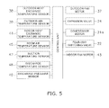
- FIG. 5 is a control block diagram of the air conditioning apparatus
- FIG. 6 is a flowchart of heating stop control
- FIG. 7 is a time chart of a compressor, an outdoor fan, an expansion valve, an indoor fan, and a four-way switching valve during the heating stop control (in a case where it is not an abnormal stop);
- FIG. 8 is an external perspective view of the outdoor heat exchanger in example modification 1.
- FIG. 1 is a schematic configuration diagram of an air conditioning apparatus 1 pertaining to the embodiment of the present invention.
- the air conditioning apparatus 1 is an apparatus that can cool and heat a room in a building, for example, by performing a vapor compression refrigeration cycle.
- the air conditioning apparatus 1 is mainly configured as a result of an outdoor unit 2 and an indoor unit 4 being interconnected.
- the outdoor unit 2 and the indoor unit 4 are interconnected by a liquid refrigerant connection pipe 5 and a gas refrigerant connection pipe 6 .
- a vapor compression refrigerant circuit 10 of the air conditioning apparatus 1 is configured as a result of the outdoor unit 2 and the indoor unit 4 being interconnected by the refrigerant connection pipes 5 and 6 .
- the indoor unit 4 is installed in a room and configures part of the refrigerant circuit 10 .
- the indoor unit 4 mainly has an indoor heat exchanger 41 .
- the indoor heat exchanger 41 is a heat exchanger which, during a cooling operation, functions as an evaporator of refrigerant to cool the room air and, during a heating operation, functions as a radiator of the refrigerant to heat the room air.
- the liquid side of the indoor heat exchanger 41 is connected to the liquid refrigerant connection pipe 5
- the gas side of the indoor heat exchanger 41 is connected to the gas refrigerant connection pipe 6 .
- the indoor heat exchanger 41 here is a heat exchanger that uses round tubes as heat transfer tubes. More specifically, the indoor heat exchanger 41 is a cross fin type fin-and-tube heat exchanger configured by heat transfer tubes comprising round tubes and numerous fins. For the round tubes serving as the heat transfer tubes, tubes having flow path holes with an inner diameter of about 3 to 20 mm are used.
- the indoor unit 4 has an indoor fan 42 for sucking room air into the indoor unit 4 , causing the room air to exchange heat with the refrigerant in the indoor heat exchanger 41 , and supplying the air to the room as supply air. That is, the indoor unit 4 has the indoor fan 42 as a fan that supplies, to the indoor heat exchanger 41 , room air serving as a heating source or a cooling source of the refrigerant flowing through the indoor heat exchanger 41 .
- a centrifugal fan or a multi-blade fan driven by an indoor fan motor 43 is used as the indoor fan 42 .
- an indoor heat exchange temperature sensor 44 that detects a temperature Trr of the refrigerant in the indoor heat exchanger 41 is disposed in the indoor heat exchanger 41 .
- a room air temperature sensor 45 that detects a temperature Tra of the room air sucked into the indoor unit 4 is disposed in the indoor unit 4 .
- the indoor unit 4 has an indoor-side control unit 46 that controls the actions of each part configuring the indoor unit 4 . Additionally, the indoor-side control unit 46 has a microcomputer and a memory disposed in order to control the indoor unit 4 , and the indoor-side control unit 46 can exchange control signals and so forth with a remote controller (not shown in the drawings) for individually operating the indoor unit 4 and can exchange control signals and so forth with the outdoor unit 2 via a transmission line 7 .
- a remote controller not shown in the drawings
- the outdoor unit 2 is installed outdoors and configures part of the refrigerant circuit 10 .
- the outdoor unit 2 mainly has a compressor 21 , a four-way switching valve 22 , an outdoor heat exchanger 23 , an expansion valve 24 , an accumulator 25 , a liquid-side stop valve 26 , and a gas-side stop valve 27 .
- the compressor 21 is a device that compresses low-pressure refrigerant in the refrigeration cycle to a high pressure.
- the compressor 21 has a closed structure in which a positive-displacement compression element such as rotary or scroll type (not shown in the drawings) is driven to rotate by a compressor motor 21 a controlled by an inverter.
- a suction pipe 31 is connected to the suction side of the compressor 21
- a discharge pipe 32 is connected to the discharge side of the compressor 21 .
- the suction pipe 31 is a refrigerant pipe that interconnects the suction side of the compressor 21 and a first port 22 a of the four-way switching valve 22 .
- the discharge pipe 32 is a refrigerant pipe that interconnects the discharge side of the compressor 21 and a second port 22 b of the four-way switching valve 22 .
- the four-way switching valve 22 is a switching valve for switching the direction of the flow of the refrigerant in the refrigerant circuit 10 .
- the four-way switching valve 22 performs switching to a cooling cycle state that causes the outdoor heat exchanger 23 to function as a radiator of the refrigerant that has been compressed in the compressor 21 and causes the indoor heat exchanger 41 to function as an evaporator of the refrigerant that has given off heat in the outdoor heat exchanger 23 . That is, during the cooling operation, the four-way switching valve 22 performs switching that places the second port 22 b and a third port 22 c in communication with one another and places the first port 22 a and a fourth port 22 d in communication with one another.
- the discharge side of the compressor 21 (here, the discharge pipe 32 ) and the gas side of the outdoor heat exchanger 23 (here, a first gas refrigerant pipe 33 ) become interconnected (see the solid lines of the four-way switching valve 22 in FIG. 1 ).
- the suction side of the compressor 21 (here, the suction pipe 31 ) and the gas refrigerant connection pipe 6 side (here, a second gas refrigerant pipe 34 ) become interconnected (see the solid lines of the four-way switching valve 22 in FIG. 1 ).
- the four-way switching valve 22 performs switching to a heating cycle state that causes the outdoor heat exchanger 23 to function as an evaporator of the refrigerant that has given off heat in the indoor heat exchanger 41 and causes the indoor heat exchanger 41 to function as a radiator of the refrigerant that has been compressed in the compressor 21 . That is, during the heating operation, the four-way switching valve 22 performs switching that places the second port 22 b and the fourth port 22 d in communication with one another and places the first port 22 a and the third port 22 c in communication with one another.
- the discharge side of the compressor 21 (here, the discharge pipe 32 ) and the gas refrigerant connection pipe 6 side (here, the second gas refrigerant pipe 34 ) become interconnected (see the dashed lines of the four-way switching valve 22 in FIG. 1 ).
- the suction side of the compressor 21 (here, the suction pipe 31 ) and the gas side of the outdoor heat exchanger 23 (here, the first gas refrigerant pipe 33 ) become interconnected (see the dashed lines of the four-way switching valve 22 in FIG. 1 ).
- the first gas refrigerant pipe 33 is a refrigerant pipe that interconnects the third port 22 c of the four-way switching valve 22 and the gas side of the outdoor heat exchanger 23 .
- the second gas refrigerant pipe 34 is a refrigerant pipe that interconnects the fourth port 22 d of the four-way switching valve 22 and the gas refrigerant connection pipe 6 side.
- the outdoor heat exchanger 23 is a heat exchanger which, during the cooling operation, functions as a radiator of the refrigerant using outdoor air as a cooling source and which, during the heating operation, functions as an evaporator of the refrigerant using outdoor air as a heating source.
- the liquid side of the outdoor heat exchanger 23 is connected to a liquid refrigerant pipe 35
- the gas side of the outdoor heat exchanger 23 is connected to the first gas refrigerant pipe 33 .
- the liquid refrigerant pipe 35 is a refrigerant pipe that interconnects the liquid side of the outdoor heat exchanger 23 and the liquid refrigerant connection pipe 5 side.
- That outdoor heat exchanger 23 is a heat exchanger that uses multi-hole flat tubes as heat transfer tubes. More specifically, as shown in FIG.
- the outdoor heat exchanger 23 is an insertion fin stacked heat exchanger mainly configured by heat transfer tubes 231 comprising multi-hole flat tubes and numerous insertion fins 232 .
- the heat transfer tubes 231 comprising multi-hole flat tubes are formed of aluminum or aluminum alloy and have upper and lower planar portions serving as heat transfer surfaces and numerous small refrigerant flow paths 231 a through which the refrigerant flows.
- refrigerant flow paths 231 a refrigerant flow paths having circular flow path holes with an inner diameter equal to or less than 1 mm or polygonal flow path holes having the same sectional area as this are used.
- the heat transfer tubes 231 are arranged in plural tiers spaced apart from one another in a state in which the planar portions face up and down, and both ends of each of the heat transfer tubes 231 are connected to headers 233 and 234 .
- the insertion fins 232 are fins made of aluminum or aluminum alloy and are in contact with the heat transfer tubes 231 .
- Plural cutouts 232 a that are long and narrow and extend in the horizontal direction are firmed in the insertion fins 232 so that the insertion fins 232 can be inserted into the plural tiers of heat transfer tubes 231 arranged between both of the headers 233 and 234 .
- the shape of the cutouts 232 a in these insertion fins 232 substantially matches the outer shape of the cross section of the heat transfer tubes 231 .
- the headers 233 and 234 have the function of the supporting the heat transfer tubes 231 , the function of guiding the refrigerant to the refrigerant flow paths 231 a in the heat transfer tubes 231 , and the function of collecting the refrigerant emerging from the refrigerant flow paths 231 a .
- the inside space of the header 233 is partitioned into two spaces by a partition plate 233 a .
- the inside space of the header 234 is partitioned into five spaces by partition plates 234 a , 234 b , 234 c , and 234 d .
- Refrigerant path connection pipes 235 and 236 , the first gas refrigerant pipe 33 , and the liquid refrigerant pipe 35 are, in addition to the heat transfer tubes 231 , connected to the inside spaces in these headers 233 and 234 . Additionally, in the cooling operation, high-pressure gas refrigerant in the refrigeration cycle that has been discharged from the compressor 21 flows into the space in the upper portion of the header 233 via the first gas refrigerant pipe 33 .
- the gas refrigerant that has flowed into the space in the upper portion of the header 233 is sent through the heat transfer tubes 231 to the upper three inside spaces of the five inside spaces of the header 234 , thereafter doubles back, and is sent to the space in the lower portion of the header 233 through the heat transfer tubes 231 disposed below.
- the refrigerant that was condensed when it passed through the heat transfer tubes 231 flows out to the liquid refrigerant pipe 35 from the space in the lower portion of the header 233 and is sent to the expansion valve 24 .
- the direction in which the refrigerant flows is the opposite of what it is during the cooling operation.
- the expansion valve 24 is a valve which, during the cooling operation, reduces the pressure of the high-pressure refrigerant in the refrigeration cycle that has given off heat in the outdoor heat exchanger 23 to a low pressure in the refrigeration cycle. Furthermore, the expansion valve 24 is a valve which, during the heating operation, reduces the pressure of the high-pressure refrigerant in the refrigeration cycle that has given off heat in the indoor heat exchanger 41 to a low pressure in the refrigeration cycle.
- the expansion valve 24 is disposed in the section of the liquid refrigerant pipe 35 near the liquid-side stop valve 26 .
- an electrically powered expansion valve is used as the expansion valve 24 .
- the accumulator 25 is a container that temporarily accumulates the low-pressure refrigerant sucked into the compressor 21 .
- the accumulator 25 is disposed in the suction pipe 31 .
- the liquid-side stop valve 26 and the gas-side stop valve 27 are valves disposed in openings connecting to outside devices and pipes (specifically, the liquid refrigerant connection pipe 5 and the gas refrigerant connection pipe 6 ).
- the liquid-side stop valve 26 is disposed on the end portion of the liquid refrigerant pipe 35 .
- the gas-side stop valve 27 is disposed on the end portion of the second gas refrigerant pipe 34 .
- the outdoor unit 2 has an outdoor fan 36 for sucking outdoor air into the outdoor unit causing the outdoor air to exchange heat with the refrigerant in the outdoor heat exchanger 23 , and expelling the air to the outside. That is, the outdoor unit 2 has an outdoor fan 36 as a fan that supplies, to the outdoor heat exchanger 23 , outdoor air serving as a cooling source or a heating source of the refrigerant flowing through the outdoor heat exchanger 23 .
- a propeller fan for example, driven by an outdoor fan motor 37 is used as the outdoor fan 36 .
- an outdoor heat exchange temperature sensor 38 that detects a temperature Tor of the refrigerant in the outdoor heat exchanger 23 is disposed in the outdoor heat exchanger 23 .
- An outdoor air temperature sensor 39 that detects a temperature Toa of the outdoor air sucked into the outdoor unit 2 is disposed in the outdoor unit 2 .
- a suction temperature sensor 47 that detects a temperature Ts of the low-pressure refrigerant in the refrigeration cycle that is sucked into the compressor 21 is disposed in the suction pipe 31 or the compressor 21 .
- a discharge temperature sensor 48 that detects a temperature Td of the high-pressure refrigerant in the refrigeration cycle that is discharged from the compressor 21 is disposed in the discharge pipe 32 or the compressor 21 .
- a discharge pressure sensor 49 that detects a pressure Pd of the high-pressure refrigerant in the refrigeration cycle that is discharged from the compressor 21 is disposed in the discharge pipe 32 or the compressor 21 .
- the outdoor unit 2 has an outdoor-side control unit 40 that controls the actions of each part configuring the outdoor unit 2 . Additionally, the outdoor-side control unit 40 has a microcomputer and a memory disposed in order to control the outdoor unit 2 , and the outdoor-side control unit 40 can exchange control signals and so forth with the indoor unit 4 via the transmission line 7 .
- the refrigerant connection pipes 5 and 6 are refrigerant pipes installed on site when installing the air conditioning apparatus 1 in an installation location such as a building, and pipes having various lengths and pipe diameters are used depending on installation conditions such as the installation location and the combination of the outdoor unit and the indoor unit.
- the refrigerant circuit 10 of the air conditioning apparatus 1 is configured as a result of the outdoor unit 2 , the indoor unit 4 , and the refrigerant connection pipes 5 and 6 being connected.
- the air conditioning apparatus 1 switches the four-way switching valve 22 to the cooling cycle state to thereby circulate the refrigerant in the order of the compressor 21 , the outdoor heat exchanger 23 , the expansion valve 24 , and the indoor heat exchanger 41 , drives the outdoor fan 36 , and performs the cooling operation.
- the air conditioning apparatus 1 switches the four-way switching valve 22 to the heating cycle state to thereby circulate the refrigerant in the order of the compressor 21 , the indoor heat exchanger 41 , the expansion valve 24 , and the outdoor heat exchanger 23 , drives the outdoor fan 36 , and performs the heating operation.
- the air conditioning apparatus 1 is given a configuration that uses the outdoor air or the room air as a heating source and a cooling source for the outdoor heat exchanger 23 and the indoor heat exchanger 41 , but the air conditioning apparatus 1 is not limited to this and may also have a configuration that uses water as a heating source and a cooling source.
- the air conditioning apparatus 1 can control the various devices in the outdoor unit 2 and the indoor unit 4 using a control unit 8 configured from the indoor-side control unit 46 and the outdoor-side control unit 40 . That is, a control unit 8 that controls the operations of the entire air conditioning apparatus 1 including the cooling operation and the heating operation is configured by the indoor-side control unit 46 , the outdoor-side control unit 40 , and the transmission line 7 that interconnects the indoor-side control unit 46 and the outdoor-side control unit 40 .
- control unit 8 is connected in such a way that it can receive detection signals of the various sensors 38 , 39 , 44 , 45 , and 47 to 49 and is connected in such a way that it can control the various devices and valves 21 , 22 , 24 , 37 , and 43 on the basis of these detection signals.
- the air conditioning apparatus 1 can perform the cooling operation and the heating operation as basic actions. Furthermore, during the heating operation, the air conditioning apparatus 1 can also perform a defrost operation for melting frost sticking to the outdoor heat exchanger 23 .
- the four-way switching valve 22 is switched to the heating cycle state (the state indicated by the dashed lines in FIG. 1 ).
- the low-pressure gas refrigerant in the refrigeration cycle is sucked into the compressor 21 , is compressed to a high pressure in the refrigeration cycle, and is thereafter discharged.
- the high-pressure gas refrigerant that has been discharged from the compressor 21 is sent through the four-way switching valve 22 , the gas-side stop valve 27 , and the gas refrigerant connection pipe 6 to the indoor heat exchanger 41 .
- the high-pressure gas refrigerant that has been sent to the indoor heat exchanger 41 exchanges heat with the room air supplied as a cooling source by the indoor fan 42 , gives off heat, and becomes high-pressure liquid refrigerant in the indoor heat exchanger 41 . Because of this, the room air is heated and is thereafter supplied to the room, whereby heating of the room is performed.
- the high-pressure liquid refrigerant that has given off heat in the indoor heat exchanger 41 is sent through the liquid refrigerant connection pipe 5 and the liquid-side stop valve 26 to the expansion valve 24 .
- the high-pressure liquid refrigerant that has been sent to the expansion valve 24 has its pressure reduced by the expansion valve 24 to a low pressure in the refrigeration cycle and becomes low-pressure refrigerant in a gas-liquid two-phase state.
- the low-pressure refrigerant in the gas-liquid two-phase state whose pressure has been reduced by the expansion valve 24 is sent to the outdoor heat exchanger 23 .
- the low-pressure refrigerant in the gas-liquid two-phase state that has been sent to the outdoor heat exchanger 23 exchanges heat with the room air supplied as a heating source by the outdoor fan 36 , evaporates, and becomes low-pressure gas refrigerant in the outdoor heat exchanger 23 .
- the low-pressure gas refrigerant that has evaporated in the outdoor heat exchanger 23 travels through the four-way switching valve 22 and is sucked back into the compressor 21 .
- the four-way switching valve 22 is switched to the cooling cycle state (the state indicated by the solid lines in FIG. 1 ).
- the low-pressure gas refrigerant in the refrigeration cycle is sucked into the compressor 21 , is compressed to a high pressure in the refrigeration cycle, and is thereafter discharged.
- the high-pressure gas refrigerant that has been discharged from the compressor 21 is sent through the four-way switching valve 22 to the outdoor heat exchanger 23 .
- the high-pressure gas refrigerant that has been sent to the outdoor heat exchanger 23 exchanges heat with the outdoor air supplied as a cooling source by the outdoor fan 36 , gives off heat, and becomes high-pressure liquid refrigerant in the outdoor heat exchanger 23 .
- the high-pressure liquid refrigerant that has given off heat in the outdoor heat exchanger 23 is sent to the expansion valve 24 .
- the high-pressure liquid refrigerant that has been sent to the expansion valve 24 has its pressure reduced by the expansion valve 24 to a low pressure in the refrigeration cycle and becomes low-pressure refrigerant in a gas-liquid two-phase state.
- the low-pressure refrigerant in the gas-liquid two-phase state whose pressure has been reduced by the expansion valve 24 is sent through the liquid-side stop valve 26 and the liquid refrigerant connection pipe 5 to the indoor heat exchanger 41 .
- the low-pressure refrigerant in the gas-liquid two-phase state that has been sent to the indoor heat exchanger 41 exchanges heat with the room air supplied as a heating source by the indoor fan 42 , evaporates, and becomes low-pressure gas refrigerant in the indoor heat exchanger 41 . Because of this, the room air is cooled and is thereafter supplied to the room, whereby cooling of the room is performed.
- the low-pressure gas refrigerant that has evaporated in the indoor heat exchanger 41 travels through the gas refrigerant connection pipe 6 , the gas-side stop valve 27 , and the four-way switching valve 22 and is sucked back into the compressor 21 .
- the air conditioning apparatus 1 performs a defrost operation that melts the frost sticking to the outdoor heat exchanger 23 .
- the four-way switching valve 22 is switched to the cooling cycle state (the state indicated by the solid lines in FIG. 1 ) to thereby cause the outdoor heat exchanger 23 to function as a radiator of the refrigerant. Because of this, the frost sticking to the outdoor heat exchanger 23 can be melted.
- the flow of the refrigerant in the refrigerant circuit 10 during the defrost operation is the same as what it is during the cooling operation, an description thereof will be omitted here.
- the air conditioning apparatus 1 When the air conditioning apparatus 1 stops the above-described heating operation as a result of the thermo-off or receiving a command from the remote controller (not shown in the drawings), the air conditioning apparatus 1 maintains the four-way switching valve 22 in the heating cycle state, stops the compressor 21 , and equalizes the pressure in the refrigerant circuit 10 .
- liquid refrigerant that has collected in the multi-hole flat tubes serving as the heat transfer tubes 231 of the outdoor heat exchanger 23 ends up being pushed out to the suction side of the compressor 21 by the flow of the refrigerant in the refrigerant circuit 10 during the pressure equalization. Because of this, there is the concern that when the heating operation is resumed, the compressor 21 will suck in the liquid refrigerant.
- the outdoor heat exchanger functions as an evaporator of the refrigerant during the heating operation. For this reason, when the air conditioning apparatus stops the heating operation, liquid refrigerant collects in the heat transfer tubes of the outdoor heat exchanger regardless of whether round tubes or multi-hole flat tubes are used as the heat transfer tubes of the outdoor heat exchanger.
- the numerous small refrigerant flow paths 231 a formed in the multi-hole flat tubes end up being almost completely filled with liquid refrigerant, and almost no spaces through which gas refrigerant flows are formed.
- the air conditioning apparatus 1 in heating stop control performed when the heating operation is stopped, in consideration of differences in the behavior of the refrigerant during the pressure equalization due to the type of the heat transfer tubes 231 , when stopping the heating operation, the air conditioning apparatus 1 is configured to perform pressure equalization control that switches the four-way switching valve 22 from the heating cycle state to the cooling cycle state and thereafter stops the compressor 21 .
- FIG. 6 is a flowchart of the heating stop control.
- FIG. 7 is a time chart of the compressor 21 , the outdoor fan 36 , the expansion valve 24 , the indoor fan 42 , and the four-way switching valve 22 during the heating stop control (in a case where it is not an abnormal stop).
- the heating stop control described below is, like the above-described basic actions, performed by the control unit 8 .
- step ST 4 when stopping the heating operation, the air conditioning apparatus 1 switches the four-way switching valve 22 from the heating cycle state to the cooling cycle state, stops the compressor 21 , and equalizes the pressure in the refrigerant circuit 10 . Because of this, because of the four-way switching valve 22 that has been switched to the cooling cycle state, a flow in which the refrigerant flows into the outdoor heat exchanger 23 from the expansion valve 24 during the pressure equalization is no longer generated in the refrigerant circuit 10 .
- the air conditioning apparatus 1 employs as the outdoor heat exchanger 23 a heat exchanger that uses multi-hole flat tubes as the heat transfer tubes 231 , Furthermore, in the present embodiment, the air conditioning apparatus 1 employs a configuration having the accumulator 25 , so even if liquid refrigerant were to be pushed out to the suction side of the compressor 21 from the outdoor heat exchanger 23 during the pressure equalization of the refrigerant circuit 10 when stopping the heating operation, this liquid refrigerant can be accumulated in the accumulator 25 .
- the air conditioning apparatus 1 is configured to perform the above-described pressure equalization control despite the fact that it has a configuration having the accumulator 25 , so the liquid refrigerant accumulating in the accumulator 25 can be kept from overflowing out to the suction side of the compressor 21 when the heating operation is resumed.
- the pressure equalization of the refrigerant circuit 10 be performed quickly during the pressure equalization control, so the opening degree of the expansion valve 24 is set to a pressure equalization opening degree Xeq, which is a larger opening degree than during accumulator refrigerant discharge control and four-way switching noise reduction control described later.
- liquid refrigerant can be kept from being pushed out to the suction side of the compressor 21 from the outdoor heat exchanger 23 when the air conditioning apparatus 1 stops the heating operation.
- liquid refrigerant will no longer collect in the outdoor heat exchanger 23 .
- the air conditioning apparatus 1 is configured to perform outdoor heat exchanger refrigerant discharge control that switches the four-way switching valve 22 to the cooling cycle state and thereafter continues the operation of the compressor 21 . Specifically, the air conditioning apparatus 1 switches the four-way switching valve 22 to the cooling cycle state, thereafter continues the operation of the compressor 21 , and stops the compressor 21 after about 40 to 80 seconds have elapsed (see time t 3 in FIG. 6 ).
- the timing when the air conditioning apparatus 1 stops the compressor 21 is delayed compared to the timing when the air conditioning apparatus 1 switches the four-way switching valve 22 to the cooling cycle state, and a flow of refrigerant that circulates in the same way as during the cooling operation can be generated in the refrigerant circuit 10 before the air conditioning apparatus 1 stops the compressor 21 .
- liquid refrigerant that has collected in the heat transfer tubes 231 comprising multi-hole flat tubes of the outdoor heat exchanger during the heating operation can be discharged through the expansion valve 24 to the indoor heat exchanger 41 side before the air conditioning apparatus 1 stops the compressor 21 .
- the outdoor heat exchanger refrigerant discharge control it is preferred that the discharge of the liquid refrigerant that has accumulated in the outdoor heat exchanger 23 be accelerated, so the operating frequency of the compressor 21 is set to an outdoor heat exchanger refrigerant discharge control frequency fex, which is a larger operating frequency than during the accumulator refrigerant discharge control and the four-way switching noise reduction control described later.
- the above-described outdoor heat exchanger refrigerant discharge control generates in the refrigerant circuit 10 a flow of refrigerant that circulates in the same way as during the cooling operation, so the indoor heat exchanger 41 functions as an evaporator of the refrigerant.
- the indoor heat exchanger 41 functions as an evaporator of the refrigerant.
- the air conditioning apparatus 1 is configured to perform control that stops the indoor fan 42 .
- the air conditioning apparatus 1 performs an operation that switches the four-way switching valve 22 from the heating cycle state to the cooling cycle state and thereafter stops the indoor fan 42 . Because of this, at the time of the outdoor heat exchanger refrigerant discharge control, it can be ensured that cool air is not blown into the room and it can be made difficult for a cool sensation to be imparted to the people in the room. However, in a case where it is not necessary to take into consideration a cool sensation being imparted to the people in the room, the indoor fan 42 does not have to be stopped at the time of the outdoor heat exchanger refrigerant discharge control.
- the above-described outdoor heat exchanger refrigerant discharge control generates in the refrigerant circuit 10 a flow of refrigerant that circulates in the same way as during the cooling operation, so the outdoor heat exchanger 23 functions as a condenser of the refrigerant.
- the air conditioning apparatus 1 is configured to perform control that stops the outdoor fan 36 at the time of the outdoor heat exchanger refrigerant discharge control.
- the air conditioning apparatus 1 performs an operation that switches the four-way switching valve 22 from the heating cycle state to the cooling cycle state and thereafter stops the outdoor fan 36 . Because of this, at the time of the outdoor heat exchanger refrigerant discharge control, liquid refrigerant can be kept from being generated in the outdoor heat exchanger 23 and the discharge of the liquid refrigerant that has accumulated in the outdoor heat exchanger 23 through the expansion valve 24 to the indoor heat exchanger 41 side can be accelerated. However, in a case where liquid refrigerant that has accumulated in the outdoor heat exchanger 23 cannot be sufficiently discharged even if the outdoor fan 36 is not stopped, the outdoor fan 36 does not have to be stopped at the time of the outdoor heat exchanger refrigerant discharge control.
- the air conditioning apparatus 1 is configured to perform the pressure equalization control of step ST 4 despite the fact that it has a configuration having the accumulator 25 . For this reason, when the heating operation is resumed, liquid refrigerant accumulating in the accumulator 25 can generally be kept from overflowing out to the suction side of the compressor 21 . Yet in a case where, when the air conditioning apparatus 1 stops the heating operation, the quantity of liquid refrigerant accumulating in the accumulator 25 is extremely large, some concern remains that even if the pressure equalization control of step ST 4 is performed, the liquid refrigerant accumulating in the accumulator 25 will not be able to be kept from flowing out to the suction side of the compressor 21 when the heating operation is resumed.
- the air conditioning apparatus 1 is configured to not only perform the pressure equalization control of step ST 4 but also perform accumulator refrigerant discharge control (step ST 1 ) that reduces the opening degree of the expansion valve 24 before the pressure equalization control. Specifically, the air conditioning apparatus 1 operates the compressor 21 in a state in which the opening degree of the expansion valve 24 has been reduced for about 120 to 240 seconds (see time t 1 in FIG. 7 ) after receiving a command to stop the heating operation.
- the opening degree of the expansion valve 24 be set to an accumulator refrigerant discharge opening degree Xac, which is smaller than the opening degree before starting the accumulator refrigerant discharge control and the pressure equalization opening degree Xeq.
- the accumulator refrigerant discharge opening degree Xac is set to an opening degree that is equal to or less than 0.2 times the pressure equalization opening degree Xeq.
- the operating frequency of the compressor 21 be set to an accumulator refrigerant discharge frequency fax, which is smaller than the outdoor heat exchanger refrigerant discharge frequency fex.
- the accumulator refrigerant discharge frequency fac is set to an operating frequency that is about 0.5 to 0.8 times the outdoor heat exchanger refrigerant discharge frequency fex.
- the accumulator refrigerant discharge control does not have to be performed in a case where the air conditioning apparatus 1 has a configuration not having the accumulator 25 or a case where liquid refrigerant accumulating in the accumulator 25 can be kept from overflowing by just performing the pressure equalization control.
- the air conditioning apparatus 1 moves to the processing of steps ST 2 and ST 3 .
- Step ST 2 and Step ST 3 >
- the air conditioning apparatus 1 is configured to perform, before the pressure equalization control of ST 4 , four-way switching noise reduction control that reduces the operating frequency of the compressor 21 (step ST 3 ).
- the air conditioning apparatus 1 performs the accumulator refrigerant discharge control of step ST 1 , so the air conditioning apparatus 1 performs an operation that reduces the operating frequency of the compressor 21 for about 60 to 120 seconds (see time t 2 in FIG. 7 ) between the accumulator refrigerant discharge control and the pressure equalization control. Because of this, when the air conditioning apparatus 1 switches the four-way switching valve 22 from the heating cycle state to the cooling cycle state, the high-low pressure difference between the four ports 22 a to 22 d of the four-way switching valve 22 can be reduced and the switching noise made by the four-way switching valve 22 can be reduced.
- the operating frequency of the compressor 21 be set to a four-way switching noise reduction frequency fv that is smaller than the operating frequency (in the present embodiment, the accumulator refrigerant discharge frequency fac) before starting the four-way switching noise reduction control.
- the four-way switching noise reduction frequency fv is set to an operating frequency that is equal to or less than 0.5 times the accumulator refrigerant discharge frequency fac.
- the opening degree of the expansion valve 24 is set to a four-way switching noise reduction opening degree Xv that is equal to or smaller than the accumulator refrigerant discharge opening degree Xac.
- the four-way switching noise reduction control does not have to be performed.
- the object of the four-way switching noise reduction control is to reduce the switching noise made during the switching operation of the four-way switching valve 22 .
- the air conditioning apparatus 1 when the air conditioning apparatus 1 stops the heating operation as a result of the thermo-off or receiving a command from the remote controller (not shown in the drawings), it is preferred that the air conditioning apparatus 1 perform the four-way switching noise reduction control, but in the case of an abnormal stop caused by a device abnormality, for example, it is preferred that device protection be given priority over reducing the switching noise made by the four-way switching valve 22 and that the air conditioning apparatus 1 be stopped quickly. Therefore, here, the air conditioning apparatus 1 is configured to not perform the four-way switching noise reduction control in a case where the stopping of the heating operation is an abnormal stop (step ST 2 ).
- the air conditioning apparatus 1 when stopping the heating operation as a result of the thermo-off or receiving a command from the remote controller (not shown in the drawings), the air conditioning apparatus 1 is configured to perform the pressure equalization control after performing the four-way switching noise reduction control, and in the case of an abnormal stop, the air conditioning apparatus 1 is configured to perform the pressure equalization control without performing the four-way switching noise reduction control. Because of this, the pressure equalization control can be performed white giving appropriate consideration to both the switching noise made during the switching operation of the four-way switching valve 22 and device protection.
- the air conditioning apparatus 1 employs as the outdoor heat exchanger 23 an insertion fin stacked heat exchanger configured by the plural heat transfer tubes 231 comprising multi-hole flat tubes and the numerous insertion fins 232 (see FIG. 2 to FIG. 4 ), but the air conditioning apparatus 1 is not limited to this.
- the air conditioning apparatus 1 may also employ as the outdoor heat exchanger 23 a corrugated fin stacked heat exchanger configured by the plural, heat transfer tubes 231 comprising multi-hole flat tubes and numerous corrugated fins 237 .
- the corrugated fins 237 are fins made of aluminum or aluminum alloy bent in a corrugated shape.
- the corrugated fins 237 are disposed in air flow spaces sandwiched by the vertically adjacent heat transfer tubes 231 , and the grooves and ridges of the corrugated fins 237 are in contact with the planar portions of the heat transfer tubes 231 .
- the air conditioning apparatus 1 is configured to perform the accumulator refrigerant discharge control of step ST 1 for just the time t 1 , but the air conditioning apparatus 1 is not limited to this.
- the air conditioning apparatus 1 may also be configured to end the accumulator refrigerant discharge control and move to the processing of steps ST 2 to ST 4 even before the time t 1 elapses. Because of this, a contribution can be made to shorten the amount of time of the accumulator refrigerant discharge control.
- the degree of superheat SH of the refrigerant in the suction side of the compressor 21 can be obtained, for example, by subtracting the temperature Tor of the refrigerant in the outdoor heat exchanger 23 from the temperature Ts of the low-pressure refrigerant sucked into the compressor 21 .
- the air conditioning apparatus 1 fixes the opening degree of the expansion valve 24 during the accumulator refrigerant discharge control of step ST 1 at the accumulator refrigerant discharge opening degree Xac, but the air conditioning apparatus 1 is not limited to this.
- the air conditioning apparatus 1 may also be configured to vary the accumulator refrigerant discharge opening degree Xac by controlling the opening degree of the expansion valve 24 in such a way that the degree of superheat SH of the refrigerant in the suction side of the compressor 21 becomes constant at a predetermined accumulator refrigerant discharge control degree of superheat SHacc. Because of this, a contribution can be made to shorten the amount of time of the accumulator refrigerant discharge control.
- the air conditioning apparatus 1 is configured to perform the four-way switching noise reduction control of step ST 3 for just the time t 2 , but the air conditioning apparatus 1 is not limited to this.
- the air conditioning apparatus 1 may also be configured to end the four-way switching noise reduction control and move to the processing of step ST 4 even before the time t 2 elapses.
- the air conditioning apparatus 1 may also be configured to end the four-way switching noise reduction control and move to the processing of step ST 4 even before the time t 2 elapses.
- the air conditioning apparatus 1 fixes the operating frequency of the compressor 21 at the four-way switching noise reduction frequency fv, but the air conditioning apparatus 1 is not limited to this.
- the air conditioning apparatus 1 may also be configured to reduce the four-way switching noise reduction frequency fv in stages during the time t 2 .
- the air conditioning apparatus 1 fixes the opening degree of the expansion valve 24 at the four-way switching noise reduction opening degree Xv, but the air conditioning apparatus 1 may also be configured to increase the opening degree of the expansion valve 24 in stages during the time t 2 .
- the air conditioning apparatus 1 may also be configured to make the air volume of the outdoor fan 36 smaller than the air volume during the accumulator refrigerant discharge control of step ST 1 . Because of this, the four-way switching noise reduction control can be stably performed.
- the air conditioning apparatus 1 when a command to stop the heating operation is given as a result of the thermo-off or by the remote controller (not shown in the drawings) during the heating operation, the air conditioning apparatus 1 is configured to perform the pressure equalization control of step ST 4 ; that is, when stopping the heating operation, the air conditioning apparatus 1 is configured to switch the four-way switching valve 22 from the heating cycle state to the cooling cycle state, stop the compressor 21 , and equalize the pressure in the refrigerant circuit 10 .
- the four-way switching valve 22 becomes switched to the cooling cycle state before the air conditioning apparatus 1 performs the pressure equalization control of step ST 4 .
- the air conditioning apparatus 1 may also be configured to stop the heating operation without performing the pressure equalization control of step ST 4 .
- a predetermined defrost operation completion condition e.g., a predetermined amount of time elapses, or the temperature of the refrigerant in the outdoor heat exchanger 23 rises to a predetermined temperature
- step ST 4 by stopping the heating operation without performing the pressure equalization control of step ST 4 in a case where a command to stop the heating operation has been given by the remote controller not shown in the drawings) during the defrost operation, the processing for stopping the heating operation can be completed in a short amount of time.
- the present invention is widely applicable to air conditioning apparatus that use a four-way switching valve to switch between and perform a cooling operation and a heating operation.
Landscapes
- Engineering & Computer Science (AREA)
- Mechanical Engineering (AREA)
- General Engineering & Computer Science (AREA)
- Physics & Mathematics (AREA)
- Thermal Sciences (AREA)
- Chemical & Material Sciences (AREA)
- Combustion & Propulsion (AREA)
- Compression-Type Refrigeration Machines With Reversible Cycles (AREA)
- Air Conditioning Control Device (AREA)
- Other Air-Conditioning Systems (AREA)
Applications Claiming Priority (3)
| Application Number | Priority Date | Filing Date | Title |
|---|---|---|---|
| JP2012088668A JP5413480B2 (ja) | 2012-04-09 | 2012-04-09 | 空気調和装置 |
| JP2012-088668 | 2012-04-09 | ||
| PCT/JP2013/059924 WO2013153983A1 (fr) | 2012-04-09 | 2013-04-01 | Dispositif de climatisation |
Publications (2)
| Publication Number | Publication Date |
|---|---|
| US20150059377A1 US20150059377A1 (en) | 2015-03-05 |
| US9488399B2 true US9488399B2 (en) | 2016-11-08 |
Family
ID=49327551
Family Applications (1)
| Application Number | Title | Priority Date | Filing Date |
|---|---|---|---|
| US14/390,776 Active US9488399B2 (en) | 2012-04-09 | 2013-04-01 | Air conditioning apparatus |
Country Status (8)
| Country | Link |
|---|---|
| US (1) | US9488399B2 (fr) |
| EP (1) | EP2851633B1 (fr) |
| JP (1) | JP5413480B2 (fr) |
| KR (1) | KR101510609B1 (fr) |
| CN (1) | CN104204690B (fr) |
| AU (1) | AU2013247864B2 (fr) |
| BR (1) | BR112014024733B1 (fr) |
| WO (1) | WO2013153983A1 (fr) |
Cited By (4)
| Publication number | Priority date | Publication date | Assignee | Title |
|---|---|---|---|---|
| US20180340714A1 (en) * | 2017-05-26 | 2018-11-29 | Hitachi-Johnson Controls Air Conditioning, Inc. | Air conditioner |
| US20190275865A1 (en) * | 2016-11-14 | 2019-09-12 | Gree Electric Appliances, Inc. Of Zhuhai | Control method and system for air-conditioner water chilling units and air conditioning system |
| US11300339B2 (en) | 2018-04-05 | 2022-04-12 | Carrier Corporation | Method for optimizing pressure equalization in refrigeration equipment |
| US11441827B2 (en) | 2018-02-27 | 2022-09-13 | Carrier Corporation | Refrigerant leak detection system and method |
Families Citing this family (11)
| Publication number | Priority date | Publication date | Assignee | Title |
|---|---|---|---|---|
| AU2010225946B2 (en) * | 2009-03-19 | 2013-03-07 | Daikin Industries, Ltd. | Air conditioning apparatus |
| JP5842970B2 (ja) * | 2013-10-29 | 2016-01-13 | ダイキン工業株式会社 | 空気調和装置 |
| US20170016659A1 (en) * | 2015-07-14 | 2017-01-19 | Nortek Global Hvac Llc | Refrigerant charge and control method for heat pump systems |
| DK3332181T3 (da) | 2015-08-03 | 2021-10-25 | Carrier Corp | Kølesystem og driftsfremgangsmåde |
| JP6123853B2 (ja) * | 2015-08-18 | 2017-05-10 | ダイキン工業株式会社 | 空調機 |
| WO2019003268A1 (fr) * | 2017-06-26 | 2019-01-03 | 三菱電機株式会社 | Dispositif utilisant une pompe à chaleur |
| CN109556232B (zh) * | 2018-10-23 | 2020-02-04 | 珠海格力电器股份有限公司 | 四通阀异常检测方法、装置及空调机组 |
| JP2021025670A (ja) * | 2019-07-31 | 2021-02-22 | ダイキン工業株式会社 | 冷媒サイクル装置 |
| CN110466314A (zh) * | 2019-09-10 | 2019-11-19 | 薛炎 | 一种采用插片式微通道换热器的汽车热泵空调 |
| KR102868085B1 (ko) * | 2022-10-25 | 2025-10-01 | 엘지전자 주식회사 | 공기조화기 |
| CN116481146A (zh) * | 2023-04-14 | 2023-07-25 | 青岛海尔空调器有限总公司 | 空调的高压压力保护方法、保护装置和空调 |
Citations (25)
| Publication number | Priority date | Publication date | Assignee | Title |
|---|---|---|---|---|
| US4402190A (en) * | 1982-05-11 | 1983-09-06 | Reid Samuel I | Apparatus and method for heating and chilling concrete batch water |
| US4638643A (en) * | 1984-08-22 | 1987-01-27 | Hitachi, Ltd. | Control system for compressor motor used with air-conditioning unit |
| US5263333A (en) * | 1990-11-02 | 1993-11-23 | Kabushiki Kaisha Toshiba | Multi-type air conditioner system with optimum control for gaseous flow adjustment valve and liquid expansion valve |
| US5623834A (en) * | 1995-05-03 | 1997-04-29 | Copeland Corporation | Diagnostics for a heating and cooling system |
| US5970732A (en) * | 1997-04-23 | 1999-10-26 | Menin; Boris | Beverage cooling system |
| US6125885A (en) * | 1997-11-05 | 2000-10-03 | Kabushiki Kaisha Saginomiya Seisakusho | Rotary channel-selector valve |
| US6266968B1 (en) * | 2000-07-14 | 2001-07-31 | Robert Walter Redlich | Multiple evaporator refrigerator with expansion valve |
| US6508072B1 (en) * | 1998-10-26 | 2003-01-21 | Toshiba Carrier Corporation | Air conditioner outdoor unit drive control unit |
| US20030233838A1 (en) * | 2002-06-19 | 2003-12-25 | Lg Electronics Inc. | Air conditioning system with two compressors and method for operating the same |
| US20040103676A1 (en) * | 2002-11-22 | 2004-06-03 | Lg Electronics Inc. | Method for controlling cooling/heating of heat pump system |
| US20040107727A1 (en) * | 2002-12-04 | 2004-06-10 | Samsung Electronics Co., Ltd. | Time division multi-cycle type cooling apparatus and method for controlling the same |
| CN1786621A (zh) | 2004-12-07 | 2006-06-14 | 童夏民 | 低压差循环热泵空调机组 |
| US20060179855A1 (en) * | 2005-02-16 | 2006-08-17 | Carrier Corporation | Prevention of flooded starts in heat pumps |
| US20060218947A1 (en) | 2005-04-04 | 2006-10-05 | Carrier Corporation | Prevention of compressor unpowered reverse rotation in heat pump units |
| US20070167127A1 (en) * | 2006-01-17 | 2007-07-19 | Wiley Robby D | Ventilation air distribution box |
| CN101086375A (zh) | 2006-06-07 | 2007-12-12 | 乐金电子(天津)电器有限公司 | 空调器换向阀的控制方法 |
| US20080083236A1 (en) | 2006-10-10 | 2008-04-10 | Daewoo Electronics Corporation | Method for controlling stop operation of air conditioner |
| JP2009210139A (ja) | 2008-02-29 | 2009-09-17 | Mitsubishi Heavy Ind Ltd | マルチ型空気調和機 |
| US20090229285A1 (en) * | 2008-03-13 | 2009-09-17 | Aisin Seiki Kabushiki Kaisha | Air conditioning system and accumulator thereof |
| US20090320507A1 (en) * | 2006-07-10 | 2009-12-31 | Daikin Industries, Ltd. | Air conditioner control device |
| US20100101256A1 (en) * | 2007-01-23 | 2010-04-29 | Satoshi Kawano | Air conditioner |
| US20110079032A1 (en) * | 2008-07-09 | 2011-04-07 | Taras Michael F | Heat pump with microchannel heat exchangers as both outdoor and reheat exchangers |
| JP2011080649A (ja) | 2009-10-05 | 2011-04-21 | Daikin Industries Ltd | 空気調和装置 |
| US20110192183A1 (en) * | 2010-02-08 | 2011-08-11 | Ha Doyong | Refrigerant system |
| WO2012014769A1 (fr) | 2010-07-30 | 2012-02-02 | ダイキン工業株式会社 | Procédé de pliage pour échangeur de chaleur et échangeur de chaleur |
Family Cites Families (8)
| Publication number | Priority date | Publication date | Assignee | Title |
|---|---|---|---|---|
| JPH0752046B2 (ja) * | 1989-11-10 | 1995-06-05 | ダイキン工業株式会社 | 空気調和装置の運転制御装置 |
| JP3783153B2 (ja) * | 2000-05-19 | 2006-06-07 | 株式会社日立製作所 | 空気調和機 |
| JP3744774B2 (ja) * | 2000-06-12 | 2006-02-15 | 三洋電機株式会社 | ヒートポンプ式空気調和機 |
| CN101782305B (zh) * | 2009-01-15 | 2013-03-06 | 珠海格力电器股份有限公司 | 热泵型空气调节装置及其除霜方法 |
| JP5583533B2 (ja) | 2009-09-28 | 2014-09-03 | 日立オートモティブシステムズ株式会社 | ディスクブレーキ |
| CN102087056A (zh) * | 2009-12-04 | 2011-06-08 | 清水泰雅 | 提高热泵性能参数的装置 |
| JP5414811B2 (ja) * | 2010-01-19 | 2014-02-12 | 三菱電機株式会社 | 容積型膨張機及びこの容積型膨張機を用いた冷凍サイクル装置 |
| CN202057109U (zh) * | 2011-04-12 | 2011-11-30 | 广东机电职业技术学院 | 一种平行流冷暖空调器 |
-
2012
- 2012-04-09 JP JP2012088668A patent/JP5413480B2/ja active Active
-
2013
- 2013-04-01 EP EP13776366.0A patent/EP2851633B1/fr active Active
- 2013-04-01 US US14/390,776 patent/US9488399B2/en active Active
- 2013-04-01 WO PCT/JP2013/059924 patent/WO2013153983A1/fr not_active Ceased
- 2013-04-01 AU AU2013247864A patent/AU2013247864B2/en active Active
- 2013-04-01 BR BR112014024733-1A patent/BR112014024733B1/pt active IP Right Grant
- 2013-04-01 KR KR1020147031118A patent/KR101510609B1/ko active Active
- 2013-04-01 CN CN201380018888.5A patent/CN104204690B/zh active Active
Patent Citations (25)
| Publication number | Priority date | Publication date | Assignee | Title |
|---|---|---|---|---|
| US4402190A (en) * | 1982-05-11 | 1983-09-06 | Reid Samuel I | Apparatus and method for heating and chilling concrete batch water |
| US4638643A (en) * | 1984-08-22 | 1987-01-27 | Hitachi, Ltd. | Control system for compressor motor used with air-conditioning unit |
| US5263333A (en) * | 1990-11-02 | 1993-11-23 | Kabushiki Kaisha Toshiba | Multi-type air conditioner system with optimum control for gaseous flow adjustment valve and liquid expansion valve |
| US5623834A (en) * | 1995-05-03 | 1997-04-29 | Copeland Corporation | Diagnostics for a heating and cooling system |
| US5970732A (en) * | 1997-04-23 | 1999-10-26 | Menin; Boris | Beverage cooling system |
| US6125885A (en) * | 1997-11-05 | 2000-10-03 | Kabushiki Kaisha Saginomiya Seisakusho | Rotary channel-selector valve |
| US6508072B1 (en) * | 1998-10-26 | 2003-01-21 | Toshiba Carrier Corporation | Air conditioner outdoor unit drive control unit |
| US6266968B1 (en) * | 2000-07-14 | 2001-07-31 | Robert Walter Redlich | Multiple evaporator refrigerator with expansion valve |
| US20030233838A1 (en) * | 2002-06-19 | 2003-12-25 | Lg Electronics Inc. | Air conditioning system with two compressors and method for operating the same |
| US20040103676A1 (en) * | 2002-11-22 | 2004-06-03 | Lg Electronics Inc. | Method for controlling cooling/heating of heat pump system |
| US20040107727A1 (en) * | 2002-12-04 | 2004-06-10 | Samsung Electronics Co., Ltd. | Time division multi-cycle type cooling apparatus and method for controlling the same |
| CN1786621A (zh) | 2004-12-07 | 2006-06-14 | 童夏民 | 低压差循环热泵空调机组 |
| US20060179855A1 (en) * | 2005-02-16 | 2006-08-17 | Carrier Corporation | Prevention of flooded starts in heat pumps |
| US20060218947A1 (en) | 2005-04-04 | 2006-10-05 | Carrier Corporation | Prevention of compressor unpowered reverse rotation in heat pump units |
| US20070167127A1 (en) * | 2006-01-17 | 2007-07-19 | Wiley Robby D | Ventilation air distribution box |
| CN101086375A (zh) | 2006-06-07 | 2007-12-12 | 乐金电子(天津)电器有限公司 | 空调器换向阀的控制方法 |
| US20090320507A1 (en) * | 2006-07-10 | 2009-12-31 | Daikin Industries, Ltd. | Air conditioner control device |
| US20080083236A1 (en) | 2006-10-10 | 2008-04-10 | Daewoo Electronics Corporation | Method for controlling stop operation of air conditioner |
| US20100101256A1 (en) * | 2007-01-23 | 2010-04-29 | Satoshi Kawano | Air conditioner |
| JP2009210139A (ja) | 2008-02-29 | 2009-09-17 | Mitsubishi Heavy Ind Ltd | マルチ型空気調和機 |
| US20090229285A1 (en) * | 2008-03-13 | 2009-09-17 | Aisin Seiki Kabushiki Kaisha | Air conditioning system and accumulator thereof |
| US20110079032A1 (en) * | 2008-07-09 | 2011-04-07 | Taras Michael F | Heat pump with microchannel heat exchangers as both outdoor and reheat exchangers |
| JP2011080649A (ja) | 2009-10-05 | 2011-04-21 | Daikin Industries Ltd | 空気調和装置 |
| US20110192183A1 (en) * | 2010-02-08 | 2011-08-11 | Ha Doyong | Refrigerant system |
| WO2012014769A1 (fr) | 2010-07-30 | 2012-02-02 | ダイキン工業株式会社 | Procédé de pliage pour échangeur de chaleur et échangeur de chaleur |
Non-Patent Citations (3)
| Title |
|---|
| Extended European search report for the corresponding European application No. 13 77 6366, issued on Feb. 1, 2016. |
| International Preliminary Report of corresponding PCT Application No. PCT/JP2013/059924 dated Oct. 23, 2014. |
| International Search Report of corresponding PCT Application No. 2013/059924 dated Jun. 25, 2013. |
Cited By (7)
| Publication number | Priority date | Publication date | Assignee | Title |
|---|---|---|---|---|
| US20190275865A1 (en) * | 2016-11-14 | 2019-09-12 | Gree Electric Appliances, Inc. Of Zhuhai | Control method and system for air-conditioner water chilling units and air conditioning system |
| US10899199B2 (en) * | 2016-11-14 | 2021-01-26 | Gree Electric Appliances, Inc. Of Zhuhai | Control method and system for air-conditioner water chilling units and air conditioning system |
| US20180340714A1 (en) * | 2017-05-26 | 2018-11-29 | Hitachi-Johnson Controls Air Conditioning, Inc. | Air conditioner |
| US10845098B2 (en) * | 2017-05-26 | 2020-11-24 | Hitachi-Johnson Controls Air Conditioning, Inc. | Air conditioner |
| US11441827B2 (en) | 2018-02-27 | 2022-09-13 | Carrier Corporation | Refrigerant leak detection system and method |
| US11747065B2 (en) | 2018-02-27 | 2023-09-05 | Carrier Corporation | Refrigerant leak detection system and method |
| US11300339B2 (en) | 2018-04-05 | 2022-04-12 | Carrier Corporation | Method for optimizing pressure equalization in refrigeration equipment |
Also Published As
| Publication number | Publication date |
|---|---|
| US20150059377A1 (en) | 2015-03-05 |
| WO2013153983A1 (fr) | 2013-10-17 |
| JP5413480B2 (ja) | 2014-02-12 |
| EP2851633A4 (fr) | 2016-03-02 |
| KR101510609B1 (ko) | 2015-04-08 |
| BR112014024733B1 (pt) | 2021-08-10 |
| EP2851633A1 (fr) | 2015-03-25 |
| EP2851633B1 (fr) | 2022-01-05 |
| CN104204690A (zh) | 2014-12-10 |
| AU2013247864B2 (en) | 2016-03-03 |
| JP2013217576A (ja) | 2013-10-24 |
| KR20140134342A (ko) | 2014-11-21 |
| AU2013247864A1 (en) | 2014-11-27 |
| BR112014024733A2 (pt) | 2017-06-20 |
| CN104204690B (zh) | 2017-05-10 |
Similar Documents
| Publication | Publication Date | Title |
|---|---|---|
| US9488399B2 (en) | Air conditioning apparatus | |
| US9709310B2 (en) | Air conditioning apparatus | |
| US10088206B2 (en) | Air-conditioning apparatus | |
| JP4497234B2 (ja) | 空気調和装置 | |
| US20210348820A1 (en) | Heat load processing system | |
| EP2863153B1 (fr) | Climatiseur | |
| JP2010139097A (ja) | 空気調和機 | |
| JP6524670B2 (ja) | 空気調和装置 | |
| EP2801770B1 (fr) | Dispositif de réfrigération | |
| JP6036356B2 (ja) | 冷凍装置 | |
| WO2019106755A1 (fr) | Climatiseur | |
| JP5783192B2 (ja) | 空気調和装置 | |
| JP5765278B2 (ja) | 室外マルチ型空気調和装置 | |
| JP6036357B2 (ja) | 空気調和装置 | |
| JP2014129961A (ja) | 空気調和装置 | |
| JPWO2017195296A1 (ja) | 空気調和装置 |
Legal Events
| Date | Code | Title | Description |
|---|---|---|---|
| AS | Assignment |
Owner name: DAIKIN INDUSTRIES, LTD., JAPAN Free format text: ASSIGNMENT OF ASSIGNORS INTEREST;ASSIGNORS:KANAZAWA, YUKAKO;SHIMODA, JUNICHI;MAKINO, TATSUYA;SIGNING DATES FROM 20130418 TO 20130419;REEL/FRAME:033887/0711 |
|
| STCF | Information on status: patent grant |
Free format text: PATENTED CASE |
|
| MAFP | Maintenance fee payment |
Free format text: PAYMENT OF MAINTENANCE FEE, 4TH YEAR, LARGE ENTITY (ORIGINAL EVENT CODE: M1551); ENTITY STATUS OF PATENT OWNER: LARGE ENTITY Year of fee payment: 4 |
|
| MAFP | Maintenance fee payment |
Free format text: PAYMENT OF MAINTENANCE FEE, 8TH YEAR, LARGE ENTITY (ORIGINAL EVENT CODE: M1552); ENTITY STATUS OF PATENT OWNER: LARGE ENTITY Year of fee payment: 8 |