US9490597B2 - Rail mounted electrical connector - Google Patents
Rail mounted electrical connector Download PDFInfo
- Publication number
- US9490597B2 US9490597B2 US14/741,969 US201514741969A US9490597B2 US 9490597 B2 US9490597 B2 US 9490597B2 US 201514741969 A US201514741969 A US 201514741969A US 9490597 B2 US9490597 B2 US 9490597B2
- Authority
- US
- United States
- Prior art keywords
- mating
- electrical connector
- port
- mating component
- component
- Prior art date
- Legal status (The legal status is an assumption and is not a legal conclusion. Google has not performed a legal analysis and makes no representation as to the accuracy of the status listed.)
- Active
Links
- 230000013011 mating Effects 0.000 claims abstract description 116
- 238000000034 method Methods 0.000 claims description 17
- 230000014759 maintenance of location Effects 0.000 claims description 14
- 230000008878 coupling Effects 0.000 claims description 12
- 238000010168 coupling process Methods 0.000 claims description 12
- 238000005859 coupling reaction Methods 0.000 claims description 12
- 239000012530 fluid Substances 0.000 claims description 10
- 238000004891 communication Methods 0.000 claims description 5
- 230000008901 benefit Effects 0.000 description 4
- 239000004020 conductor Substances 0.000 description 3
- 238000013461 design Methods 0.000 description 3
- 239000007788 liquid Substances 0.000 description 3
- 230000007246 mechanism Effects 0.000 description 3
- 238000005516 engineering process Methods 0.000 description 2
- 231100001261 hazardous Toxicity 0.000 description 2
- 239000002184 metal Substances 0.000 description 2
- 239000000956 alloy Substances 0.000 description 1
- 229910045601 alloy Inorganic materials 0.000 description 1
- 230000015556 catabolic process Effects 0.000 description 1
- 230000006866 deterioration Effects 0.000 description 1
- 238000000605 extraction Methods 0.000 description 1
- 239000000835 fiber Substances 0.000 description 1
- 238000002347 injection Methods 0.000 description 1
- 239000007924 injection Substances 0.000 description 1
- 238000003780 insertion Methods 0.000 description 1
- 230000037431 insertion Effects 0.000 description 1
- 238000009434 installation Methods 0.000 description 1
- 238000009413 insulation Methods 0.000 description 1
- 238000004519 manufacturing process Methods 0.000 description 1
- 239000000463 material Substances 0.000 description 1
- 238000012986 modification Methods 0.000 description 1
- 230000004048 modification Effects 0.000 description 1
- 239000002991 molded plastic Substances 0.000 description 1
- 230000005405 multipole Effects 0.000 description 1
- 230000008520 organization Effects 0.000 description 1
- 239000004033 plastic Substances 0.000 description 1
- 230000010287 polarization Effects 0.000 description 1
- 238000010008 shearing Methods 0.000 description 1
- 239000013598 vector Substances 0.000 description 1
- XLYOFNOQVPJJNP-UHFFFAOYSA-N water Substances O XLYOFNOQVPJJNP-UHFFFAOYSA-N 0.000 description 1
Images




Classifications
-
- H—ELECTRICITY
- H01—ELECTRIC ELEMENTS
- H01R—ELECTRICALLY-CONDUCTIVE CONNECTIONS; STRUCTURAL ASSOCIATIONS OF A PLURALITY OF MUTUALLY-INSULATED ELECTRICAL CONNECTING ELEMENTS; COUPLING DEVICES; CURRENT COLLECTORS
- H01R25/00—Coupling parts adapted for simultaneous co-operation with two or more identical counterparts, e.g. for distributing energy to two or more circuits
- H01R25/14—Rails or bus-bars constructed so that the counterparts can be connected thereto at any point along their length
- H01R25/142—Their counterparts
-
- H—ELECTRICITY
- H01—ELECTRIC ELEMENTS
- H01R—ELECTRICALLY-CONDUCTIVE CONNECTIONS; STRUCTURAL ASSOCIATIONS OF A PLURALITY OF MUTUALLY-INSULATED ELECTRICAL CONNECTING ELEMENTS; COUPLING DEVICES; CURRENT COLLECTORS
- H01R13/00—Details of coupling devices of the kinds covered by groups H01R12/70 or H01R24/00 - H01R33/00
- H01R13/40—Securing contact members in or to a base or case; Insulating of contact members
- H01R13/42—Securing in a demountable manner
-
- H—ELECTRICITY
- H01—ELECTRIC ELEMENTS
- H01R—ELECTRICALLY-CONDUCTIVE CONNECTIONS; STRUCTURAL ASSOCIATIONS OF A PLURALITY OF MUTUALLY-INSULATED ELECTRICAL CONNECTING ELEMENTS; COUPLING DEVICES; CURRENT COLLECTORS
- H01R13/00—Details of coupling devices of the kinds covered by groups H01R12/70 or H01R24/00 - H01R33/00
- H01R13/46—Bases; Cases
- H01R13/52—Dustproof, splashproof, drip-proof, waterproof, or flameproof cases
- H01R13/523—Dustproof, splashproof, drip-proof, waterproof, or flameproof cases for use under water
-
- H—ELECTRICITY
- H01—ELECTRIC ELEMENTS
- H01R—ELECTRICALLY-CONDUCTIVE CONNECTIONS; STRUCTURAL ASSOCIATIONS OF A PLURALITY OF MUTUALLY-INSULATED ELECTRICAL CONNECTING ELEMENTS; COUPLING DEVICES; CURRENT COLLECTORS
- H01R43/00—Apparatus or processes specially adapted for manufacturing, assembling, maintaining, or repairing of line connectors or current collectors or for joining electric conductors
- H01R43/16—Apparatus or processes specially adapted for manufacturing, assembling, maintaining, or repairing of line connectors or current collectors or for joining electric conductors for manufacturing contact members, e.g. by punching and by bending
-
- H—ELECTRICITY
- H01—ELECTRIC ELEMENTS
- H01R—ELECTRICALLY-CONDUCTIVE CONNECTIONS; STRUCTURAL ASSOCIATIONS OF A PLURALITY OF MUTUALLY-INSULATED ELECTRICAL CONNECTING ELEMENTS; COUPLING DEVICES; CURRENT COLLECTORS
- H01R9/00—Structural associations of a plurality of mutually-insulated electrical connecting elements, e.g. terminal strips or terminal blocks; Terminals or binding posts mounted upon a base or in a case; Bases therefor
- H01R9/22—Bases, e.g. strip, block, panel
- H01R9/24—Terminal blocks
- H01R9/26—Clip-on terminal blocks for side-by-side rail- or strip-mounting
- H01R9/2616—End clamping members
-
- H—ELECTRICITY
- H01—ELECTRIC ELEMENTS
- H01R—ELECTRICALLY-CONDUCTIVE CONNECTIONS; STRUCTURAL ASSOCIATIONS OF A PLURALITY OF MUTUALLY-INSULATED ELECTRICAL CONNECTING ELEMENTS; COUPLING DEVICES; CURRENT COLLECTORS
- H01R13/00—Details of coupling devices of the kinds covered by groups H01R12/70 or H01R24/00 - H01R33/00
- H01R13/46—Bases; Cases
- H01R13/516—Means for holding or embracing insulating body, e.g. casing, hoods
- H01R13/518—Means for holding or embracing insulating body, e.g. casing, hoods for holding or embracing several coupling parts, e.g. frames
Definitions
- the present invention relates to an electrical connector that is fluid submersible while providing separable mating components, being mountable to a DIN rail, providing compensation for pressure changes, and being easily stackable.
- Water resistance enclosures are the preferred method of protecting, consolidating and organizing electrical and electronic components used within the industrial control industry. Such enclosures may be used in robotics for ocean exploration, for example, where the enclosure holds and protects cabling for the robot or remotely operated vehicle (ROV).
- ROV remotely operated vehicle
- the typical arrangement of such an enclosure would be a five sided metal or plastic box, with a hinged cover that contains a seal, and a mechanism to secure the cover, either by fastener or latch.
- a base plate is provided for mounting circuit breakers and the like.
- This base plate stands off the bottom of the enclosure and functions as a platform to attach components, such as circuit breakers, within the enclosure, so that the enclosure walls remain uncompromised and watertight.
- the components are mounted to the base plate using standard fasteners, e.g. machine screws and nuts.
- the DIN rail is a standardized method to mount circuit breakers and industrial control equipment in the robotics enclosure.
- the DIN rail is a formed metal strip that attaches to the enclosure's base plate.
- the form is standardized to accept components designed to mate with it.
- the components are typically designed to clip onto the DIN rail.
- the present invention provides a submersible electrical connector that includes a first mating component that has a housing with at least one port that has a cable termination end and an opposite interface end, and the port defines a cavity that supports at least one first contact.
- a second mating component has a housing with at least one port that has a cable termination end and an opposite interface end configured to engage the interface end of the first mating component, and the port of the second mating component defines a cavity that supports at least one second contact configured to engage the at least one first contact.
- a rail engagement is disposed on at least one of the first and second mating components for mounting the connector on a DIN rail.
- the present invention may also provide a method of stacking a plurality of submersible electrical connectors that has the steps of providing a plurality of submersible electrical connectors, each of the connectors including, a first mating component having a housing with at least one port having a cable termination end, an opposite interface end, and a block portion therebetween, the port defining a cavity supporting at least one first contact, and a second mating component having a housing with at least one port having a cable termination end, an opposite interface end configured to engage the interface end of the first mating component, and a block portion therebetween, the port of the second mating component defining a cavity supporting at least one second contact configured to engage the at least one first contact; and mounting the connectors onto the DIN rail via a rail engagement member; and stacking the plurality of connectors on the DIN rail against one another in a flush manner such that the block portions of the connectors abut one another.
- the present invention may yet further provide a submersible electrical connector, that includes a first mating component that has a housing with at least one port that has a cable termination end and an opposite interface end, and the port defines a cavity that supports at least one first contact.
- a second mating component has a housing with at least one port that has a cable termination end and an opposite interface end configured to engage the interface end of the first mating component, and the port of the second mating component defines a cavity that supports at least one second contact configured to engage the at least one first contact.
- the connector further includes means for mounting the first and second mating components on a DIN rail.
- FIG. 1 is a perspective view of a submersible electrical connector according to a first exemplary embodiment of the present invention, showing the connector mounted on a DIN rail;
- FIG. 2 is an exploded perspective view of the connector illustrated in FIG. 1 ;
- FIG. 3 is a cross-sectional view of the connector illustrated in FIG. 1 ;
- FIG. 4 is an enlarged partial elevational view of a rail engagement of the connector illustrated in FIG. 1 ;
- FIG. 5 is a perspective view of a plurality of the connector illustrated in FIG. 1 , showing the connectors horizontally stacked on the DIN rail;
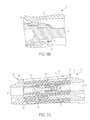
- FIGS. 6A and 6B are enlarged partial cross-sectional views of the connector illustrated in FIG. 1 , showing a retention clip of the connector;
- FIG. 7A is a partial cross-sectional view of the connector illustrated in FIG. 1 , showing a pressure relief path of the connector;
- FIG. 7B is a partial enlarged perspective view of the connector illustrated in FIG. 1 , showing an outlet of the connector;
- FIG. 7C is a partial end view of a socket port of the connector illustrated in FIG. 1 , showing the pressure relief path;
- FIG. 8 is a perspective view of a submersible electrical connector according to a second exemplary embodiment of the present invention, showing a plurality of the connectors vertically stacked on a DIN rail;
- FIG. 9 is a cross-sectional perspective view of the stacked connectors illustrated in FIG. 8 ;
- FIG. 10 is a bottom perspective view of the stacked connectors illustrated in FIG. 8 with the DIN rail removed;
- FIG. 11 is another cross-sectional perspective view of the stacked connectors illustrated in FIG. 8 ;
- FIG. 12 is an exploded perspective view of the stacked connectors illustrated in FIG. 8 .
- the present invention provides a fluid submersible electrical connector 10 , 100 that is easily mounted to a DIN rail 1 , has disconnectable (pluggable) electrical mating components, and is design to facilitate stacking of multiple connectors on the DIN rail 1 .
- the present invention provides the benefits of DIN rail mounting, preferably by a rail engagement, such as a snap-on engagement; pin and socket electrical connections; utilization of traditional or multi-element contact technology; the ability to handle power, signal, fiber, coax or a combination thereof; a pressure relief design that limits trapped air in pressure compensating (oil submerged) applications; multi-pole configurations; creepage and clearance suitable for installation within hazardous area equipment; multiple connector coupling options; accepting of a wide range of wire gage within same housing, via contact selection; housing polarization; stackability using flush sided housing to facilitate side-by-side stacking on DIN rail to minimize area, and maximize stack rigidity; single piece connector housings; and retention clips built into the contact cavities.
- a rail engagement such as a snap-on engagement
- pin and socket electrical connections utilization of traditional or multi-element contact technology
- the ability to handle power, signal, fiber, coax or a combination thereof a pressure relief design that limits trapped air in pressure compensating (oil submerged) applications
- multi-pole configurations
- the connectors of the present invention are preferably stackable, as seen in FIGS. 5 and 10 . Multiple connectors may be used alongside each other along the DIN rail 1 .
- the connectors' housings therefore, preferably have flush sides to facilitate side-by-side stacking This minimizes the area used in the enclosure and maximizes the stack rigidity. Stacking the connectors side-by-side in accordance with the present invention does not hinder the ability to attach and remove the mating connector components from the DIN rail.
- FIGS. 1-5 illustrate a first exemplary embodiment of the connector 10 of the present invention.
- the connector 10 generally includes first and second mating components 12 and 14 , and a rail engagement 16 for mounting the connector 10 to the DIN rail 1 .
- the first and second mating components 12 and 14 may be a plug and receptacle, respectively, wherein the first mating component 12 as one or more pin contacts 18 configured to engage one or more socket contacts 20 of the second mating component 14 .
- the connections may be machined electrical contacts.
- the present invention can also utilize contacts using different designs/manufacturing processes such as: stamped and formed, forged, extruded, and the like. In a preferred embodiment, RADSOK® technology is used as the socket contact 20 .
- RADSOK® manufactured by Amphenol Corporation, is based upon a stamped and formed flat grid, uniquely twisted into a hyperbolic geometry to provide robust, high density contact to the mating pin contact.
- the RADSOK® utilizes the tensile strength properties of the flat, high conductivity alloy grid. This provides the high normal forces required for conductivity while also providing a large conductive surface area. Correspondingly low voltage drop and low temperature rise are also achieved while maintaining low insertion forces.
- the first mating component 12 has a housing 22 and one or more ports 24 for supporting the one or more pin contacts 18 .
- Each port 24 has an interface end 26 , an opposite cable termination end 28 , and a block portion 30 , therebetween. Inside each port 24 is a cavity 32 that holds an individual pin contact 18 .
- the component 12 includes three ports 24 with one of the ports 24 having a different shaped interface end that has a different shape, such as a non-cylindrical shape, than the interface ends 26 of the other ports 24 . That different shaped interface end defines a first key 34 of the first mating component 12 , as best seen in FIG. 2 , for aligning the first mating component 12 with the second mating component 14 when engaging the same.
- the second mating component 14 has a housing 36 and one or more ports 38 corresponding to the ports 24 of the first mating component 12 .
- the ports 38 support the one or more socket contacts 20 , as best seen in FIG. 3 .
- Each port 38 has an interface end 40 that is adapted to receive the interface end 26 of a corresponding port 24 of the first mating component 12 , an opposite cable termination end 42 , and a block portion 44 , therebetween.
- Inside each port 38 is a cavity 46 that holds an individual socket contact 20 .
- the component 14 includes three ports 38 with one of the ports 38 having a different shaped interface end that has a different shape, such as a non-cylindrical shape, than the interface ends 40 of the other ports 38 . That different shaped interface end defines a second key 48 of the second mating component 12 , as best seen in FIG. 2 , for aligning the second mating component 14 with the first mating component 12 when engaging the same.
- the connector 10 of the present invention provides modular contact cavities. Rather than having a single housing dedicated to, for example, three contact positions, the housings 22 and 26 are made modular. Smaller housings could be made that are single cavity contact housings and they could be designed to fit together to make any plurality of ports and contact cavities.
- the initial housing would be a base housing that would be configured to mate with the DIN rail.
- the other connector housings would be positioned and attached to any side of the base housing forming a multi-position/cavity assembly.
- the rail engagement 16 is designed to facilitate mounting of the connector 10 onto the DIN rail 1 , preferably in a snapping manner, where the connector can also be easily released from the rail.
- the rail engagement 16 could use other types of engagement, rather than snapping, such as latching.
- the rail engagement 16 may generally include a snap end 50 , a grooved end 52 opposite the snap end 50 , and a support member 54 therebetween.
- the snap end 50 includes a flexible catch 56 that hooks onto a first side 2 of the DIN rail 1 , for snappingly engaging the DIN rail 1 .
- the grooved end 52 includes a lateral groove 58 located and sized to receive a second side 3 of the DIN rail 1 .
- the support member 54 between the two ends rests on the base 4 of the DIN rail 1 .
- the rail engagement 16 is preferably disposed on the housing 36 of the second mating component 14 ; however, the rail engagement 16 may be disposed on either component 12 and 14 .
- the rail engagement 16 may be formed integrally with the housing 36 or may be formed separately and attached to the housing 36 .
- the first and second mating components 12 and 14 may be securely fastened together using a coupling component 60 .
- Any known fastening mechanism may be used to mate the two housings or components of the connector 10 together.
- the coupling component 60 may be a screw fastener that is extended through cooperating and axially aligned bores 62 and 64 of the housings 22 and 36 of the first and second mating components 12 and 14 , as seen in FIGS. 1 and 2 .
- the threaded fastener is inserted from top of the housing 22 through bore 62 and threads into the receiving end of the bore 64 of the housing 36 .
- the bores may include a tri-lobular feature that allows for the threaded fastener 60 to remain attached to the housing even when the housing is not paired with its counterpart.
- a shoulder may be molded in the bore that permits the fastener to enter through the bore, and once through, prevents it from detaching itself from the housing.
- Another alternative method for coupling the housings 22 and 36 is with a common cotter pin instead of a threaded fastener. The straight end of the pin may be inserted through the bore 62 in the housing 22 and into the bore 64 of the housing 36 . This allows for quick attachment and release.
- a latch may be incorporated into the housing 22 of the first component 12 , on the top, bottom or any side of the housing, and a reciprocal latch may be provided on the housing 36 of the second component 14 .
- a clip may also extend from the housing 22 of the first component 12 can attach to the housing 36 of the second component to ensure securement.
- the connector 10 is designed to facilitate stacking of multiple connectors on the DIN rail 1 . More specifically, the block portions 30 and 44 of the first and second mating components 12 and 14 allow multiple connectors 10 to be horizontally stacked on the DIN rail 1 such that the connectors 10 are flush or nearly flush against one another. A frame 66 may be provided on the block portion 44 of the housing 36 of the second component 14 to facilitate this flush stacking while also accommodating the coupling component 60 . Each connector 10 is individually mounted to the DIN rail 1 , using the rail engagement 16 .
- Each of the cavities 32 of the first mating component 12 and each of the cavities 46 of the second mating component 14 may include a retention clip 70 for retaining the pin and socket contacts 18 and 20 in the cavities 32 and 46 , respectively, as seen in FIGS. 6A and 6B .
- the retention clip 70 is designed to sit within the cavities 32 and 46 and abut a shoulder 72 on the contacts and a shoulder 74 of the cavities 32 and 46 . After the contact 18 , 20 is crimp terminated onto a wire or cable conductor, the contact 18 , 20 is pushed into the respective housing cavity 32 , 46 .
- the retention clip 70 is compressed as it goes through this shoulder, and expands, once beyond it.
- the retention clip 70 now expanded back to its original state, wedges itself between the contact and the housing, locking the contact within the housing.
- the retention 70 clip may be made of injection molded plastic, and preferably has a hollow-cylindrically shaped, with a section cutout of its wall to allow for narrowing of its outer diameter.
- the ends of the retention clip 70 may be designed with an angled face 76 . These faces 76 act to expand the retention clip 70 within the shoulder 72 of the contact when a force is placed on the cable conductor, in the direction of contact extraction. This wedges the retention clip 70 into the corner of the housing shoulder 74 and beneficially distributes the loads, thereby lowering the shearing forces.
- the force vectors are angled into the body of the housing as opposed to a direction that attempts to shear the mating shoulder out of the housing.
- the connector 10 preferably includes a pressure relief feature, as illustrated in FIGS. 7A-7C .
- the pressure relief feature includes a path 80 for fluid to successfully travel through, thereby allowing pockets of air to be displaced.
- the fluid may be any dielectric medium, such as oil.
- pressure outside the enclosure significantly increases. That causes any air pockets within the connector to shrink. The reverse is true as well. When it ascends, the air pockets augment.
- the pressure relief path 80 is provided for the air to escape.
- the pressure relief path 80 is preferably defines an S-shaped pattern in the block portions 30 and 44 of the first and second components 12 and 14 .
- the pressure relief path 80 is in fluid communication with the contact cavities 32 and 46 at one end 82 ( FIG. 7A ) of the path and in fluid communication with the exterior of the connector 10 via an outlet 82 ( FIG. 7B ).
- the outlet 82 may be disposed in one or more of the top, bottom and side walls of the component housings 22 and 36 .
- the pressure relief path 80 may also extend around the cavities 32 and 46 of the components, as seen in FIG. 7C . Air may also escape through the tolerance located within each mated pole 24 and 38 and outlets on the exterior of one or more of the components 12 and 14 of the connector.
- Air can travel around the cylindrical walls of the ports 24 and 38 as it is submersed in a liquid.
- the liquid can fill the voids pushing the air pockets out of the connector.
- each shoulder that holds the contacts 18 and 20 via the retention clip 70 may have one or more paths 84 that also allow liquid to flow in and remove air.
- Creepage distance is the shortest path across the insulation surface between two conductive parts. Proper creepage distance protects against tracking, which is an electrical leak that could cause deterioration on the surface. Clearance distance denotes the shortest path through air between two conductive parts. Adequate clearance helps prevent dielectric breakdown between electrodes caused by the ionization of air. Both creepage and clearance are preferred to avoid any potential failure within the product. The required distances vary depending on voltage, location and material.
- the creepage and clearance are measured from contact to contact per housing. The mating end of the contact preferably either meets or exceeds the required distances as specified in IEC-60079-7, specification for hazardous area equipment. The same is true for the crimp end. For the receptacle housing, creepage and clearance also proves acceptable from the contacts to the DIN rail.
- FIGS. 8-12 illustrate a second exemplary embodiment of a submersible electrical connector 100 of the present invention.
- the connector 100 of the second embodiment is substantially similar to the connector 10 of the first embodiment, except that the rail engagement 116 of connector 100 includes a base plate 200 for supporting one or more of the connectors.
- This base plate 200 also allows multiple connectors 100 to be stacked in a vertical manner, one on top of the other, on the DIN rail 1 .
- the coupling component 160 of the second embodiment fastens the first and second mating components 112 and 114 to the base plate 200 .
- the first mating component 112 of the second embodiment has a housing 122 and one or more ports 124 for supporting one or more contacts.
- Each port 124 has an interface end 126 , an opposite cable termination end 128 , and a block portion 130 , therebetween.
- the block portion 130 may include detents 204 on one side and indents 206 on an opposite side of the housing 122 , which facilitate vertical stacking and alignment of like mating components 112 , as seen in FIGS. 11 and 12 . That is, the detents of one first mating component 112 may be received in the indents of another first mating component 112 when vertically stacked together. Such detents 204 substantially prevent the stacked mating components from moving with respect to one another.
- the component 112 includes at least one of port 124 that has a different shaped interface end that has a different shape, such as a non-cylindrical shape, than the interface ends 126 of the other ports 124 , thereby defining a first key 134 .
- the second mating component 114 has a housing 136 and one or more ports 138 corresponding to the ports 124 of the first mating component 112 .
- the ports 138 support the one or more contacts.
- Each port 138 has an interface end 140 that is adapted to receive the interface end 126 of a corresponding port 124 of the first mating component 112 , an opposite cable termination end 142 , and a block portion 144 , therebetween.
- the block portion 144 includes detents 208 and opposite indents 210 to facilitate vertical stacking of multiple components 114 .
- at least one port 138 of the second mating component 114 defines a second key 148 for aligning the second mating component 114 with the first mating component 112 when engaging the same.
- the rail engagement 116 of the second embodiment is similar to the rail engagement 16 of the first embodiment, except for the base plate 200 .
- the base plate 200 is configured to span along a portion of the length of the DIN rail 1 .
- a single or multiple connectors 100 may be fastened to the base plate 200 by extending a coupling component 160 , such as a treaded fastener, through designated bores 162 and 164 in the housings of the first and second mating components, as seen in FIGS. 9 and 12 .
- Anchors 202 may be provided on the base plate 200 for receiving the ends of the threaded fasteners 160 .
- the rail engagement 116 of the second embodiment may generally include a snap end 150 , a grooved end 152 opposite the snap end 150 , and a support member 154 therebetween.
- the snap end 150 , grooved end 152 and support member 154 extend from the base plate 200 away from the stacked connectors, as seen in FIG. 10 .
- the rail engagement 116 including the base plate 200 may be formed as a unitary one-piece member, or the snap end 150 , grooved end 152 and support member 154 may be separately attached to the base plate 200 .
- the snap end 150 includes a flexible catch 156 that hooks onto a first side 2 of the DIN rail 1 , for snappingly engaging the DIN rail 1 .
- the grooved end 152 includes a lateral groove 158 located and sized to receive a second side 3 of the DIN rail 1 .
- the support member 154 between the two ends rests on the base 4 of the DIN rail 1 .
- first and second mating components may be either plug or receptacle components supporting either pin or socket contacts.
- the connector of the present invention may accept a range of conductor sizes.
- the mating end of the contacts may remain the same, however the contact wire wells may be sized to accommodate different wire sizes. In this commonality, the housings accept all contacts, regardless of wire size.
Landscapes
- Engineering & Computer Science (AREA)
- Manufacturing & Machinery (AREA)
- Connector Housings Or Holding Contact Members (AREA)
Priority Applications (7)
| Application Number | Priority Date | Filing Date | Title |
|---|---|---|---|
| US14/741,969 US9490597B2 (en) | 2014-09-04 | 2015-06-17 | Rail mounted electrical connector |
| CA2902611A CA2902611C (fr) | 2014-09-04 | 2015-09-01 | Raccord electrique submersible dote d'un dispositif de fixation a rail |
| EP15183708.5A EP2993738A1 (fr) | 2014-09-04 | 2015-09-03 | Connecteur électrique submersible à rail de fixation |
| JP2015173693A JP2016058386A (ja) | 2014-09-04 | 2015-09-03 | レールマウントを備えた液没可能な電気コネクタ |
| AU2015221555A AU2015221555A1 (en) | 2014-09-04 | 2015-09-04 | Submersible electrical connector with rail mounting |
| CN201510561379.8A CN105406301A (zh) | 2014-09-04 | 2015-09-06 | 具有轨道安装的可浸电连接器 |
| HK16110939.5A HK1222951A1 (zh) | 2014-09-04 | 2016-09-15 | 具有轨道安装的可浸电连接器 |
Applications Claiming Priority (2)
| Application Number | Priority Date | Filing Date | Title |
|---|---|---|---|
| US201462045930P | 2014-09-04 | 2014-09-04 | |
| US14/741,969 US9490597B2 (en) | 2014-09-04 | 2015-06-17 | Rail mounted electrical connector |
Publications (2)
| Publication Number | Publication Date |
|---|---|
| US20160072243A1 US20160072243A1 (en) | 2016-03-10 |
| US9490597B2 true US9490597B2 (en) | 2016-11-08 |
Family
ID=54062678
Family Applications (1)
| Application Number | Title | Priority Date | Filing Date |
|---|---|---|---|
| US14/741,969 Active US9490597B2 (en) | 2014-09-04 | 2015-06-17 | Rail mounted electrical connector |
Country Status (7)
| Country | Link |
|---|---|
| US (1) | US9490597B2 (fr) |
| EP (1) | EP2993738A1 (fr) |
| JP (1) | JP2016058386A (fr) |
| CN (1) | CN105406301A (fr) |
| AU (1) | AU2015221555A1 (fr) |
| CA (1) | CA2902611C (fr) |
| HK (1) | HK1222951A1 (fr) |
Cited By (2)
| Publication number | Priority date | Publication date | Assignee | Title |
|---|---|---|---|---|
| CN113270752A (zh) * | 2021-04-19 | 2021-08-17 | 深圳市创杰峰控制科技有限公司 | 一种高效的i/o信号转接模块 |
| US11223163B2 (en) * | 2019-06-26 | 2022-01-11 | Radiall | Power connection module, with a system for locking/unlocking electric cable terminations in the module, terminal block comprising a plurality of independent connection modules |
Families Citing this family (9)
| Publication number | Priority date | Publication date | Assignee | Title |
|---|---|---|---|---|
| US8992238B2 (en) * | 2010-07-12 | 2015-03-31 | Ferno-Washington, Inc. | Mounting system having a mounting plate with mounting studs and electrical contacts |
| CN106129681A (zh) * | 2016-08-08 | 2016-11-16 | 杭州新湾科技股份有限公司 | 控制器模块的can总线连接器 |
| CN107785729A (zh) * | 2016-08-27 | 2018-03-09 | 山西传控电子科技有限公司 | 一种用于蓄电池插头短路保护的保护器 |
| JP6486309B2 (ja) * | 2016-10-06 | 2019-03-20 | 矢崎総業株式会社 | コネクタ |
| US10116108B1 (en) * | 2016-11-01 | 2018-10-30 | Green Creative Ltd. | Track-lighting adapter with universal housing |
| CN107275844B (zh) * | 2017-07-21 | 2024-02-23 | 河南天海电器有限公司 | 一种充电插座端子的固定结构及装配方法 |
| CN109787019A (zh) * | 2017-11-10 | 2019-05-21 | 许继电气股份有限公司 | 接线端子模块、接线端子及接线端子安装座 |
| CN110429408A (zh) * | 2019-07-22 | 2019-11-08 | 深圳市精实机电科技有限公司 | 一种用于锂电池化成分容设备换型的大电流快速接插装置 |
| EP3961831B1 (fr) * | 2020-08-27 | 2024-09-11 | TE Connectivity Germany GmbH | Mécanisme de retenue pour la fixation d'une unité d'équipement technique sur un rail de montage et unité d'équipement technique doté d'un tel mécanisme de retenue |
Citations (10)
| Publication number | Priority date | Publication date | Assignee | Title |
|---|---|---|---|---|
| GB1539338A (en) | 1976-12-16 | 1979-01-31 | Weidmueller Kg C | Plate for use with rail-mounted electrical terminal units |
| GB2287367A (en) | 1991-11-15 | 1995-09-13 | Egerton A C Ltd | Transmission line connectors and assemblies thereof |
| WO1996022554A2 (fr) | 1995-01-20 | 1996-07-25 | Ocean Design, Inc. | Connecteur pouvant etre accouple sous l'eau pour des applications sous haute pression |
| US6431909B1 (en) * | 2000-09-28 | 2002-08-13 | Rockwell Automation Technologies, Inc. | DIN rail attachment method and apparatus |
| US6767223B2 (en) * | 2000-04-14 | 2004-07-27 | Rockwell Automation Technologies, Inc. | Input/output device having removable module |
| US20080108248A1 (en) | 2006-11-03 | 2008-05-08 | Delta Electronics (Thailand) Public Co., Ltd. | Mechanism of fastening detachable electronic device to din rail |
| US20100297891A1 (en) | 2009-05-22 | 2010-11-25 | Weidmueller Interface Gmbh & Co. Kg | Connector for high electrical power applications |
| US20120117793A1 (en) | 2009-07-03 | 2012-05-17 | Centre National De La Recherche Scientifique | Connection device for a submersible connector |
| US8545277B2 (en) * | 2010-07-26 | 2013-10-01 | Omega Engineering, Inc. | Terminal block |
| US8961201B2 (en) * | 2010-05-10 | 2015-02-24 | Weidmueller Interface Gmbh & Co. Kg | Mounting rail bus system |
Family Cites Families (2)
| Publication number | Priority date | Publication date | Assignee | Title |
|---|---|---|---|---|
| US7309257B1 (en) * | 2006-06-30 | 2007-12-18 | Fci Americas Technology, Inc. | Hinged leadframe assembly for an electrical connector |
| US8388374B2 (en) * | 2011-04-12 | 2013-03-05 | Amphenol Corporation | Coupling system for electrical connector assembly |
-
2015
- 2015-06-17 US US14/741,969 patent/US9490597B2/en active Active
- 2015-09-01 CA CA2902611A patent/CA2902611C/fr active Active
- 2015-09-03 JP JP2015173693A patent/JP2016058386A/ja active Pending
- 2015-09-03 EP EP15183708.5A patent/EP2993738A1/fr not_active Withdrawn
- 2015-09-04 AU AU2015221555A patent/AU2015221555A1/en not_active Abandoned
- 2015-09-06 CN CN201510561379.8A patent/CN105406301A/zh active Pending
-
2016
- 2016-09-15 HK HK16110939.5A patent/HK1222951A1/zh unknown
Patent Citations (10)
| Publication number | Priority date | Publication date | Assignee | Title |
|---|---|---|---|---|
| GB1539338A (en) | 1976-12-16 | 1979-01-31 | Weidmueller Kg C | Plate for use with rail-mounted electrical terminal units |
| GB2287367A (en) | 1991-11-15 | 1995-09-13 | Egerton A C Ltd | Transmission line connectors and assemblies thereof |
| WO1996022554A2 (fr) | 1995-01-20 | 1996-07-25 | Ocean Design, Inc. | Connecteur pouvant etre accouple sous l'eau pour des applications sous haute pression |
| US6767223B2 (en) * | 2000-04-14 | 2004-07-27 | Rockwell Automation Technologies, Inc. | Input/output device having removable module |
| US6431909B1 (en) * | 2000-09-28 | 2002-08-13 | Rockwell Automation Technologies, Inc. | DIN rail attachment method and apparatus |
| US20080108248A1 (en) | 2006-11-03 | 2008-05-08 | Delta Electronics (Thailand) Public Co., Ltd. | Mechanism of fastening detachable electronic device to din rail |
| US20100297891A1 (en) | 2009-05-22 | 2010-11-25 | Weidmueller Interface Gmbh & Co. Kg | Connector for high electrical power applications |
| US20120117793A1 (en) | 2009-07-03 | 2012-05-17 | Centre National De La Recherche Scientifique | Connection device for a submersible connector |
| US8961201B2 (en) * | 2010-05-10 | 2015-02-24 | Weidmueller Interface Gmbh & Co. Kg | Mounting rail bus system |
| US8545277B2 (en) * | 2010-07-26 | 2013-10-01 | Omega Engineering, Inc. | Terminal block |
Cited By (3)
| Publication number | Priority date | Publication date | Assignee | Title |
|---|---|---|---|---|
| US11223163B2 (en) * | 2019-06-26 | 2022-01-11 | Radiall | Power connection module, with a system for locking/unlocking electric cable terminations in the module, terminal block comprising a plurality of independent connection modules |
| CN113270752A (zh) * | 2021-04-19 | 2021-08-17 | 深圳市创杰峰控制科技有限公司 | 一种高效的i/o信号转接模块 |
| CN113270752B (zh) * | 2021-04-19 | 2022-09-13 | 深圳市创杰峰控制科技有限公司 | 一种i/o信号转接模块 |
Also Published As
| Publication number | Publication date |
|---|---|
| CA2902611A1 (fr) | 2016-03-04 |
| CA2902611C (fr) | 2022-07-19 |
| CN105406301A (zh) | 2016-03-16 |
| EP2993738A1 (fr) | 2016-03-09 |
| AU2015221555A1 (en) | 2016-03-24 |
| US20160072243A1 (en) | 2016-03-10 |
| JP2016058386A (ja) | 2016-04-21 |
| HK1222951A1 (zh) | 2017-07-14 |
Similar Documents
| Publication | Publication Date | Title |
|---|---|---|
| US9490597B2 (en) | Rail mounted electrical connector | |
| US8262405B1 (en) | Wire-to-wire connector | |
| EP2225804B1 (fr) | Connecteur électrique comprenant un tapis d'étanchéité | |
| US8087948B2 (en) | Waterproof structure for connector housing | |
| US9337570B2 (en) | Female connector | |
| US20100193008A1 (en) | Electrical Connection System For Photovoltaic Solar Installations | |
| CN117595020A (zh) | 电插接连接部的插接连接器以及由其形成的电插接连接部 | |
| US20170110824A1 (en) | Plug | |
| CN104254949A (zh) | 插塞连接器 | |
| JP2009164105A (ja) | 第1コネクタ、第2コネクタ及び電気接続装置 | |
| US8905797B2 (en) | Electrical connector | |
| NZ202407A (en) | Multicontact insulation displacement connector | |
| EP3113293A1 (fr) | Élément de joint en coin périphérique | |
| EP3460923B1 (fr) | Connecteur électrique à montage en panneau avec face d'accouplement résistant à l'humidité | |
| US20170093075A1 (en) | Connector | |
| KR20190076885A (ko) | 억제 리브를 갖는 리셉터클 커넥터 하우징 | |
| CN104882706A (zh) | 电连接器及电连接器组件 | |
| US11901688B2 (en) | Adapter housing for a contact insert for fixing on a top-hat rail | |
| US20100081332A1 (en) | Connector | |
| KR102782781B1 (ko) | 나사 접촉부 및 크림프 접촉부를 위한 절연체 | |
| KR20250117826A (ko) | 전기 플러그 커넥터용 플러그 커넥터 인서트 | |
| CN116706588A (zh) | 一种接线端子 | |
| BR102015021516A2 (pt) | Submersible electric connector with rail mounting | |
| US12401163B2 (en) | Single pair connector module | |
| US20250164704A1 (en) | Connector system for optical fibres and assembly device |
Legal Events
| Date | Code | Title | Description |
|---|---|---|---|
| AS | Assignment |
Owner name: AMPHENOL CORPORATION, CONNECTICUT Free format text: ASSIGNMENT OF ASSIGNORS INTEREST;ASSIGNORS:ARCYKIEWICZ, ROBERT;GIFFORD, WILLIAM J;REEL/FRAME:039958/0886 Effective date: 20161004 |
|
| STCF | Information on status: patent grant |
Free format text: PATENTED CASE |
|
| MAFP | Maintenance fee payment |
Free format text: PAYMENT OF MAINTENANCE FEE, 4TH YEAR, LARGE ENTITY (ORIGINAL EVENT CODE: M1551); ENTITY STATUS OF PATENT OWNER: LARGE ENTITY Year of fee payment: 4 |
|
| MAFP | Maintenance fee payment |
Free format text: PAYMENT OF MAINTENANCE FEE, 8TH YEAR, LARGE ENTITY (ORIGINAL EVENT CODE: M1552); ENTITY STATUS OF PATENT OWNER: LARGE ENTITY Year of fee payment: 8 |