US9493233B2 - Cavity acoustic tones suppression - Google Patents
Cavity acoustic tones suppression Download PDFInfo
- Publication number
- US9493233B2 US9493233B2 US14/776,115 US201414776115A US9493233B2 US 9493233 B2 US9493233 B2 US 9493233B2 US 201414776115 A US201414776115 A US 201414776115A US 9493233 B2 US9493233 B2 US 9493233B2
- Authority
- US
- United States
- Prior art keywords
- rods
- cavity
- leading edge
- rod
- flow
- Prior art date
- Legal status (The legal status is an assumption and is not a legal conclusion. Google has not performed a legal analysis and makes no representation as to the accuracy of the status listed.)
- Expired - Fee Related
Links
Images


Classifications
-
- F—MECHANICAL ENGINEERING; LIGHTING; HEATING; WEAPONS; BLASTING
- F15—FLUID-PRESSURE ACTUATORS; HYDRAULICS OR PNEUMATICS IN GENERAL
- F15D—FLUID DYNAMICS, i.e. METHODS OR MEANS FOR INFLUENCING THE FLOW OF GASES OR LIQUIDS
- F15D1/00—Influencing flow of fluids
- F15D1/002—Influencing flow of fluids by influencing the boundary layer
-
- B—PERFORMING OPERATIONS; TRANSPORTING
- B64—AIRCRAFT; AVIATION; COSMONAUTICS
- B64C—AEROPLANES; HELICOPTERS
- B64C23/00—Influencing air flow over aircraft surfaces, not otherwise provided for
- B64C23/005—Influencing air flow over aircraft surfaces, not otherwise provided for by other means not covered by groups B64C23/02 - B64C23/08, e.g. by electric charges, magnetic panels, piezoelectric elements, static charges or ultrasounds
-
- B—PERFORMING OPERATIONS; TRANSPORTING
- B64—AIRCRAFT; AVIATION; COSMONAUTICS
- B64C—AEROPLANES; HELICOPTERS
- B64C23/00—Influencing air flow over aircraft surfaces, not otherwise provided for
- B64C23/06—Influencing air flow over aircraft surfaces, not otherwise provided for by generating vortices
-
- F—MECHANICAL ENGINEERING; LIGHTING; HEATING; WEAPONS; BLASTING
- F15—FLUID-PRESSURE ACTUATORS; HYDRAULICS OR PNEUMATICS IN GENERAL
- F15D—FLUID DYNAMICS, i.e. METHODS OR MEANS FOR INFLUENCING THE FLOW OF GASES OR LIQUIDS
- F15D1/00—Influencing flow of fluids
- F15D1/002—Influencing flow of fluids by influencing the boundary layer
- F15D1/0025—Influencing flow of fluids by influencing the boundary layer using passive means, i.e. without external energy supply
-
- F—MECHANICAL ENGINEERING; LIGHTING; HEATING; WEAPONS; BLASTING
- F15—FLUID-PRESSURE ACTUATORS; HYDRAULICS OR PNEUMATICS IN GENERAL
- F15D—FLUID DYNAMICS, i.e. METHODS OR MEANS FOR INFLUENCING THE FLOW OF GASES OR LIQUIDS
- F15D1/00—Influencing flow of fluids
- F15D1/10—Influencing flow of fluids around bodies of solid material
- F15D1/12—Influencing flow of fluids around bodies of solid material by influencing the boundary layer
-
- B—PERFORMING OPERATIONS; TRANSPORTING
- B64—AIRCRAFT; AVIATION; COSMONAUTICS
- B64C—AEROPLANES; HELICOPTERS
- B64C2230/00—Boundary layer controls
- B64C2230/08—Boundary layer controls by influencing fluid flow by means of surface cavities, i.e. net fluid flow is null
-
- Y—GENERAL TAGGING OF NEW TECHNOLOGICAL DEVELOPMENTS; GENERAL TAGGING OF CROSS-SECTIONAL TECHNOLOGIES SPANNING OVER SEVERAL SECTIONS OF THE IPC; TECHNICAL SUBJECTS COVERED BY FORMER USPC CROSS-REFERENCE ART COLLECTIONS [XRACs] AND DIGESTS
- Y02—TECHNOLOGIES OR APPLICATIONS FOR MITIGATION OR ADAPTATION AGAINST CLIMATE CHANGE
- Y02T—CLIMATE CHANGE MITIGATION TECHNOLOGIES RELATED TO TRANSPORTATION
- Y02T50/00—Aeronautics or air transport
- Y02T50/10—Drag reduction
-
- Y02T50/166—
Definitions
- the present invention relates to methods and systems for suppression of acoustic tones and/or resonance and/or other acoustic tone effects in cavities for when they are moving relative to an ambient fluid.
- the present invention relates in particular to, but is not limited to, such methods and systems for cavities recessed in a surface, for example in a surface of a vehicle, for example aircraft cavities, for example bays, when the aircraft is travelling through air.
- a shear layer is formed between (i) the moving ambient air that is flowing across the surface and across the top of the recessed cavity, and (ii) the static air in the cavity (from the reference point of the aircraft).
- a vortex is shed from the cavity leading edge and grows as it travels down the shear layer and impacts on the aft (trailing) wall of the bay resulting in the emission of noise. Also the acoustic wave travels back upstream inside the bay.
- the fluctuating pressure of the acoustic wave may either result in vortices being shed from the leading edge cavity lip or an increase in the growth rate of the vortices such that a series of vortices is formed down the shear layer at a preferential rate which is related to the frequency of the upstream acoustic wave.
- the vortices grow into large scale structures as they propagate downstream in the shear layer and then impact the aft (trailing) wall of the bay at a characteristic rate. This results in acoustic noise being generated at a characteristic rate which may be described as acoustic tones of a characteristic frequency.
- the frequency of the tones may be formulated using Rossiter's equation. It can be seen that there is a feedback loop formed by the passage of the vortices and the upstream propagating acoustic wave.
- U.S. Pat. No. 5,699,981 discloses an aircraft cavity acoustic resonance suppression system which comprises a small diameter, substantially cylindrically shaped member disposed substantially parallel to and spaced up to a distance corresponding to about three airflow boundary layer thicknesses from the surface of an aircraft near the leading edge of the cavity and transverse to airflow thereacross.
- An actuator is provided to select the adjustment of the spacing between the member and the aircraft surface according to different operational speeds and hence different operational boundary layer thicknesses as the member's spacing of about three airflow boundary layer thicknesses from the surface of the aircraft is disclosed as critical.
- the present inventor has realised that it would be desirable to provide a form of suppression by generating multiple fine scale turbulances i.e. resulting in multiple small vortices, within the shear layer, thereby disrupting the formation of large scale vortices in the shear layer which are part of the tone generation process, and moreover to provide that the multiple fine scale turbulances tend not to combine into larger ones.
- the present inventor has further realised that one way, for example, to deter the combination of the fine scale turbulence into larger ones would be to increase the thickness of the shear layer formed at the cavity (note for example, that in contrast the prior art arrangement disclosed in U.S. Pat. No. 5,699,981 does not have a tendency to thicken the shear layer).
- the present inventor has realised that, conventionally, an upstream acoustic wave interacts with the vortices in the shear layer at approximately common times i.e. they display a temporal coherence.
- the present inventor has realised that in contrast, by providing a thicker shear layer, the vortices closer to the stream flow will propagate downstream faster than those closer to the static air in the bay. The present inventor has realised that therefore at some point downstream the vortices will arrive at different times to each other.
- this loss of temporal coherence will disrupt the formation of the conventional large scale turbulent structures that would otherwise play a key role in the generation of unwanted acoustic tones.
- the present inventor has further realised that it would be desirable to provide a suppression system comprising elements that readily accommodated differing boundary layer thicknesses without requiring positional adjustment, unlike the system disclosed in U.S. Pat. No. 5,699,981.
- the present invention provides a cavity system, comprising: a cavity and a plurality of rods; the rods are positioned in the proximity of a leading edge of the cavity, the leading edge being relative to an actual or intended flow direction of a fluid over the cavity; the rods extending across at least a part of a width of the cavity in a perpendicular or oblique angle to the actual or intended flow direction.
- the cavity may be a cavity recessed in a surface.
- the surface may be a surface comprised by a vehicle.
- the vehicle may be an aircraft, or a missile, or any other type of vehicle, for example a car or a lorry, or a sea vessel, including for example a submarine.
- the cavity system may be arranged with all the rods downstream of the leading edge.
- One or more of the rods may be positioned further along the flow direction compared to one or more of the other rods.
- the positioning of one or more of the rods further along the flow direction compared to one or more of the other rods may provide a zig-zag pattern of rod positions.
- One or more flow alteration elements may be provided on one or more of the rods.
- At least some of the flow alteration elements may comprise or provide additional edges at the one or more rods that are in addition to the edge or edges provided by the underlying shape of the rod or rods.
- At least some of the flow alteration elements may comprise a channel passing through the rod.
- At least some of the flow alteration elements may comprise a protrusion extending from the rod.
- Flow alteration elements may be at different positions along the rod on different rods.
- At least two different types of flow alteration elements may be provided.
- the rods may be positioned at a distance from the leading edge that is ⁇ 0.2 ⁇ the distance between the leading edge and an aft edge.
- the rods may be positioned at a distance from the leading edge that is ⁇ 0.1 ⁇ the distance between the leading edge and the aft edge.
- the rods may be positioned at a distance from the leading edge that is ⁇ 0.05 ⁇ the distance between the leading edge and the aft edge.
- the number (n) of rods in the plurality may be 2 ⁇ n ⁇ 6.
- the number (n) of rods in the plurality may be 3 ⁇ n ⁇ 6.
- the effect of the rods may be to increase the thickness of the shear layer.
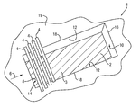
- FIG. 1 is a schematic illustration (not to scale) of a perspective view of a cavity acoustic tones suppression system
- FIG. 2 is a schematic cross-sectional view (not to scale) of the suppression system of FIG. 1 ;
- FIG. 3 is a further schematic cross-sectional view (not to scale) of the suppression system 1 of FIGS. 1 and 2 ;
- FIG. 4 is a perspective view of a rod with flow alteration elements provided on it;
- FIG. 5 is a cross-sectional view of the rod of FIG. 4 ;
- FIG. 6 is a perspective view of a rod with flow alteration elements provided on it;
- FIG. 7 is a schematic cross-sectional view (not to scale) of a suppression system in which all the rods are offset from each other;
- FIG. 8 is a schematic cross-sectional view (not to scale) of a suppression system in which some of the rods are offset from some but not all of the other rods;
- FIG. 9 is a schematic cross-sectional view (not to scale) of a suppression system in which all of the rods are positioned upstream of the leading edge of a cavity.
- FIG. 10 is a schematic cross-sectional view (not to scale) of a suppression system in which some of the rods are positioned upstream of the leading edge of a cavity and some of the rods are positioned downstream of the leading edge of the cavity.
- FIG. 1 is a schematic illustration (not to scale) of a perspective view of a first embodiment of a cavity acoustic tones suppression system 1 (hereinafter referred to as the suppression system 1 ).
- the cavity acoustic tone suppression system comprises a cavity 2 and a plurality of rods 4 .
- the cavity 2 is in a surface 19 .
- the number of rods 4 in the plurality of rods 4 is four.
- the cavity 2 is a cavity 2 recessed in a surface 19 of an aircraft (in FIG. 2 the external boundary of the surface 19 is schematically identified by a zig-zag line to indicate in conventional drawing-style form that the extent of the surface 19 being schematically shown is not necessarily limited to the drawing page).
- the surface 19 is substantially planar, although not necessarily flat and not necessarily without non-uniformities or items fixed thereto.
- the cavity 2 is rectangular and comprises a planar base 3 . In FIG. 1 the planar base 3 is schematically shown in hatched shading.
- the cavity 2 further comprises, defined relative to an actual or intended flow direction 6 (the flow direction 6 being across, or over, the surface 19 and the cavity 2 ), a leading wall 8 , an aft (trailing) wall 10 , and two side walls 12 . In this embodiment these walls are all perpendicular to the planar base 3 .
- the cavity 2 comprises, for each of these walls respectively, a leading edge 14 , an aft (trailing) edge 16 , and two side edges 18 .
- the rods 4 extend across the width of the cavity, i.e. in a transverse (i.e. perpendicular) (or in other embodiments, in an oblique angle) direction to the flow direction 6 , i.e. in this embodiment parallel with the front and aft (trailing) edges and walls.
- the rods 4 are positioned downstream of the leading edge 14 (i.e. above the cavity 2 ), and the rods 4 are positioned closer to the leading edge 14 than they are to the aft (trailing) edge 16 . More particularly, in this embodiment the rods 4 are positioned such that the distance of the rods 4 from the leading edge 14 in the flow direction equals 0.05 ⁇ the total distance between the leading edge 14 and the aft (trailing) edge 14 .
- FIG. 2 is a schematic cross-sectional view (not to scale) of the suppression system 1 of FIG. 1 .
- Elements of the system shown in FIG. 2 that were also shown in FIG. 1 are the following: the cavity 2 , the planar base 3 , the plurality of rods 4 , the flow direction 6 , the leading wall 8 , the aft (trailing) wall 10 , the leading edge 14 , the aft (trailing) edge 16 , and the surface 19 (which may also be considered as the plane of the surface).
- a gap or major change in orientations in the surface 19 in effect provides the opening of the cavity 2 , and the cavity 2 is in the form of a recess in the surface 19 .
- the terminology “cavity recessed in a surface” as used herein includes cases where the overall effect or geometry of the cavity is that it will be recognised as a “cavity recessed in a surface”, even if strictly speaking the surface 19 and/or one or more of the walls 8 , 10 , 12 and/or the planar base 3 are not made from a single continuous piece or type of material.
- FIG. 2 Also shown (in dotted line form) in FIG. 2 for ease of explanation later below is a hypothetical extension 20 of the surface 19 over the cavity 2 .
- FIG. 2 Also shown in FIG. 2 is a schematic (not to scale) indication of the spacing or distance x (in the direction along the cavity i.e. in the flow direction) of the rods 4 from the leading edge 14 .
- each rod 4 is positioned directly above each other, i.e. each rod 4 is positioned at substantially the same distance x (in the direction along the cavity i.e. in the flow direction) from the leading edge 14 .
- the rods 4 may be held in position by any suitable fixture or fixing, attached either to the surface in which the cavity is formed, or any other appropriate part of the vehicle containing the cavity.
- the fixture is sized and located such as to avoid or at least minimise any impact on the operational effect of the rods regarding the cavity 2 .
- the rods may be mounted on or through a vertical bar or plate at or close to the ends of the rods.
- rods 4 are all of circular cross-sectional shape.
- rods are all of the same (circular) cross-sectional shape as each other, and are all of the same diameter as each other.
- the rods each have a uniform cross-sectional shape along their entire length.
- rods 4 all extend completely across the width of the cavity 2 .
- rods 4 are all the same length as each other and extend across the same extent of the width of the cavity as each other.
- FIG. 3 is a further schematic cross-sectional view (not to scale) of the suppression system 1 of FIGS. 1 and 2 (and indeed shows the same view as FIG. 2 , but for clarity omits certain features and reference numerals from FIG. 2 ). Elements of the system shown in FIG. 3 that were also shown in FIG. 1 and/or FIG.
- the cavity 2 are the following: the cavity 2 , the planar base 3 , the plurality of rods 4 , the flow direction 6 , the leading wall 8 , the aft (trailing) wall 10 , the leading edge 14 , the aft (trailing) edge 16 , the surface 19 that surrounds the cavity 2 , and the hypothetical extension 20 of the surface 19 over the cavity 2 .
- one effect of the plurality of rods 4 is to tend to increase the thickness of the shear layer 22 compared to if the rods 4 were not present. This is at least in part due to the rods presenting a blockage to the air flow to deflect the flow both in and out of the cavity, due at least in part to the presence of more than one rod 4 .
- the shear layer 22 is represented schematically in FIG. 2 as the region between a line representing the top 24 (i.e. furthest away from the cavity 2 ) of the shear layer 22 and a line representing the bottom 26 (i.e. closest to the cavity 2 ) of the shear layer.
- the thickness 28 of the shear layer 22 at any point along the cavity 2 is correspondingly the distance between the top 24 of the shear layer 22 and the bottom 26 of the shear layer 22 .
- a further effect of the plurality of rods 4 in particular the presence of more than one rod at different heights, is to tend to provide multiple sources of fine scale turbulence giving rise to a plurality of small vortices 30 at differing heights.
- Due at least in part to the thicker shear layer 22 in particular the plurality of heights at which the vortices are shed due to the different heights of the different rods 4 , the vortices 30 tend not to combine into larger ones.
- the vortices 30 closer to the top 24 of the shear layer 22 (i.e.
- flow alteration elements are provided on one or more (preferably all) of the rods 4 .
- the flow alteration elements may increase the deflection of the vortices 30 into and/or out of the cavity 2 , thereby further enhancing the thickening of the shear layer 22 .
- the flow alteration elements may additionally or alternatively serve as additional sources of fine scale turbulence giving rise to yet further small vortices 30 , hence tending to provide yet further loss of temporal coherence.
- FIGS. 4 and 5 are a schematic illustration (not to scale) of a rod 4 of one such embodiment with flow alteration elements provided on one or more (preferably all) of the rods 4 .
- FIG. 4 is a perspective view of the rod 4
- FIG. 5 is a cross-sectional view of the rod 4 .
- the rod 4 includes a series of channels 34 (i.e. in this embodiment the flow alteration elements are the channels 34 ) passing through the rod 4 (either parallel to the flow direction 6 or at an oblique angle to the flow direction 6 ) and arranged such that in operation some of the fluid impacting the rod 4 passes through the channel 34 and some of the fluid is diverted around the rod 4 , thereby providing additional sources of fine scale turbulence (hence additional vortices 30 ) and/or increasing the deflection of the vortices 30 into and/or out of the cavity 2 , thereby further enhancing the thickening of the shear layer 22 .
- the flow alteration elements are the channels 34
- the channels are arranged with their openings spaced equally apart in a single straight line along the length of the rod.
- the channel openings are may be placed at unequal distances and/or in more than one straight line and/or with some or all of them not arranged in straight lines.
- FIG. 6 is a schematic illustration (not to scale), of a rod 4 of a further such embodiment with flow alteration elements provided on one or more (preferably all) of the rods 4 .
- the rod 4 is shown in a perspective view.
- the rod 4 includes a plurality of protrusions 38 , serving as the flow alteration elements, extending from the surface of the rod 4 .
- the protrusions 38 are fin-like protrusions 38 .
- the protrusions are positioned and arranged (for example extending above and below the uppermost and bottom extremities of the longitudinal extensions of the rod 4 to provide a taller cross-section to the ambient flow direction 6 at parts of the rod 4 ) such that in operation some of the fluid impacts the protrusions 38 , thereby providing additional sources of fine scale turbulence (hence additional vortices 30 ) and/or increasing the deflection of the vortices 30 into and/or out of the cavity 2 , thereby further enhancing the thickening of the shear layer 22 .
- the rod may comprise one or plural flow alteration elements.
- each flow alteration element is a channel through a rod
- two or more channels may be provided on a single rod (or on each of a plurality of rods), the channels being arranged above each other and/or beside each other, for example.
- the flow alteration elements are protrusions, and there are plural protrusions on a given rod, the plural protrusion may be provided all on the same side of the rod, or on both sides of the rod.
- the flow alteration elements are protrusions, and there are plural protrusions on a given rod, one or more of the protrusions may extend a different distance from the rod, i.e. be of a different height, to other protrusions.
- the flow alteration elements may be arranged perpendicular and/or parallel to sides and/or surfaces of a given rod, or may be at an oblique angle thereto.
- the flow alteration elements may be arranged perpendicular and/or parallel to the flow direction, or may be at an oblique angle thereto e.g. skewed.
- the plural flow alteration elements may all be channels, or may all be protrusions, or may be a mixture of each.
- the flow alteration elements are channels through a rod and/or protrusions on the rod.
- any other forms of flow alteration elements may be provided additionally or alternatively.
- one or more of the flow alteration elements may comprise a groove or other disturbance/irregularity in the surface or shape of the rod.
- a flow alteration element is a channel through a rod or a protrusion on a rod. Both of these types may be considered as elements that comprise or provide additional edges on or at the one or more rods that are in addition to the edge or edges provided by the underlying shape of the rod or rods. In other embodiments, in addition to or instead of the channels through a rod and/or protrusions on a rod, any other suitable type or types of flow alteration elements may be provided that comprise or provide additional edges on or at the one or more rods that are in addition to the edge or edges provided by the underlying shape of the rod or rods.
- any other suitable type or types of flow alteration elements may be provided that alter the flow so as to provide additional sources of fine scale turbulence (hence additional vortices 30 ) and/or increase the deflection of the vortices 30 into and/or out of the cavity 2 , thereby further enhancing the thickening of the shear layer 22 .
- the rods 4 are all of circular cross-sectional shape. However, this need not be the case, and in other embodiments, the rods 4 may all be the same cross-sectional shape, where that shape is other than circular e.g. a non-circular curved shape, or a non-curved shape, e.g. rectangular.
- the rods 4 all extend completely across the width of the cavity 2 . However, this need not be the case, and in other embodiments one or more of the rods 4 may extend only across a part of the width of the cavity 2 , but this will be preferably at least half the width of the cavity 2 , and yet more preferably over at least three quarters (3 ⁇ 4) of the width of the cavity 2 .
- the rods 4 are all the same length as each other and extend across the same extent of the width of the cavity as each other. However, this need not be the case, and in other embodiments one or more of the rods may be a different length to the other rods and/or may extend across a different extent of the width of the cavity as other rods.
- any non-uniformity introduced into the form of one or more of the individual rods 4 will tend to provide the possibility of increased numbers or variations of sources of fine scale turbulence, with corresponding increased numbers of small vortices and/or thicker shear layer and/or increased disruption of the temporal coherence of the small vortices, any of which effects may further improve the suppression performance of the suppression system 1 .
- the following further embodiments (i) to (v) are further examples of embodiments introducing or enhancing such non-uniformity.
- the rods are all of the same (circular) cross-sectional shape as each other, and are all of the same diameter as each other. However, this need not be the case, and in other embodiments one or more of the rods may have a different cross-sectional shape and/or may have a different diameter or other relevant dimension to the other rods.
- the rods 4 each have a uniform cross-sectional shape along their entire length. However, this need not be the case, and in other embodiments one or more of the rods 4 may have a non-uniform cross-sectional shape along its entire length.
- this need not be the case, and in other embodiments one or more of the distances between adjacent rods 4 in the above mentioned direction may be unequal to the distance between two other adjacent rods 4 e.g. y 1 ⁇ y 2 ⁇ y 3 , or y 1 ⁇ y 2 y 3 , and so on.
- each rod 4 is positioned directly above each other, i.e. each rod 4 is positioned at substantially the same distance x (in the direction along the cavity i.e. in the flow direction) from the leading edge 14 .
- one or more of the rods 4 may be positioned at different distances (in the direction along the cavity i.e. in the flow direction) from the leading edge 14 , i.e. one or more of the rods 4 may be offset from one or more of the other rods 4 in the direction along the cavity i.e. in the flow direction.
- Any offset may be such that two rods are completely offset, i.e. there is no overlap, i.e. the difference between their respective differences is equal to or greater than the width of the rods, or may alternatively be with an overlap therebetween i.e. the difference between their respective differences is less than the width of the rods.
- FIG. 7 and FIG. 8 Some examples of embodiments in which one or more of the rods 4 is offset from one or more of the other rods 4 in the direction along the cavity i.e. in the flow direction, are shown in FIG. 7 and FIG. 8 .
- FIG. 7 and FIG. 8 the suppression system 1 (not to scale) is viewed from the same side view as FIGS. 2 to 6 and the same reference numerals are used for the same features as were used in the earlier Figures.
- the rods 4 are positioned downstream of the leading edge 14 (i.e. above the cavity 2 ), and the rods 4 are positioned closer to the leading edge 14 than they are to the aft (trailing) edge 16 . More particularly, in this embodiment the rods 4 are positioned such that the distance of the rods 4 from the leading edge 14 equals 0.05 ⁇ the total distance between the leading edge 14 and the aft (trailing) edge 14 . However this need not be the case, and in other embodiments the rods 4 may be positioned at any position downstream of the leading edge that is in the proximity of the leading edge.
- This may include, for example, any position downstream of the leading edge that is closer to the leading edge 14 than it is to the aft (trailing) edge 16 , as some degree of suppression will still tend to occur. However, preferably the rods 4 are positioned closer to the leading edge than that, as then an even greater extent of the suppression effect will tend to occur. For example, as well as the preferred positioning at a distance downstream from the leading edge of 0.05 ⁇ the total distance between the leading edge 14 and the aft (trailing) edge 16 , even more preferred is any positioning at a distance of 0.05 ⁇ the total distance, but also preferred more generally is positioning at a distance of 0.1 ⁇ the total distance, and yet more generally any positioning at a distance of 0.2 ⁇ the total distance.
- the rods 4 are positioned downstream of the leading edge 14 (i.e. above the cavity 2 ). However, this need not be the case, and in other embodiments one or more of the rods may be positioned upstream of the leading edge 14 , i.e. above the surface 19 rather than above the cavity 2 . In such embodiments, the rods 4 may be positioned upstream from the leading edge 14 at any position in the proximity of the leading edge, which may be at any distance from the leading edge ⁇ half the distance between the leading edge 14 and the aft (trailing) edge 16 .
- the rods 4 are positioned upstream from the leading edge at a distance from the leading edge ⁇ 0.2 ⁇ the distance between the leading edge 14 and the aft (trailing) edge 16 ; more preferably at a distance from the leading edge ⁇ 0.1 ⁇ the distance between the leading edge 14 and the aft (trailing) edge 16 ; and yet more preferably at a distance from the leading edge ⁇ 0.05 ⁇ the distance between the leading edge 14 and the aft (trailing) edge 16 .
- one embodiment where all of the rods 4 are positioned upstream of the leading edge 14 is shown in FIG.
- FIG. 9 and one embodiment where some of the rods 4 are positioned upstream of the leading edge 14 and some of the rods are positioned downstream of the leading edge 14 (i.e. over the cavity 2 ) is shown in FIG. 10 .
- the suppression system 1 (not to scale) is viewed from the same side view as FIGS. 2 to 8 and the same reference numerals are used for the same features as were used in the earlier Figures).
- one or more of the rods may be positioned directly over the leading edge 14 , as discussed earlier above.
- the cavity 2 is rectangular and comprises a planar base 3 , the cavity 2 further comprises, defined relative to an actual or intended flow direction 6 , a leading wall 8 , an aft (trailing) wall 10 , and two side walls 12 , and these walls are all perpendicular to the planar base 3 .
- these specific cavity details are not essential, and in other embodiments any other cavity shape may be present.
- the walls need not be straight or perpendicular
- the cavity may be defined by one or more walls forming a curved or partially curved perimeter to the cavity, the perimeter may be irregularly shaped, one or more walls may be sloping, the base and or one or more walls may be undulating or sloped, and so on.
- the suppression will tend to occur more strongly the more straightforwardly the leading edge (compared to the actual or intended airflow direction) is defined or present.
- the rods may cross a rectangular cavity with a transverse direction that is at an oblique angle to the stated direction, but contains a resolved element of that direction and hence of its effect, for example at a direction of 15°, 30° or 45° to the direction parallel to the leading edge 14 .
- the number of rods 4 in the plurality of rods 4 is four. However, this need not be the case, and in other embodiments there may be any other numbers of rods in the plurality, for example two, three, five and so on, although depending on the dimensions of the cavity and the rods, typically use of only two rods will give only some of the available beneficial effects, and the useful effect of further rods will typically diminish beyond six rods, hence a first preferred range for the number (n) of rods in the plurality of rods is n ⁇ 3, another preferred range for the number (n) of rods in the plurality is 2 ⁇ n ⁇ 6, and another preferred range for the number (n) of rods in the plurality is 3 ⁇ n ⁇ 6.
- the above described surface in which the cavity is recessed may be a surface of a vehicle.
- the vehicle may be an aircraft, or a missile, or any other type of vehicle, for example a car or a lorry, or a sea vessel, including for example a submarine.
Landscapes
- Engineering & Computer Science (AREA)
- Aviation & Aerospace Engineering (AREA)
- Physics & Mathematics (AREA)
- Fluid Mechanics (AREA)
- Mechanical Engineering (AREA)
- General Engineering & Computer Science (AREA)
- Turbine Rotor Nozzle Sealing (AREA)
- Physical Or Chemical Processes And Apparatus (AREA)
- Structures Of Non-Positive Displacement Pumps (AREA)
Applications Claiming Priority (6)
| Application Number | Priority Date | Filing Date | Title |
|---|---|---|---|
| EP13275065.4A EP2778046A1 (de) | 2013-03-15 | 2013-03-15 | Unterdrückung von akustischen Hohlraumtönen |
| GB201304718A GB201304718D0 (en) | 2013-03-15 | 2013-03-15 | Cavity acoustic tones suppression |
| EP13275065.4 | 2013-03-15 | ||
| EP13275065 | 2013-03-15 | ||
| GB1304718.8 | 2013-03-15 | ||
| PCT/GB2014/050761 WO2014140590A1 (en) | 2013-03-15 | 2014-03-13 | Cavity acoustic tones suppression |
Publications (2)
| Publication Number | Publication Date |
|---|---|
| US20160031548A1 US20160031548A1 (en) | 2016-02-04 |
| US9493233B2 true US9493233B2 (en) | 2016-11-15 |
Family
ID=50342349
Family Applications (1)
| Application Number | Title | Priority Date | Filing Date |
|---|---|---|---|
| US14/776,115 Expired - Fee Related US9493233B2 (en) | 2013-03-15 | 2014-03-13 | Cavity acoustic tones suppression |
Country Status (5)
| Country | Link |
|---|---|
| US (1) | US9493233B2 (de) |
| EP (1) | EP2969748B1 (de) |
| ES (1) | ES2642407T3 (de) |
| GB (1) | GB2514452C (de) |
| WO (1) | WO2014140590A1 (de) |
Cited By (3)
| Publication number | Priority date | Publication date | Assignee | Title |
|---|---|---|---|---|
| US20160031290A1 (en) * | 2014-07-31 | 2016-02-04 | Airbus Operations (Sas) | Aircraft turbomachine comprising a deflector |
| US11027826B2 (en) * | 2017-08-25 | 2021-06-08 | Mitsubishi Heavy Industries, Ltd. | Aircraft |
| US12560102B2 (en) * | 2022-06-23 | 2026-02-24 | Rolls-Royce Deutschland Ltd & Co Kg | Air intake |
Families Citing this family (1)
| Publication number | Priority date | Publication date | Assignee | Title |
|---|---|---|---|---|
| WO2018069671A1 (en) * | 2016-10-11 | 2018-04-19 | Bae Systems Plc | Cavity acoustic tones suppression |
Citations (18)
| Publication number | Priority date | Publication date | Assignee | Title |
|---|---|---|---|---|
| US2451479A (en) | 1945-04-28 | 1948-10-19 | Walter S Diehl | Airflow stabilizer |
| GB614274A (en) | 1946-07-09 | 1948-12-13 | Albert George Elliott | Improvements in or relating to the guards for air-intakes in aircraft |
| US2663993A (en) | 1945-10-10 | 1953-12-29 | Westinghouse Electric Corp | Deicing apparatus |
| US2749064A (en) | 1952-11-19 | 1956-06-05 | Jr William H Kuhlman | Aerodynamic deflector and diffuser |
| DE3534268A1 (de) | 1985-09-26 | 1987-04-02 | Deutsche Forsch Luft Raumfahrt | Zur vermeidung von stroemungsabloesungen ausgebildete oberflaeche eines umstroemten koerpers |
| DE3609541A1 (de) | 1986-03-21 | 1987-09-24 | Deutsche Forsch Luft Raumfahrt | Verminderten stroemungswiderstand durch herabgesetzte wandschubspannung aufweisende oberflaeche eines turbolent ueberstroemten koerpers |
| US5340054A (en) | 1991-02-20 | 1994-08-23 | The United States Of America As Represented By The Secretary Of The Navy | Suppressor of oscillations in airframe cavities |
| EP0673819A1 (de) | 1994-03-24 | 1995-09-27 | Gec Alsthom Transport Sa | Vorrichtung zum Reduzieren des Strömungswiderstandes einer Kavität und Fahrzeug, insbesondere Schienenfahrzeug, mit dieser Vorrichtung |
| US5699981A (en) | 1996-03-18 | 1997-12-23 | The United States Of America As Represented By The Secretary Of The Air Force | Aircraft cavity acoustic resonance suppression system |
| US6296202B1 (en) | 2000-02-09 | 2001-10-02 | The United States Of America As Represented By The Secretary Of The Air Force | Aircraft weapons bay acoustic suppression apparatus |
| US20020079405A1 (en) | 2000-07-24 | 2002-06-27 | Thombi Layukallo | Control of flow separation and related phenomena on aerodynamic surfaces |
| JP2002205639A (ja) | 2001-01-10 | 2002-07-23 | West Japan Railway Co | 棒付き凹部の空力音低減化構造 |
| US20020190164A1 (en) * | 2001-06-12 | 2002-12-19 | Eric Loth | Method and apparatus for control of shock/boundary-layer interactions |
| US6739554B1 (en) | 2003-06-02 | 2004-05-25 | The United States Of America As Represented By The Secretary Of The Air Force | Aircraft weapons bay acoustic resonance suppression system |
| DE102005007940A1 (de) | 2005-02-22 | 2006-08-24 | Mtu Aero Engines Gmbh | Triebwerk |
| US20080217485A1 (en) | 2005-12-28 | 2008-09-11 | National University Corporation Nagoya University | Smart Vortex Generator, and Aircraft, Vessel, and Rotary Machine Being Equipped with the Same |
| US20090045289A1 (en) | 2007-01-10 | 2009-02-19 | Continuum Dynamics, Inc. | Flow-driven oscillating acoustic attenuator |
| US20090045286A1 (en) | 2007-06-27 | 2009-02-19 | Kazak Composites, Incorporated | Grid fin control system for a fluid-borne object |
-
2014
- 2014-03-13 ES ES14711574.5T patent/ES2642407T3/es active Active
- 2014-03-13 WO PCT/GB2014/050761 patent/WO2014140590A1/en not_active Ceased
- 2014-03-13 US US14/776,115 patent/US9493233B2/en not_active Expired - Fee Related
- 2014-03-13 EP EP14711574.5A patent/EP2969748B1/de active Active
- 2014-03-13 GB GB1404467.1A patent/GB2514452C/en not_active Expired - Fee Related
Patent Citations (18)
| Publication number | Priority date | Publication date | Assignee | Title |
|---|---|---|---|---|
| US2451479A (en) | 1945-04-28 | 1948-10-19 | Walter S Diehl | Airflow stabilizer |
| US2663993A (en) | 1945-10-10 | 1953-12-29 | Westinghouse Electric Corp | Deicing apparatus |
| GB614274A (en) | 1946-07-09 | 1948-12-13 | Albert George Elliott | Improvements in or relating to the guards for air-intakes in aircraft |
| US2749064A (en) | 1952-11-19 | 1956-06-05 | Jr William H Kuhlman | Aerodynamic deflector and diffuser |
| DE3534268A1 (de) | 1985-09-26 | 1987-04-02 | Deutsche Forsch Luft Raumfahrt | Zur vermeidung von stroemungsabloesungen ausgebildete oberflaeche eines umstroemten koerpers |
| DE3609541A1 (de) | 1986-03-21 | 1987-09-24 | Deutsche Forsch Luft Raumfahrt | Verminderten stroemungswiderstand durch herabgesetzte wandschubspannung aufweisende oberflaeche eines turbolent ueberstroemten koerpers |
| US5340054A (en) | 1991-02-20 | 1994-08-23 | The United States Of America As Represented By The Secretary Of The Navy | Suppressor of oscillations in airframe cavities |
| EP0673819A1 (de) | 1994-03-24 | 1995-09-27 | Gec Alsthom Transport Sa | Vorrichtung zum Reduzieren des Strömungswiderstandes einer Kavität und Fahrzeug, insbesondere Schienenfahrzeug, mit dieser Vorrichtung |
| US5699981A (en) | 1996-03-18 | 1997-12-23 | The United States Of America As Represented By The Secretary Of The Air Force | Aircraft cavity acoustic resonance suppression system |
| US6296202B1 (en) | 2000-02-09 | 2001-10-02 | The United States Of America As Represented By The Secretary Of The Air Force | Aircraft weapons bay acoustic suppression apparatus |
| US20020079405A1 (en) | 2000-07-24 | 2002-06-27 | Thombi Layukallo | Control of flow separation and related phenomena on aerodynamic surfaces |
| JP2002205639A (ja) | 2001-01-10 | 2002-07-23 | West Japan Railway Co | 棒付き凹部の空力音低減化構造 |
| US20020190164A1 (en) * | 2001-06-12 | 2002-12-19 | Eric Loth | Method and apparatus for control of shock/boundary-layer interactions |
| US6739554B1 (en) | 2003-06-02 | 2004-05-25 | The United States Of America As Represented By The Secretary Of The Air Force | Aircraft weapons bay acoustic resonance suppression system |
| DE102005007940A1 (de) | 2005-02-22 | 2006-08-24 | Mtu Aero Engines Gmbh | Triebwerk |
| US20080217485A1 (en) | 2005-12-28 | 2008-09-11 | National University Corporation Nagoya University | Smart Vortex Generator, and Aircraft, Vessel, and Rotary Machine Being Equipped with the Same |
| US20090045289A1 (en) | 2007-01-10 | 2009-02-19 | Continuum Dynamics, Inc. | Flow-driven oscillating acoustic attenuator |
| US20090045286A1 (en) | 2007-06-27 | 2009-02-19 | Kazak Composites, Incorporated | Grid fin control system for a fluid-borne object |
Non-Patent Citations (6)
| Title |
|---|
| EP Search Report dated Jul. 16, 2013 of Patent Application No. 13275066.2 filed Mar. 15, 2013. |
| EP Search Report dated Nov. 13, 2013 of Patent Application No. 13275065.4 filed Mar. 15, 2013. |
| EP Search Report dated Oct. 11, 2013 of Patent Application No. 13275064.7 filed Mar. 15, 2013. |
| GB Search Report dated Jul. 24, 2013 of Patent Application No. 1304716.2 filed Mar. 15, 2013. |
| GB Search Report dated Jul. 24, 2013 of Patent Application No. 1304718.8 filed Mar. 15, 2013. |
| GB Search Report dated Jul. 24, 2013 of Patent Application No. 1304722.0 filed Mar. 15, 2013. |
Cited By (4)
| Publication number | Priority date | Publication date | Assignee | Title |
|---|---|---|---|---|
| US20160031290A1 (en) * | 2014-07-31 | 2016-02-04 | Airbus Operations (Sas) | Aircraft turbomachine comprising a deflector |
| US10518605B2 (en) * | 2014-07-31 | 2019-12-31 | Airbus Operations (Sas) | Aircraft turbomachine comprising a deflector |
| US11027826B2 (en) * | 2017-08-25 | 2021-06-08 | Mitsubishi Heavy Industries, Ltd. | Aircraft |
| US12560102B2 (en) * | 2022-06-23 | 2026-02-24 | Rolls-Royce Deutschland Ltd & Co Kg | Air intake |
Also Published As
| Publication number | Publication date |
|---|---|
| US20160031548A1 (en) | 2016-02-04 |
| GB2514452C (en) | 2019-12-25 |
| GB201404467D0 (en) | 2014-04-30 |
| EP2969748B1 (de) | 2017-08-30 |
| WO2014140590A1 (en) | 2014-09-18 |
| GB2514452A (en) | 2014-11-26 |
| GB2514452B (en) | 2016-06-08 |
| ES2642407T3 (es) | 2017-11-16 |
| EP2969748A1 (de) | 2016-01-20 |
Similar Documents
| Publication | Publication Date | Title |
|---|---|---|
| US9487289B2 (en) | Cavity acoustic tones suppression | |
| US9463754B2 (en) | Cavity acoustic tones suppression | |
| US9493233B2 (en) | Cavity acoustic tones suppression | |
| EP2778045A1 (de) | Unterdrückung von akustischen Hohlraumtönen | |
| EP2778046A1 (de) | Unterdrückung von akustischen Hohlraumtönen | |
| US20240317387A1 (en) | Cavity acoustic tones suppression | |
| EP2778044A1 (de) | Unterdrückung von akustischen Hohlraumtönen | |
| US11407497B2 (en) | Cavity acoustic tones suppression | |
| US20250145278A1 (en) | Cavity acoustic tones suppression | |
| Yeung et al. | Two-Dimensional Simulations of Multi-Stream Supersonic Jet Flow with Steady-Blowing Control | |
| Schmidt et al. | Experimental investigation of the flow field behind a bluff body equipped with fluidic oscillators | |
| Zhang et al. | Vortex–airfoil interaction noise control using virtual serrations and surface morphing generated by leading-edge blowing | |
| GB2555086A (en) | Cavity acoustic tones supression | |
| Das et al. | Supersonic flow over three dimensional cavities | |
| Rodarte Ricciardi et al. | Laminar-turbulent transition and intermittency effects on secondary tones from a NACA0012 airfoil | |
| Dennard | The Total-Pressure Recovery and Drag Characteristics of Several Auxiliary Inlets at Transonic Speeds | |
| Linn et al. | NUMERICAL INVESTIGATION OF HYPERSONIC WALL-BOUNDED SHEAR FLOWS–PART 1: EFFUSION COOLING | |
| Konishi et al. | Relation between trailing edge noise and boundary layer instability |
Legal Events
| Date | Code | Title | Description |
|---|---|---|---|
| AS | Assignment |
Owner name: BAE SYSTEMS PLC, GREAT BRITAIN Free format text: ASSIGNMENT OF ASSIGNORS INTEREST;ASSIGNOR:PATIENCE, DAVID EUAN;REEL/FRAME:036558/0464 Effective date: 20150910 |
|
| STCF | Information on status: patent grant |
Free format text: PATENTED CASE |
|
| FEPP | Fee payment procedure |
Free format text: PAYOR NUMBER ASSIGNED (ORIGINAL EVENT CODE: ASPN); ENTITY STATUS OF PATENT OWNER: LARGE ENTITY |
|
| MAFP | Maintenance fee payment |
Free format text: PAYMENT OF MAINTENANCE FEE, 4TH YEAR, LARGE ENTITY (ORIGINAL EVENT CODE: M1551); ENTITY STATUS OF PATENT OWNER: LARGE ENTITY Year of fee payment: 4 |
|
| LAPS | Lapse for failure to pay maintenance fees |
Free format text: PATENT EXPIRED FOR FAILURE TO PAY MAINTENANCE FEES (ORIGINAL EVENT CODE: EXP.); ENTITY STATUS OF PATENT OWNER: LARGE ENTITY |
|
| STCH | Information on status: patent discontinuation |
Free format text: PATENT EXPIRED DUE TO NONPAYMENT OF MAINTENANCE FEES UNDER 37 CFR 1.362 |
|
| FP | Lapsed due to failure to pay maintenance fee |
Effective date: 20241115 |