US9503827B2 - Earphone testing device - Google Patents
Earphone testing device Download PDFInfo
- Publication number
- US9503827B2 US9503827B2 US14/432,412 US201314432412A US9503827B2 US 9503827 B2 US9503827 B2 US 9503827B2 US 201314432412 A US201314432412 A US 201314432412A US 9503827 B2 US9503827 B2 US 9503827B2
- Authority
- US
- United States
- Prior art keywords
- earphone
- fixation
- fixation base
- scaffold
- base
- Prior art date
- Legal status (The legal status is an assumption and is not a legal conclusion. Google has not performed a legal analysis and makes no representation as to the accuracy of the status listed.)
- Active, expires
Links
Images




Classifications
-
- H—ELECTRICITY
- H04—ELECTRIC COMMUNICATION TECHNIQUE
- H04R—LOUDSPEAKERS, MICROPHONES, GRAMOPHONE PICK-UPS OR LIKE ACOUSTIC ELECTROMECHANICAL TRANSDUCERS; ELECTRIC HEARING AIDS; PUBLIC ADDRESS SYSTEMS
- H04R29/00—Monitoring arrangements; Testing arrangements
-
- H—ELECTRICITY
- H04—ELECTRIC COMMUNICATION TECHNIQUE
- H04R—LOUDSPEAKERS, MICROPHONES, GRAMOPHONE PICK-UPS OR LIKE ACOUSTIC ELECTROMECHANICAL TRANSDUCERS; ELECTRIC HEARING AIDS; PUBLIC ADDRESS SYSTEMS
- H04R29/00—Monitoring arrangements; Testing arrangements
- H04R29/001—Monitoring arrangements; Testing arrangements for loudspeakers
-
- H—ELECTRICITY
- H04—ELECTRIC COMMUNICATION TECHNIQUE
- H04R—LOUDSPEAKERS, MICROPHONES, GRAMOPHONE PICK-UPS OR LIKE ACOUSTIC ELECTROMECHANICAL TRANSDUCERS; ELECTRIC HEARING AIDS; PUBLIC ADDRESS SYSTEMS
- H04R1/00—Details of transducers, loudspeakers or microphones
- H04R1/10—Earpieces; Attachments therefor ; Earphones; Monophonic headphones
- H04R1/1091—Details not provided for in groups H04R1/1008 - H04R1/1083
Definitions
- the present invention relates to the technical field of earphone development, particularly relates to an earphone testing device.
- the present invention provides an earphone testing device, to solve the problem of lacking a stable and highly precise testing solution of earphone in the prior art.
- the embodiment of the present invention provides an earphone testing device, comprising a fixation base, a standard microphone attached to the fixation base, and a fixation scaffold for attaching and fixing the fixation base and the standard microphone; the fixation base is supported and fixed on the fixation scaffold by several supporting elements;
- a sealer is located on the position on the fixation base in contact with the outer shell of an earphone, the sealer forms an earphone-storage portion for placing the earphone;
- a sealer is located on the position on the fixation base in contact with the outer shell of the standard microphone, the sealer forms a microphone attachment portion for attaching to the standard microphone;
- the earphone placed in the earphone storage portion and the standard microphone attached onto the microphone attachment portion are communicated with each other in the fixation base.
- the earphone testing device by the earphone storage portion in contact with the outer shell of the earphone and the microphone attachment portion in contact with the outer shell of the standard microphone formed by the sealer, is able to prevent sound leaking, guarantee the tightness of the earphone testing device, thus improve the precision of testing result; furthermore, the present solution guarantees the balance of the fixation base through the supporting elements and the fixation scaffold, to improve the stability of the testing result of earphone.
- FIG. 1 is a schematic structural diagram of an earphone testing device according to an embodiment of the present invention
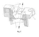
- FIG. 2 is a longitudinal sectional view of a fixation base according to the embodiment of the present invention.
- FIG. 3 is a schematic structural diagram of the fixation bases, standard microphones and a fixation scaffold in separated state according to the embodiment of the present invention
- FIG. 4 is a schematic structural diagram of clip devices and the fixation scaffold in separated state according to the embodiment of the present invention.
- FIG. 5 shows a structure of sealers in the fixation bases according to the embodiment of the present invention
- FIG. 6 is a schematic longitudinal cross-sectional structural diagram of the sealer and the standard microphone when the standard microphone and the fixation base are attached according to the embodiment of the present invention
- FIG. 7 is an entire structural diagram in which earphones are placed in the earphone testing device according to the embodiment of the present invention.
- the earphone testing device comprises a fixation base, a standard microphone attached to the fixation base, and a fixation scaffold for attaching and fixing the fixation base and the standard microphone; the fixation base is supported and fixed on the fixation scaffold by several supporting elements;
- a sealer is located on the position on the fixation base in contact with the outer shell of an earphone, the sealer forms an earphone storage portion for placing the earphone;
- a sealer is located on the position on the fixation base in contact with the outer shell of standard microphone, the sealer forms a microphone attachment portion for attaching to the standard microphone;
- the earphone placed in the earphone storage portion and the standard microphone attached onto the microphone attachment portion are communicated with each other in the fixation base.
- a pass-through portion is provided in the fixation base and passes through the fixation base; the earphone storage portion is located on the fixation base and in the pass-through portion, the microphone attachment portion is located on the fixation base and in the pass-through portion, and the earphone placed in the earphone storage portion is communicated with the standard microphone attached onto the microphone attachment portion through the pass-through portion in the fixation base.
- the pass-through portion can be formed by removing material in the fixation base.
- the sealer may be elastomeric structure.
- the earphone storage portion is formed above the fixation base but is not restricted thereby, and the microphone attachment portion is formed below the fixation base but is not restricted thereby.
- the earphone testing device by the earphone storage portion in contact with the outer shell of earphone and the microphone attachment portion in contact with the outer shell of the standard microphone formed by the sealer, is able to prevent sound leaking, guarantee the tightness of the earphone testing device, thus improve the precision of testing result; furthermore, the present solution guarantees the balance of fixation base through supporting elements and the fixation scaffold, to improve the stability of the testing result of earphone.
- FIG. 1 shows the entire structure of the earphone testing device after assembly.
- the earphone testing device comprises fixation base 1 and a fixation scaffold 2
- the fixation base 1 in this embodiment comprise the fixation base of left earphone and the fixation base of right earphone
- the fixation base of left earphone and the fixation base of right earphone are symmetry in structure.
- the fixation base 1 (such as the fixation base of left earphone or the fixation base of right earphone) is fixed on fixation scaffold 2 by several supporting columns 10 , a standard microphone 3 is attached to the lower side of the fixation base 1 , wherein the sensitivity and frequency response of the standard microphone 3 have been calibrated precisely, and the standard microphone 3 performs test by receiving the sound output from an earphone.
- a pass-through portion is formed passing through the fixation base (not illustrated in FIG. 1 ), and the sound communication between the earphone and the standard microphone is achieved by the pass-through portion.
- a sealer is provided on the position on the upper side of the fixation base 1 in contact with the outer shell of the earphone.
- the sealer is silicone rubber material
- the sealer is integrally formed with the fixation base 1
- the sealer is provided with an earphone storage portion for placing the earphone.
- a sealer is provided on the position on the lower side of the fixation base 1 in contact with the standard microphone and integrally formed with the fixation base 1
- the sealer is a microphone attachment portion for attaching to the standard microphone 3 .
- the sealer is partially formed in the region of the pass-through portion in the fixation base 1 , partially formed on the fixation base 1 (such as on the inner wall of the fixation base 1 in which material is removed, and on the outer surface of the fixation base 1 ), the earphone storage portion has a homologous shape as that of the earphone shell body placed in the earphone storage portion, and when the earphone is placed in the earphone storage portion, the sealer can come into contact with the outer shell of earphone tightly, carry on tight sealing effectively, and prevent sound leaking. Furthermore, the sealer can prevent damage to the outer shell of the earphone during testing, to ensure the outer shell of the earphone safe and intact.
- the sealer being the earphone storage portion is partially formed on the area of pass-through portion in the fixation base 1 , partially formed on the fixation base 1 (such as on the inner wall of the fixation base 1 in which material is removed, and on the outer surface of the fixation base 1 ), so that when the standard microphone 3 is attached to the microphone attachment portion, the sealer can come into contact with the outer shell of the standard microphone tightly, carry on tight sealing effectively, and prevent sound leaking. Furthermore, the sealer can prevent damage to the standard microphone 3 during testing, to ensure the outer shell of the standard microphone 3 safe.
- the earphone testing device illustrated in the FIG. 1 further comprises a clip device 4 , and the details of the structure of the clip device 4 will be mentioned correspondingly in the following description of the embodiment.
- FIG. 2 shows the longitudinal cross-sectional view of the fixation base 1 , wherein, the pass-through portion of the fixation base 1 is a hollowed region in a top-bottom direction (indicated by an arrow symbol) in the middle part of the fixation base 1 .
- the grid marked region in FIG. 2 is a cross-section of the sealer. It is seen from FIG. 2 that the sealer in the fixation base 1 in this embodiment is partially formed in the region of the pass-through portion in the fixation base 1 , partially formed on the fixation base 1 .
- the earphone storage portion 16 The upper part of the sealer in contact with the outer shell of the earphone forms the earphone storage portion 16 , the lower part of the sealer in contact with the standard microphone forms the microphone attachment portion 17 .
- the earphone storage portion 16 and the microphone attachment portion 17 in this embodiment are achieved by an integrally formed sealer.
- FIG. 3 is a schematic structural diagram of the fixation bases, the standard microphones and the fixation scaffold in separated state.
- the hollowed region in the middle part of the fixation base 1 is a pass-through portion
- the top part of the fixation base 1 has a plate-shaped flange 11 extending outwards from the fixation base
- several mounting holes 12 are arranged on the plate-shaped flange 11
- mounting holes 21 are arranged on the positions on fixation scaffold 2 corresponding to the mounting holes 12 .
- each of the several supporting columns 10 with same length is fixed to the mounting hole 12 of the plate-shaped flange 11 , and the other end is fixed to the mounting hole 21 of the fixation scaffold 2 .
- the number of the supporting columns 10 may be 4.
- the supporting column 10 is in a hollow tubular structure, and when individual components are assembled together, bolts pass through the hollow supporting columns 10 , the mounting holes 12 and the mounting holes 21 , and then are fixed by nuts, thus fixation base 1 and the fixation scaffold 2 are combined fixedly.
- the fixation base 1 is attached onto the fixation scaffold 2 evenly and horizontally, the change of the chamber caused by height difference can be avoided, thus guarantee the precision and stability of testing result.
- a pass-through hole 22 is provided on the position on the fixation scaffold 2 mounting the fixation base 1 , the standard microphone 3 passes through the fixation scaffold 2 from the pass-through hole 22 , and is attached to the microphone attachment portion 13 on the fixation base 1 .
- the standard microphone 3 is attached to the fixation base through the scaffold, so the standard microphone 3 is only required to be screwed out to be calibrated during calibration, and the entire testing device is unnecessary to be detached, thus improving the flexibility of the structure of testing device, and facilitating the operation for testing.
- the testing device of this embodiment further comprises a clip device 4 (referring to FIG. 1 ), which fixes the earphone from the upper side of the earphone when the earphone is placed in the earphone storage portion 16 , so that the left and right earphones are respectively retained in suitable, consistent positions in the fixation base of left earphone and the fixation base of right earphone, ensuring the consistency of testing result of left and right earphones.
- the clip device 4 makes earphone not mobile randomly during testing, further guarantees the precision and stability of testing.
- FIG. 4 it shows the structural diagram of clip device 4 and fixation scaffold 2 in separated state.
- Clip device 4 is installed on the fixation scaffold 2 , and the clip head 40 of clip device 4 corresponds to the position of the earphone storage portion.
- the clip head 40 of clip device 4 presses the earphone in the earphone storage portion tightly.
- the clip device 4 comprises a clip body support 41 and a clip body 42 above the clip body support 41 , one end of the clip body 42 is provided with a hole for installing the clip head 40 , the clip head 40 in this embodiment is made of soft material, such as rubber or silicone, is able to make earphone after placed in the chamber is in contact with the chamber very tightly, prevent sound leaking, and improve the precision of testing.
- the clip body support 41 is provided with mounting holes 410
- the clip body 42 is provided with mounting holes 420
- the fixation, scaffold 2 is provided with mounting holes 23 respectively in the position for mounting the clip device 4 ;
- FIG. 1 Several supporting columns 10 (referring to FIG. 1 ) fixe clip device 4 and fixation scaffold 2 together by passing through the mounting holes 410 of the clip body 42 , the mounting holes 420 of the clip body support 41 and the mounting holes 23 of the fixation scaffold 2 .
- the fixation base in the embodiment of the present invention can be made, of material with a rather high hardness such as stainless steel etc., after the fixation base is formed, the material inside of the fixation base is removed (hollowed) to form a pass-through portion, then by use of mold and melted colloidal material, the sealer comprising an earphone storage portion and a microphone attachment portion is formed integrally.
- the sealer comprising an earphone storage portion and a microphone attachment portion is formed integrally.
- several channels can be provided in the fixation base for flowing channel and formation of melted colloidal material. Referring to FIG.
- FIG. 5 shows the structure of integrated sealer of the earphone storage portion 16 and the microphone attachment portion 17 in the fixation base, in which, to make the structure of the sealer clearer, the structure of sealer is shown independently; however, with regards to an actual testing device, the sealer and the fixation base are integrated and inseparable.
- FIG. 5 shows the sealer in the fixation base of left earphone (with a L label) and the fixation base of right earphone (with a R label), these two sealers are symmetrical in structure, whose internal hollowed part (for communicating the earphone with the standard microphone) constructs the chamber for a testing earphone (the chamber is formed in the pass-through portion).
- the top end of earphone storage portion exemplified in FIG. 5 covers the corresponding position of the top part of fixation base.
- a groove 14 is provided, on the earphone storage portion for placing an earphone handle, the groove 14 is benefit for fixing the location of earphone and making the earphone fit the earphone storage portion perfectly.
- the fixation base in this embodiment is provided with a sound leaking trough 15 , the position of the sound leaking trough 15 corresponds to the position of leaking hole on the earphone placed in the earphone storage portion. That is, the earphone has a leaking hole directing to the chamber, and after the earphone is placed in the earphone storage portion, the leaking hole of the earphone corresponds to the sound leaking trough 15 .
- the sound leaking trough 15 not only makes earphone fit to the fixation base, but also prevents the occurrence of resonance phenomenon of chamber, which affects testing result.
- One manner of providing the sound leaking trough 15 is making the direction of sound leaking trough 15 vertical to the sound broadcasting direction in the chamber.
- the leaking hole 15 in FIG. 5 is an example, the leaking hole 15 is provided on top of the earphone storage portion (the fixation base).
- FIG. 6 it is a schematic diagram of longitudinal cross-section of the sealer and the standard microphone, which shows the schematic structure of longitudinal cross-section when the standard microphone and the fixation base are attached, and does not show the stainless steel part on the periphery of the fixation base, grid marked part in the upper part of cross view is the cross section part of the sealer in fixation base (comprising the earphone storage portion 16 and the microphone attachment portion 17 ).
- the part of sealer above the dashed line in the figure can be deemed as the earphone storage portion 16
- the part of sealer below the dashed line in the figure can be deemed as the microphone attachment portion 17 .
- FIG. 7 it shows the entire structural figure of placing an earphone in the earphone testing device. It is seen from FIG. 7 that, the earphone 5 is placed in the earphone storage portion, the clip head 40 of the clip device 4 is clamped on the earphone 5 , so that the earphone 5 is stabilized in an appropriate position in the earphone storage portion, and is in contact with the earphone storage portion tightly.
- the earphone handle 50 of earphone 5 is placed in the groove 14 on the earphone storage portion of fixation base 1 for placing the earphone handle.
- the standard microphone 3 passes through the hole on the fixation scaffold 2 , and is attached to the microphone attachment portion in the fixation base 1 .
- the earphone testing device provided by the present solution (comprising the fixation base of left earphone and the fixation base of right earphone)
- the consistency of testing result of left and right earphones is maintained within 0.2 DB, a GRR (Gauge Repeatability and Reproducibility) below 10%.
- the earphone testing device provided by the embodiments of the present invention, by use of the earphone storage portion in contact with the outer shell of an earphone and the microphone attachment portion in contact with the outer shell of a standard microphone formed by a sealer, is able to prevent sound leaking, guarantee the tightness of earphone testing device, thus improve the precision of testing result; furthermore, the present solution guarantees the stationarity of the fixation base by the supporting columns and the fixation scaffold, improves the stability of the testing result of earphone.
Landscapes
- Signal Processing (AREA)
- Physics & Mathematics (AREA)
- Engineering & Computer Science (AREA)
- Acoustics & Sound (AREA)
- General Health & Medical Sciences (AREA)
- Otolaryngology (AREA)
- Health & Medical Sciences (AREA)
- Details Of Audible-Bandwidth Transducers (AREA)
- Investigating Strength Of Materials By Application Of Mechanical Stress (AREA)
- Measurement Of Mechanical Vibrations Or Ultrasonic Waves (AREA)
- Headphones And Earphones (AREA)
- Examining Or Testing Airtightness (AREA)
- Investigating Or Analyzing Materials By The Use Of Ultrasonic Waves (AREA)
Applications Claiming Priority (4)
| Application Number | Priority Date | Filing Date | Title |
|---|---|---|---|
| CN201210381149 | 2012-10-09 | ||
| CN201210381149.XA CN102857853B (zh) | 2012-10-09 | 2012-10-09 | 耳机测试装置 |
| CN201210381149.X | 2012-10-09 | ||
| PCT/CN2013/081985 WO2014056355A1 (zh) | 2012-10-09 | 2013-08-21 | 耳机测试装置 |
Publications (2)
| Publication Number | Publication Date |
|---|---|
| US20150264501A1 US20150264501A1 (en) | 2015-09-17 |
| US9503827B2 true US9503827B2 (en) | 2016-11-22 |
Family
ID=47403978
Family Applications (1)
| Application Number | Title | Priority Date | Filing Date |
|---|---|---|---|
| US14/432,412 Active 2033-10-20 US9503827B2 (en) | 2012-10-09 | 2013-08-21 | Earphone testing device |
Country Status (7)
| Country | Link |
|---|---|
| US (1) | US9503827B2 (de) |
| EP (1) | EP2887699B1 (de) |
| JP (1) | JP5861013B2 (de) |
| KR (1) | KR101528724B1 (de) |
| CN (1) | CN102857853B (de) |
| DK (1) | DK2887699T3 (de) |
| WO (1) | WO2014056355A1 (de) |
Cited By (1)
| Publication number | Priority date | Publication date | Assignee | Title |
|---|---|---|---|---|
| US12495259B2 (en) | 2021-06-14 | 2025-12-09 | Ams-Osram Ag | Earphone coupler |
Families Citing this family (56)
| Publication number | Priority date | Publication date | Assignee | Title |
|---|---|---|---|---|
| CN102857853B (zh) * | 2012-10-09 | 2014-10-29 | 歌尔声学股份有限公司 | 耳机测试装置 |
| CN103096237B (zh) * | 2013-02-19 | 2015-06-24 | 歌尔声学股份有限公司 | 用于线控耳机组装和测试的多功能装置 |
| JP6202744B2 (ja) | 2014-01-15 | 2017-09-27 | 株式会社タダノ | 油圧アクチュエータの速度制御装置 |
| KR101518867B1 (ko) * | 2014-05-09 | 2015-05-13 | 시그마엘텍(주) | 이어셋 검사장치용 셋팅지그 및 이어셋 검사장치 |
| CN105704631A (zh) * | 2014-11-24 | 2016-06-22 | 西格玛艾尔科技股份有限公司 | 耳机在线检查方法 |
| US9854372B2 (en) * | 2015-08-29 | 2017-12-26 | Bragi GmbH | Production line PCB serial programming and testing method and system |
| US9949008B2 (en) | 2015-08-29 | 2018-04-17 | Bragi GmbH | Reproduction of ambient environmental sound for acoustic transparency of ear canal device system and method |
| US9949013B2 (en) | 2015-08-29 | 2018-04-17 | Bragi GmbH | Near field gesture control system and method |
| US9972895B2 (en) | 2015-08-29 | 2018-05-15 | Bragi GmbH | Antenna for use in a wearable device |
| US9843853B2 (en) | 2015-08-29 | 2017-12-12 | Bragi GmbH | Power control for battery powered personal area network device system and method |
| US9905088B2 (en) | 2015-08-29 | 2018-02-27 | Bragi GmbH | Responsive visual communication system and method |
| US10104458B2 (en) | 2015-10-20 | 2018-10-16 | Bragi GmbH | Enhanced biometric control systems for detection of emergency events system and method |
| US9980189B2 (en) | 2015-10-20 | 2018-05-22 | Bragi GmbH | Diversity bluetooth system and method |
| US9866941B2 (en) | 2015-10-20 | 2018-01-09 | Bragi GmbH | Multi-point multiple sensor array for data sensing and processing system and method |
| US9939891B2 (en) | 2015-12-21 | 2018-04-10 | Bragi GmbH | Voice dictation systems using earpiece microphone system and method |
| US9980033B2 (en) | 2015-12-21 | 2018-05-22 | Bragi GmbH | Microphone natural speech capture voice dictation system and method |
| US10085091B2 (en) | 2016-02-09 | 2018-09-25 | Bragi GmbH | Ambient volume modification through environmental microphone feedback loop system and method |
| US10085082B2 (en) | 2016-03-11 | 2018-09-25 | Bragi GmbH | Earpiece with GPS receiver |
| US10045116B2 (en) | 2016-03-14 | 2018-08-07 | Bragi GmbH | Explosive sound pressure level active noise cancellation utilizing completely wireless earpieces system and method |
| US10052065B2 (en) | 2016-03-23 | 2018-08-21 | Bragi GmbH | Earpiece life monitor with capability of automatic notification system and method |
| CN105704635B (zh) * | 2016-03-31 | 2019-11-15 | 歌尔股份有限公司 | 麦克风振动测试治具 |
| US10015579B2 (en) | 2016-04-08 | 2018-07-03 | Bragi GmbH | Audio accelerometric feedback through bilateral ear worn device system and method |
| US10013542B2 (en) | 2016-04-28 | 2018-07-03 | Bragi GmbH | Biometric interface system and method |
| US10201309B2 (en) | 2016-07-06 | 2019-02-12 | Bragi GmbH | Detection of physiological data using radar/lidar of wireless earpieces |
| US10045110B2 (en) | 2016-07-06 | 2018-08-07 | Bragi GmbH | Selective sound field environment processing system and method |
| US10062373B2 (en) | 2016-11-03 | 2018-08-28 | Bragi GmbH | Selective audio isolation from body generated sound system and method |
| US10205814B2 (en) | 2016-11-03 | 2019-02-12 | Bragi GmbH | Wireless earpiece with walkie-talkie functionality |
| US10063957B2 (en) | 2016-11-04 | 2018-08-28 | Bragi GmbH | Earpiece with source selection within ambient environment |
| US10045112B2 (en) | 2016-11-04 | 2018-08-07 | Bragi GmbH | Earpiece with added ambient environment |
| US10045117B2 (en) | 2016-11-04 | 2018-08-07 | Bragi GmbH | Earpiece with modified ambient environment over-ride function |
| US10058282B2 (en) | 2016-11-04 | 2018-08-28 | Bragi GmbH | Manual operation assistance with earpiece with 3D sound cues |
| US10506327B2 (en) | 2016-12-27 | 2019-12-10 | Bragi GmbH | Ambient environmental sound field manipulation based on user defined voice and audio recognition pattern analysis system and method |
| US10405081B2 (en) | 2017-02-08 | 2019-09-03 | Bragi GmbH | Intelligent wireless headset system |
| US10582290B2 (en) | 2017-02-21 | 2020-03-03 | Bragi GmbH | Earpiece with tap functionality |
| US10771881B2 (en) | 2017-02-27 | 2020-09-08 | Bragi GmbH | Earpiece with audio 3D menu |
| US10575086B2 (en) | 2017-03-22 | 2020-02-25 | Bragi GmbH | System and method for sharing wireless earpieces |
| US11544104B2 (en) | 2017-03-22 | 2023-01-03 | Bragi GmbH | Load sharing between wireless earpieces |
| US11694771B2 (en) | 2017-03-22 | 2023-07-04 | Bragi GmbH | System and method for populating electronic health records with wireless earpieces |
| US11380430B2 (en) | 2017-03-22 | 2022-07-05 | Bragi GmbH | System and method for populating electronic medical records with wireless earpieces |
| US10708699B2 (en) | 2017-05-03 | 2020-07-07 | Bragi GmbH | Hearing aid with added functionality |
| US11116415B2 (en) | 2017-06-07 | 2021-09-14 | Bragi GmbH | Use of body-worn radar for biometric measurements, contextual awareness and identification |
| US11013445B2 (en) | 2017-06-08 | 2021-05-25 | Bragi GmbH | Wireless earpiece with transcranial stimulation |
| US10344960B2 (en) | 2017-09-19 | 2019-07-09 | Bragi GmbH | Wireless earpiece controlled medical headlight |
| US11272367B2 (en) | 2017-09-20 | 2022-03-08 | Bragi GmbH | Wireless earpieces for hub communications |
| CN110830903B (zh) * | 2018-08-10 | 2021-08-27 | 惠州迪芬尼声学科技股份有限公司 | 测试机 |
| CN108712709A (zh) * | 2018-08-15 | 2018-10-26 | 会听声学科技(北京)有限公司 | 降噪耳机测试装置及系统、其麦克风故障诊断装置、系统及方法 |
| CN111800724B (zh) * | 2019-12-31 | 2022-03-22 | 深圳市豪恩声学股份有限公司 | 一种入耳式耳机佩戴检测装置和方法 |
| US11451893B2 (en) * | 2020-02-06 | 2022-09-20 | Audix Corporation | Integrated acoustic coupler for professional sound industry in-ear monitors |
| CN112135235B (zh) * | 2020-09-22 | 2022-05-24 | 歌尔科技有限公司 | 质量检测方法、系统及计算机可读存储介质 |
| CN112135237B (zh) * | 2020-09-27 | 2021-11-09 | 惠州市克林声学有限公司 | 耳机声学检测装置及设备 |
| CN112104970B (zh) * | 2020-10-29 | 2021-11-30 | 深圳市微测检测有限公司 | 一种用于无线耳机开机检测自动化装置 |
| CN112448216B (zh) * | 2020-11-17 | 2022-05-17 | Oppo(重庆)智能科技有限公司 | 耳机座、终端及其气密性检测方法和耳机座组件 |
| CN112770245A (zh) * | 2020-12-29 | 2021-05-07 | 华勤技术股份有限公司 | 检测装置以及测试方法 |
| CN113267293A (zh) * | 2021-05-19 | 2021-08-17 | 深圳市美格信测控技术有限公司 | 无线耳机的麦克风气密性测试装置 |
| CN116249060A (zh) * | 2022-12-20 | 2023-06-09 | 立讯电子科技(昆山)有限公司 | 一种光学检测耳机用的调节装置、检测设备及检测方法 |
| CN118075677B (zh) * | 2024-04-19 | 2024-06-21 | 深圳市汇杰芯科技有限公司 | 一种耳机插拔检测设备 |
Citations (4)
| Publication number | Priority date | Publication date | Assignee | Title |
|---|---|---|---|---|
| US4038500A (en) | 1975-06-20 | 1977-07-26 | Frye George J | Microphone coupler |
| US20090122996A1 (en) | 2007-11-11 | 2009-05-14 | Source Of Sound Ltd. | Earplug sealing test |
| CN102572671A (zh) | 2010-12-20 | 2012-07-11 | 歌尔声学股份有限公司 | 麦克风密封性测试方法、测试工装以及测试系统 |
| US8977376B1 (en) * | 2014-01-06 | 2015-03-10 | Alpine Electronics of Silicon Valley, Inc. | Reproducing audio signals with a haptic apparatus on acoustic headphones and their calibration and measurement |
Family Cites Families (11)
| Publication number | Priority date | Publication date | Assignee | Title |
|---|---|---|---|---|
| GB2279760B (en) * | 1993-07-06 | 1997-04-23 | Gentex Corp | Communication headset tester |
| CA2187472A1 (en) * | 1995-10-17 | 1997-04-18 | Frank S. Cheng | System and method for testing communications devices |
| JP2007221511A (ja) * | 2006-02-17 | 2007-08-30 | Nobuhiko Ido | 再生音の採音機能を備えた受話器、採音した再生音の記録機能を備えた音声再生装置、および、録音した音声の内容を解析する音声信号処理装置 |
| CN201118985Y (zh) * | 2007-08-28 | 2008-09-17 | 富声(东莞)电器配件有限公司 | 一种耳机麦克风杆转动寿命试验机 |
| KR100868972B1 (ko) * | 2008-04-25 | 2008-11-17 | 주식회사 소비코 | 휴대용 마이크로 스피커 테스트 박스 |
| JP5281968B2 (ja) * | 2009-06-30 | 2013-09-04 | 株式会社オーディオテクニカ | ダイナミックマイクロホンユニットの音響特性測定方法 |
| CN102026083A (zh) * | 2009-09-16 | 2011-04-20 | 沈阳晨讯希姆通科技有限公司 | 耳机测试装置 |
| CN201967131U (zh) * | 2010-12-27 | 2011-09-07 | 亚光耐普罗精密注塑(天津)有限公司 | 手机电声测试夹具 |
| CN201995130U (zh) * | 2011-03-16 | 2011-09-28 | 廖光鸿 | 喇叭音质检测装置 |
| CN202957980U (zh) * | 2012-10-09 | 2013-05-29 | 歌尔声学股份有限公司 | 耳机测试装置 |
| CN102857853B (zh) * | 2012-10-09 | 2014-10-29 | 歌尔声学股份有限公司 | 耳机测试装置 |
-
2012
- 2012-10-09 CN CN201210381149.XA patent/CN102857853B/zh active Active
-
2013
- 2013-08-21 KR KR1020157006376A patent/KR101528724B1/ko active Active
- 2013-08-21 JP JP2015534901A patent/JP5861013B2/ja active Active
- 2013-08-21 US US14/432,412 patent/US9503827B2/en active Active
- 2013-08-21 EP EP13844853.5A patent/EP2887699B1/de active Active
- 2013-08-21 WO PCT/CN2013/081985 patent/WO2014056355A1/zh not_active Ceased
- 2013-08-21 DK DK13844853.5T patent/DK2887699T3/en active
Patent Citations (4)
| Publication number | Priority date | Publication date | Assignee | Title |
|---|---|---|---|---|
| US4038500A (en) | 1975-06-20 | 1977-07-26 | Frye George J | Microphone coupler |
| US20090122996A1 (en) | 2007-11-11 | 2009-05-14 | Source Of Sound Ltd. | Earplug sealing test |
| CN102572671A (zh) | 2010-12-20 | 2012-07-11 | 歌尔声学股份有限公司 | 麦克风密封性测试方法、测试工装以及测试系统 |
| US8977376B1 (en) * | 2014-01-06 | 2015-03-10 | Alpine Electronics of Silicon Valley, Inc. | Reproducing audio signals with a haptic apparatus on acoustic headphones and their calibration and measurement |
Non-Patent Citations (2)
| Title |
|---|
| CN 201210381149.X, Notice of Decision of Granting Patent For Invention, dated Aug. 22, 2014, 1 page, and English Translation, 2 pages. |
| CN 201210381149.X, The First Office Action, dated May 26, 2014, 8 pages, and English Translation, 8 pages. |
Cited By (1)
| Publication number | Priority date | Publication date | Assignee | Title |
|---|---|---|---|---|
| US12495259B2 (en) | 2021-06-14 | 2025-12-09 | Ams-Osram Ag | Earphone coupler |
Also Published As
| Publication number | Publication date |
|---|---|
| KR101528724B1 (ko) | 2015-06-12 |
| JP5861013B2 (ja) | 2016-02-16 |
| EP2887699B1 (de) | 2016-08-03 |
| EP2887699A4 (de) | 2015-07-15 |
| EP2887699A1 (de) | 2015-06-24 |
| WO2014056355A1 (zh) | 2014-04-17 |
| CN102857853B (zh) | 2014-10-29 |
| US20150264501A1 (en) | 2015-09-17 |
| CN102857853A (zh) | 2013-01-02 |
| KR20150038646A (ko) | 2015-04-08 |
| JP2015530853A (ja) | 2015-10-15 |
| DK2887699T3 (en) | 2016-11-21 |
Similar Documents
| Publication | Publication Date | Title |
|---|---|---|
| US9503827B2 (en) | Earphone testing device | |
| WO2016150197A1 (zh) | 振膜组件及设有该振膜组件的扬声器 | |
| CN110834283A (zh) | 一种五合一膜电极封装夹具和质子交换膜燃料电池 | |
| CN216017164U (zh) | 一种通用型耳机声学测试固定架 | |
| CN206559640U (zh) | 一种组合式双频喇叭 | |
| CN202957980U (zh) | 耳机测试装置 | |
| CN108857981B (zh) | 产品定位装置及定位方法 | |
| WO2021109195A1 (zh) | 扬声器单体的声学测试密封结构 | |
| CN207753849U (zh) | 无源辐射器及具有其的音箱 | |
| CN204993866U (zh) | 一种耳承测试工装用固定支架 | |
| CN107631862B (zh) | 带光纤式y波导器件离心试验夹具 | |
| CN207491193U (zh) | 一种音圈 | |
| CN205147364U (zh) | 一种油压涨紧夹具 | |
| CN204810545U (zh) | 一种动铁喇叭和动圈喇叭的组合结构及耳机 | |
| CN222866143U (zh) | 一种用于扬声器前腔的气密性测试工装 | |
| CN203057488U (zh) | 传声器极头高频离轴响应轴向对称结构 | |
| CN205283796U (zh) | 一种喇叭及带有喇叭的出音装置 | |
| CN219178601U (zh) | 一种便于固定的检测探头 | |
| CN220359355U (zh) | 一种扬声器 | |
| CN206406310U (zh) | 方形耳机套定型治具 | |
| CN213658217U (zh) | 一种单路旋流器空气流量试验装置 | |
| CN207354530U (zh) | 一种超薄音响 | |
| CN210351607U (zh) | 一种音圈音膜固定装置 | |
| CN210817307U (zh) | 一种四缸机治具 | |
| CN113809642B (zh) | 复合离子发生的装置及其方法 |
Legal Events
| Date | Code | Title | Description |
|---|---|---|---|
| AS | Assignment |
Owner name: GOERTEK, INC., CHINA Free format text: ASSIGNMENT OF ASSIGNORS INTEREST;ASSIGNORS:HU, ZONGBAO;ZHENG, WENTUAN;SONG, BAOHUI;AND OTHERS;REEL/FRAME:035589/0954 Effective date: 20150421 |
|
| STCF | Information on status: patent grant |
Free format text: PATENTED CASE |
|
| MAFP | Maintenance fee payment |
Free format text: PAYMENT OF MAINTENANCE FEE, 4TH YEAR, LARGE ENTITY (ORIGINAL EVENT CODE: M1551); ENTITY STATUS OF PATENT OWNER: LARGE ENTITY Year of fee payment: 4 |
|
| MAFP | Maintenance fee payment |
Free format text: PAYMENT OF MAINTENANCE FEE, 8TH YEAR, LARGE ENTITY (ORIGINAL EVENT CODE: M1552); ENTITY STATUS OF PATENT OWNER: LARGE ENTITY Year of fee payment: 8 |