US9511792B2 - Steering device - Google Patents
Steering device Download PDFInfo
- Publication number
- US9511792B2 US9511792B2 US14/905,509 US201414905509A US9511792B2 US 9511792 B2 US9511792 B2 US 9511792B2 US 201414905509 A US201414905509 A US 201414905509A US 9511792 B2 US9511792 B2 US 9511792B2
- Authority
- US
- United States
- Prior art keywords
- resin
- pin
- collar
- plate
- hole
- Prior art date
- Legal status (The legal status is an assumption and is not a legal conclusion. Google has not performed a legal analysis and makes no representation as to the accuracy of the status listed.)
- Expired - Fee Related
Links
- 239000011347 resin Substances 0.000 claims abstract description 159
- 229920005989 resin Polymers 0.000 claims abstract description 159
- 230000000007 visual effect Effects 0.000 claims abstract description 103
- 230000007246 mechanism Effects 0.000 claims description 54
- 239000000725 suspension Substances 0.000 claims description 42
- 230000008878 coupling Effects 0.000 description 29
- 238000010168 coupling process Methods 0.000 description 29
- 238000005859 coupling reaction Methods 0.000 description 29
- 239000002783 friction material Substances 0.000 description 9
- 229920006324 polyoxymethylene Polymers 0.000 description 9
- 229930182556 Polyacetal Natural products 0.000 description 6
- 239000002184 metal Substances 0.000 description 6
- 229910052751 metal Inorganic materials 0.000 description 6
- 229920006122 polyamide resin Polymers 0.000 description 6
- 239000002775 capsule Substances 0.000 description 5
- 230000007547 defect Effects 0.000 description 5
- YCKRFDGAMUMZLT-UHFFFAOYSA-N Fluorine atom Chemical compound [F] YCKRFDGAMUMZLT-UHFFFAOYSA-N 0.000 description 3
- 239000000919 ceramic Substances 0.000 description 3
- 239000011737 fluorine Substances 0.000 description 3
- 229910052731 fluorine Inorganic materials 0.000 description 3
- XEEYBQQBJWHFJM-UHFFFAOYSA-N Iron Chemical compound [Fe] XEEYBQQBJWHFJM-UHFFFAOYSA-N 0.000 description 2
- 238000010008 shearing Methods 0.000 description 2
- 230000035939 shock Effects 0.000 description 2
- 238000010521 absorption reaction Methods 0.000 description 1
- 230000003466 anti-cipated effect Effects 0.000 description 1
- 238000006073 displacement reaction Methods 0.000 description 1
- 229910052742 iron Inorganic materials 0.000 description 1
- 238000004519 manufacturing process Methods 0.000 description 1
- 239000000463 material Substances 0.000 description 1
- 230000002093 peripheral effect Effects 0.000 description 1
Images




Classifications
-
- B—PERFORMING OPERATIONS; TRANSPORTING
- B62—LAND VEHICLES FOR TRAVELLING OTHERWISE THAN ON RAILS
- B62D—MOTOR VEHICLES; TRAILERS
- B62D1/00—Steering controls, i.e. means for initiating a change of direction of the vehicle
- B62D1/02—Steering controls, i.e. means for initiating a change of direction of the vehicle vehicle-mounted
- B62D1/16—Steering columns
- B62D1/18—Steering columns yieldable or adjustable, e.g. tiltable
- B62D1/19—Steering columns yieldable or adjustable, e.g. tiltable incorporating energy-absorbing arrangements, e.g. by being yieldable or collapsible
- B62D1/195—Yieldable supports for the steering column
-
- B—PERFORMING OPERATIONS; TRANSPORTING
- B62—LAND VEHICLES FOR TRAVELLING OTHERWISE THAN ON RAILS
- B62D—MOTOR VEHICLES; TRAILERS
- B62D1/00—Steering controls, i.e. means for initiating a change of direction of the vehicle
- B62D1/02—Steering controls, i.e. means for initiating a change of direction of the vehicle vehicle-mounted
- B62D1/16—Steering columns
- B62D1/18—Steering columns yieldable or adjustable, e.g. tiltable
- B62D1/187—Steering columns yieldable or adjustable, e.g. tiltable with tilt adjustment; with tilt and axial adjustment
- B62D1/189—Steering columns yieldable or adjustable, e.g. tiltable with tilt adjustment; with tilt and axial adjustment the entire column being tiltable as a unit
Definitions
- the present invention relates to a steering device.
- a secondary collision in which the driver collides with a steering wheel occurs.
- various structures in which a part of a steering column releases from the vehicle body, and is moved in the direction of the column shaft have been proposed.
- FIG. 9 of Patent Reference 1 for example, a pair of engaging cutouts which extend parallel to the direction of a column shaft are disposed in a vehicle body-side bracket fixed to the vehicle body.
- a column-side bracket is supported through a pair of engaging capsules which are held by a plurality of engaging pins, by the engaging cutouts respectively.
- the engaging capsules are coupled and fixed to the column-side bracket through bolts which are passed through the engaging cutouts, respectively.
- the plurality of engaging pins holding the engaging capsules are broken, whereby the engaging capsules are caused to release from the corresponding engaging cutouts, and the bolts, the engaging capsules, and the column bracket are caused to co-move with one another in the column shaft direction.
- Patent Reference 1 JP-A-2012-121538
- the inventors of the present application firstly considered that a slide plate which closes the upper side of a resin pin, and which, in a secondary collision, is moved in the movement direction of the column is disposed, and an elastic repulsion force is applied to the slide plate by an axial elastic projection disposed on the resin pin.
- a resin-pin visual check hole for visually checking a resin pin is disposed in a slide plate.
- the invention provides a steering device comprising: a stationary bracket which is fixed to a vehicle body-side member, and which includes a first plate in which a first resin-pin passing hole, and a first bolt passing hole configured by a long hole that extends in a column movement direction in a secondary collision are formed; a movable jacket which is configured to rotatably support a steering shaft in which a steering member is coupled to one end; a movable bracket which is configured to support the movable jacket in a manner that, in a secondary collision, the movable bracket is moved together with the movable jacket in the column movement direction, and which includes a second plate that is opposed to a lower surface of the first plate, the second plate in which a second resin-pin passing hole and a second bolt passing hole are formed; a suspension mechanism which includes: a slide plate in which a third bolt passing hole and a resin-pin visual check hole are formed along an upper surface of the first plate; and a suspension bolt which is passed sequentially through the third
- the axial elastic projection which directly or indirectly urges the slide plate is disposed at a position avoiding the range where, in a secondary collision, the resin-pin visual check hole passes in the column movement direction. Therefore, it is possible to, in a secondary collision, suppress the axial elastic projection of the resin pin from being caught in the resin-pin visual check hole. Consequently, an influence due to catching on the releasing load (increase of the releasing load) can be suppressed.
- the resin pin may include: a shaft portion which is passed through the collar; and a head flange which is coupled to one end of the shaft portion, the head flange may have: a first surface which is opposed to the slide plate; and a second surface which is opposed to an end surface of the collar, the elastic projection may be placed at a position avoiding the resin-pin visual check hole in the first surface of the head flange, and a rotation restricting convex portion which is disposed in at least one of the second surface of the head flange and the end surface of the collar may be fitted to a rotation restricting concave portion which is disposed on the other surface, thereby restricting relative rotation of the resin pin and the collar.
- the resin pin may include: a shaft portion which is passed through the collar; and a head flange which is coupled to one end of the shaft portion, an inner circumference of the first resin-pin passing hole may include a flat portion which is engaged with a flat portion disposed on an outer circumference of the head flange, thereby restricting rotation of the resin pin, the head flange may have: a first surface which is opposed to the slide plate; and a second surface which is opposed to an end surface of the collar, and the elastic projection may be placed at a position avoiding the resin-pin visual check hole in the first surface of the head flange.
- the resin pin may include: a shaft portion which is passed through the collar; and a head flange which is coupled to one end of the shaft portion, the head flange may have: a first surface which is opposed to the slide plate; and a second surface which is opposed to an end surface of the collar, and the elastic projection may be disposed on the second surface of the head flange.
- the head flange of the resin pin has the first surface which is opposed to the slide plate, and the second surface which is opposed to the collar, and the axial elastic projection is not disposed on the first surface, but disposed on the second surface.
- the catch of the axial elastic projection in the resin-pin visual check hole can never happen.
- the collar may include: a first collar which is placed in the first resin-pin passing hole, and which is press-fitted to the resin pin; and a second collar which is placed in the second resin-pin passing hole, and which is loose-fitted to the resin pin, and the elastic projection may be disposed on at least one of opposing surfaces the first collar and the second collar.
- the axial elastic projection is disposed on at least one of the opposing surfaces the first collar and the second collar. Therefore, the catch of the elastic projection in the resin-pin visual check hole can never happen.
- the resin-pin visual check hole may include a collar visual check region through which a part of the collar can be visually checked.
- FIG. 1 is a diagrammatic side view of a steering device of a first embodiment of the invention, and schematically shows the configuration of the steering device.
- FIG. 2 is a schematic sectional view of the steering device of the first embodiment, and shows a section taken along line II-II in FIG. 1 .
- FIG. 3 is an exploded perspective view of the steering device of the first embodiment.
- FIG. 4 is a partially cutaway schematic plan view of a stationary bracket, pair of suspension mechanisms, and coupling/decoupling mechanism in the first embodiment.
- FIG. 5 is a partially cutaway schematic plan view of the stationary bracket, pair of suspension mechanisms, and coupling/decoupling mechanism, and showing a partial cutaway of a slide plate in FIG. 4 .
- FIG. 6 is a partial enlarged view of FIG. 5 .
- FIG. 7 is an exploded perspective view of a resin pin and collar in the coupling/decoupling mechanism in the first embodiment.
- FIG. 8 is a sectional view of a coupled state of first and second plates in the first embodiment, and shows a section in the lateral direction (direction perpendicular to a column movement direction) including the axis of the resin pin.
- FIG. 9 is a sectional view of the coupled state of the first and second plates in the first embodiment, and shows a section in the anteroposterior direction (column movement direction) including the axis of the resin pin.
- FIG. 10 is a sectional view of the first and second plates in the first embodiment in a secondary collision, and shows a state where the second plate is caused to release from a predetermined position of the first plate in the column movement direction by sharing of the resin pin.
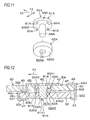
- FIG. 11 is an exploded perspective view of a resin pin and collar in a coupling/decoupling mechanism in a second embodiment of the invention.
- FIG. 12 is a sectional view of a coupled state of first and second plates in the second embodiment, and shows a section in the anteroposterior direction (column movement direction) including the axis of the resin pin.
- FIG. 13 is an exploded perspective view of a resin pin and collar in a coupling/decoupling mechanism in a third embodiment of the invention.
- FIG. 14 is a sectional view of a coupled state of first and second plates in the third embodiment, and shows a section in the anteroposterior direction (column movement direction) including the axis of the resin pin.
- FIG. 15 is an exploded perspective view of a slide plate, and a resin pin and collar in a coupling/decoupling mechanism in a fourth embodiment of the invention.
- FIG. 16 is a sectional view of a coupled state of first and second plates in the fourth embodiment, and shows a section in the lateral direction (direction perpendicular to a column movement direction) including the axis of the resin pin.
- FIG. 17 is a sectional view of a coupled state of first and second plates in a fifth embodiment of the invention, and shows a section in the lateral direction (direction perpendicular to a column movement direction) including the axis of a resin pin.
- FIG. 18 is a sectional view of a coupled state of first and second plates in a sixth embodiment of the invention, and shows a section in the lateral direction (direction perpendicular to a column movement direction) including the axis of a resin pin.
- FIG. 19 is a sectional view of a coupled state of first and second plates in a seventh embodiment of the invention, and shows a section in the lateral direction (direction perpendicular to a column movement direction) including the axis of a resin pin.
- FIG. 20 is a partially cutaway schematic plan view of a slide plate, and a resin pin and collar in a coupling/decoupling mechanism in an eighth embodiment of the invention.
- FIG. 1 is a diagrammatic view schematically showing the configuration of a steering device of a first embodiment of the invention.
- the steering device 1 includes: a steering shaft 3 which is coupled to a steering member 2 such as a steering wheel; an intermediate shaft 5 which is coupled to the steering shaft 3 through a universal joint 4 ; a pinion shaft 7 which is coupled to the intermediate shaft 5 through a universal joint 6 ; and a rack shaft 8 functioning as a steering shaft having a rack 8 a which meshes with a pinion 7 a disposed in the vicinity of an end portion of the pinion shaft 7 .
- a steering mechanism A 1 is configured by a rack and pinion mechanism including the pinion shaft 7 and the rack shaft 8 .
- the rack shaft 8 is supported by a housing 10 fixed to a vehicle body-side member 9 , so as to be movable in the axial direction (direction perpendicular to the sheet) extending along the lateral direction of a vehicle. End portions of the rack shaft 8 are not illustrated, but are connected to respective steered wheels through a corresponding tie rod and a corresponding knuckle arm.
- the steering shaft 3 has an upper shaft 11 and lower shaft 12 which are connected to each other by using, for example, a spline coupling so as to be co-rotatable and axially relatively movable.
- the steering shaft 3 is rotatably supported by a steering column 15 fixed to vehicle body-side members 13 , 14 , through a bearing which is not shown.
- the steering column 15 includes a tubular upper jacket 16 (movable jacket), and tubular lower jacket 17 which are fitted to each other so as to be axially relatively movable, and a housing 18 which is connected to the axial lower end of the lower jacket 17 .
- a reduction mechanism 20 which reduces the power of an electric motor 19 for assisting the steering, and which transmits the reduced power to the lower shaft 12 is housed in the housing 18 .
- the reduction mechanism 20 has a driving gear 21 which is co-rotatably coupled to a rotation shaft (not shown) of the electric motor 19 , and a driven gear 22 which meshes with the driving gear 21 to co-rotate with the lower shaft 12 .
- the invention may be applied also to a manual steering device.
- the embodiment will be described with reference to an example in which the steering device 1 is tilt-adjustable, the invention may be applied also to a steering device which is not provided with a tilt adjusting function, or that which is tilt-adjustable and telescopically adjustable.
- the steering device 1 includes the pair of suspension mechanisms T 1 , T 2 in which the upper jacket 16 is suspended by the stationary bracket 23 through the tilt bracket 24 functioning as the movable bracket.
- the tilt bracket 24 functioning as the movable bracket is suspended from the stationary bracket 23 fixed to the vehicle body-side member 13 , through suspension bolts 25 functioning as the suspension shafts of the pair of suspension mechanisms T 1 , T 2 .
- a column bracket 26 is fixed to the upper jacket 16 of the steering column 15 .
- the steering device 1 includes the locking mechanism 29 which, in accordance with an operation performed on an operation lever 27 , the position of the column bracket 26 which has undergone the tilt adjustment (therefore, the positions of the upper jacket 16 and the steering member 2 ) is locked or unlocked through the tilt bracket 24 by using a fastening shaft 28 .
- the tilt bracket 24 includes a pair of side plates 41 .
- the column bracket 26 has a groove-like shape including a pair of side plates 71 which are opposed to the pair of side plates 41 of the tilt bracket 24 , respectively, and a coupling plate 72 through which the lower ends of the pair of side plates 71 are coupled to each other.
- the fastening shaft 28 is configured by a bolt which is passed through the side plates 41 , 71 of the tilt bracket 24 and the column bracket 26 .
- a nut 73 screwed with the fastening shaft 28 is rotated by an operation of rotating the operation lever 27 , the side plates 41 , 71 are fastened together between the head of the bolt functioning as the fastening shaft 28 and the nut 73 , thereby locking the side plates 41 , 71 . Therefore, the position of the steering member 2 after the tilt adjustment is locked, and the tilt locking is accomplished.
- the steering device 1 includes a coupling/decoupling mechanism R 1 through which a first plate 30 of the stationary bracket 23 and a second plate 32 of the tilt bracket 24 are coupled to each other, and which, in a second collision, causes the second plate 32 to release from a predetermined position (position shown in FIG. 9 ) of the first plate 30 in a column movement direction X 1 as shown in FIG. 10 .
- the coupling/decoupling mechanism R 1 is placed between the pair of suspension mechanisms T 1 , T 2 (i.e., between a pair of first bolt passing holes 31 which will be described later, and which are in the first plate 30 of the stationary bracket 23 ) with respect to a direction Y 1 that is perpendicular to the column movement direction X 1 .
- the coupling/decoupling mechanism R 1 is placed in the middle position between the pair of first bolt passing holes 31 (i.e., between the pair of suspension bolts 25 ) with respect to the direction Y 1 that is perpendicular to the column movement direction X 1 .
- the stationary bracket 23 includes the first plate 30 which is parallel to the column movement direction X 1 (corresponding to the axial direction of the steering shaft 3 ) in a secondary collision.
- the first bolt passing holes 31 for the suspension mechanisms T 1 , T 2 and configured by long holes extending parallel to the column movement direction X 1 are formed.
- the tilt bracket 24 includes the second plate 32 which is opposed to the first plate 30 .
- second bolt passing holes 33 opposed to parts of the first bolt passing holes 31 , and for the suspension mechanisms T 1 , T 2 are formed.
- the suspension bolts 25 are configured by bolts which are passed through the first bolt passing holes 31 of the first plate 30 , and the second bolt passing holes 33 of the second plate 32 , and which are screwed with nuts 34 .
- the suspension bolts 25 which cooperate with the nuts 34 to couple the first plate 30 and the second plate 32 with each other suspend the upper jacket 16 (movable jacket) through the tilt bracket 24 (movable bracket) and the column bracket 26 .
- the suspension bolts 25 are movable in the column movement direction X 1 along the first bolt passing holes 31 together with the tilt bracket 24 (movable bracket), the column bracket 26 , and the upper jacket 16 .
- a lower bracket 35 which is fixed to the vehicle body-side member 14 supports a tilt center shaft 36 functioning as a pivot shaft.
- the tilt center shaft 36 supports the lower jacket 17 through the housing 18 of the steering column 15 , so as to be swingable about the tilt center shaft 36 .
- each of the suspension mechanisms T 1 , T 2 is configured by the suspension bolt 25 , a plate spring 42 formed by, for example, a disc spring, the nut 34 , and the like.
- the coupling/decoupling mechanism R 1 is configured by a resin pin 61 which is to be sheared in a secondary collision, and a collar 62 which is fitted to a part in the axial direction of the resin pin 61 , and in which the outer circumference is formed into a laterally elongated shape such as an oblong circular shape.
- a metal such as iron may be used, or a resin, ceramic, or the like which is higher in hardness than the resin pin 61 may be used.
- the resin pin 61 may be formed by polyacetal resin (POM), and the collar 62 may be formed by polyamide resin (PA) which is higher in hardness than polyacetal resin.
- the stationary bracket 23 includes a pair of side plates 37 which are downward extended from a pair of side edges of the first plate 30 , and a pair of attachment plates 38 which are extended outwardly and laterally from the pair of side plates 37 , respectively.
- the stationary bracket 23 is formed by, for example, sheet metal work.
- the attachment plates 38 are fixed to the vehicle body-side member 13 by fixing bolts 40 (see FIG. 4 ) which are passed through screw passing holes 39 (see FIGS. 3 and 4 ) disposed in the attachment plates 38 , respectively. As shown in FIG. 1 , therefore, the stationary bracket 23 is fixed to the vehicle body-side member 13 .
- the first bolt passing holes 31 are pairingly formed correspondingly with the pair of suspension bolts 25 .
- the pair of first bolt passing holes 31 extend parallel to the column movement direction X 1 in a secondary collision, and are separated from each other in the direction Y 1 that is perpendicular to the column movement direction X 1 .
- the tilt bracket 24 (movable bracket) is formed by, for example, sheet metal work.
- the tilt bracket 24 includes the second plate 32 , and a pair of side plates 41 which are downward extended from a pair of side edges of the second plate 32 , and is formed into a groove-like shape. As shown in FIGS. 2 and 3 , portions where the second plate 32 is coupled to the side plates 41 may be formed into an arcuate shape.
- the second bolt passing holes 33 are pairingly disposed correspondingly with the pair of suspension bolts 25 .
- Each of the suspension bolts 25 is sequentially passed through the annular plate spring 42 formed by, for example, a disc spring, a corresponding third bolt passing hole 44 of a slide plate 43 , the corresponding first bolt passing hole 31 of the first plate 30 , and the corresponding second bolt passing hole 33 of the second plate 32 , and then screwed with the nut 34 .
- the suspension bolts 25 suspend the tilt bracket 24 .
- the slide plate 43 is configured by a long plate which extends in the direction Y 1 that is perpendicular to the column movement direction X 1 , and, as shown in FIG. 2 , interposed between the plate springs 42 and the upper surface 30 a of the first plate 30 .
- the surface on the side of the first plate 30 is configured by a low-friction material such as a fluorine resin.
- the whole of the slide plate 43 may be configured by a low-friction material, or the surface of the slide plate 43 on the side of the first plate 30 may be covered with a low-friction material.
- a first interposed plate 45 and second interposed plate 46 which, in a secondary collision, reduce the sliding resistance in the movement of the second plate 32 in the column movement direction X 1 with respect to the first plate 30 are interposed between the first plate 30 and the second plate 32 .
- the first interposed plate 45 constitutes a groove-like unit 45 U which is engaged with a first end portion 321 that is an end portion in the column movement direction X 1 of the second plate 32 .
- the unit 45 U includes: the first interposed plate 45 which extends along the upper surface 32 a of the second plate 32 and the lower surface 30 b of the first plate 30 ; an opposing plate 47 which is opposed to the first interposed plate 45 , and which extends along the lower surface 32 b of the second plate 32 ; and a coupling plate 48 which couples the first interposed plate 45 with the opposing plate 47 , and which butts against the edge in the column movement direction X 1 of the second plate 32 .
- the first interposed plate 45 at least the surface on the side of the first plate 30 is configured by a low-friction material such as a fluorine resin.
- the first interposed plate 45 or the unit 45 U may be configured by a low-friction material, or the surface of the first interposed plate 45 on the side of the first plate 30 may be covered with a low-friction material.
- the second interposed plate 46 constitutes a unit 46 U which is engaged with a second end portion 302 that is an end portion of the first plate 30 opposite to the column movement direction X 1 , and a second end portion 322 that is an end portion of the second plate 32 opposite to the column movement direction X 1 .
- the unit 46 U includes the second interposed plate 46 which extends along the upper surface 32 a of the second plate 32 and the lower surface 30 b of the first plate 30 , and an opposing plate 49 which is opposed to the second interposed plate 46 , and which extends along the upper surface 30 a of the first plate 30 .
- the unit 46 U further includes a coupling plate 50 which couples the second interposed plate 46 with the opposing plate 49 , and which butts against the edge of the first plate 30 opposed to the column movement direction X 1 , and an engaging portion 51 which is to be hookingly engaged with the second end portion 322 of the second plate 32 , and which has, for example, a hook-like shape.
- the second interposed plate 46 at least the surface on the side of the second plate 32 is formed by a low-friction material such as a fluorine resin.
- a low-friction material such as a fluorine resin.
- the second interposed plate 46 or the unit 46 U may be formed by a low-friction material, or the surface of the second interposed plate 46 on the side of the second plate 32 may be covered with a low-friction material.
- each of the suspension bolts 25 includes: a head portion 52 ; a large-diameter portion 53 which is continuous to the head portion 52 , and which is smaller in diameter than the head portion 52 ; a small-diameter portion 54 which is continuous to the large-diameter portion 53 , and which is smaller in diameter than the large-diameter portion 53 ; a step portion 55 which is formed between the large-diameter portion 53 and the small-diameter portion 54 ; and a threaded portion 56 which is disposed in the small-diameter portion 54 .
- a tool engagement part 57 which has, for example, a hexagonal hole shape is disposed in the head portion 52 .
- the large-diameter portion 53 is passed through the annular plate spring 42 , the third bolt passing hole 44 of the slide plate 43 , and the first bolt passing hole 31 of the first plate 30 .
- the step portion 55 butts against the upper surface 32 a of the second plate 32 to be received by the upper surface 32 a .
- the second plate 32 is pressingly held between the step portion 55 and the nut 34 , and the suspension bolts 25 and the second plate 32 are fixed.
- the distance H 1 (corresponding to the shaft length of the large-diameter portion 53 ) between the head portion 52 and the step portion 55 is made larger than the total of the thickness of the first interposed plate 45 (or that of the second interposed plate 46 ) which is interposed between the first plate 30 and the second plate 32 , that of the first plate 30 , that of the slide plate 43 which extends along the upper surface 30 a of the first plate 30 , and that of the plate springs 42 in the most compressed state. Therefore, the plate springs 42 elastically urges the first plate 30 toward the second plate 32 through the slide plate 43 .
- the resin pin 61 of the first plate 30 , and for the coupling/decoupling mechanism R 1 is placed in the middle position between the first bolt passing holes 31 for the suspension mechanisms T 1 , T 2 with respect to the direction Y 1 that is perpendicular to the column movement direction X 1 . That is, the resin pin 61 is placed in the middle position between the pair of suspension bolts 25 with respect to the direction Y 1 that is perpendicular to the column movement direction X 1 .
- the first resin-pin passing hole 66 of the first plate 30 , and for the coupling/decoupling mechanism R 1 is formed into a laterally long hole which extends in the direction Y 1 that is perpendicular to the column movement direction X 1 . Therefore, gaps S 1 , S 2 are disposed between the outer circumference of the collar 62 and the inner circumference of the first resin-pin passing hole 66 with respect to the direction Y 1 that is perpendicular to the column movement direction X 1 .
- the resin pin 61 of the coupling/decoupling mechanism R 1 includes a head flange 63 which has, for example, a circular section, and a columnar shaft portion 64 which is smaller in diameter than the head flange 63 .
- the slide plate 43 is placed so as to cover the upper side of the head flange 63 of the resin pin 61 , thereby preventing the resin pin 61 from upwardly slipping off.
- a resin-pin visual check hole 65 which is smaller than the outer diameter of the head flange 63 of the resin pin 61 is formed so as to be opposed to the head portion 63 .
- the head flange 63 of the resin pin 61 and most of the collar 62 are inserted into the first resin-pin passing hole 66 of the first plate 30 of the stationary bracket 23 , and for the coupling/decoupling mechanism R 1 .
- a part of the collar 62 projects from the first resin-pin passing hole 66 .
- a part which projects from the collar 62 is passed through a second resin-pin passing hole 67 of the second plate 32 of the tilt bracket 24 (movable bracket), and for the coupling/decoupling mechanism R 1 .
- the head flange 63 has a first surface 631 which is opposed to the slide plate 43 , and a second surface 632 which is opposed to a first end surface 621 (upper end surface) of the collar 62 .
- a plurality of elastic projections 81 that project in the axial direction of the resin pin 61 are placed at positions which, in an initial attached state, do not interfere with the resin-pin visual check hole 65 of the slide plate 43 in a plan view, and which avoid a range where, in a secondary collision, the resin-pin visual check hole 65 is passed in the column movement direction X 1 .
- the plurality of elastic projections 81 are annularly arranged so that they are arranged at regular intervals on a circumference surrounding the resin-pin visual check hole 65 in a plan view, and the phase is at a position which avoids a range where, in a secondary collision, the resin-pin visual check hole 65 is passed in the column movement direction X 1 .
- the plurality of elastic projections 81 are in contact with the lower surface of the slide plate 43 in a state where the projections are elastically compressed, and directly press and urge the slide plate 43 by means of an elastic repulsion force.
- At least one rotation restricting convex portion 82 which projects toward the first end surface 621 of the collar 62 is disposed on the second surface 632 of the head flange 63 .
- a rotation restricting concave portion 83 which is to engage with the rotation restricting convex portion 82 is disposed on the first end surface 621 of the collar 62 .
- the outer circumference of the collar 62 is formed into a laterally elongated shape such as an oblong circular shape which extends in the direction Y 1 that is perpendicular to the column movement direction X 1 , and fitted to the first resin-pin passing hole 66 which is in the first plate 30 , and which is a laterally long hole which extends in the direction Y 1 that is perpendicular to the column movement direction X 1 . Therefore, rotation of the collar 62 is restricted by the first resin-pin passing hole 66 . Namely, the first resin-pin passing hole 66 restricts rotation of the resin pin 61 about the center axis of the resin pin 61 through the collar 62 .
- the shaft portion 64 of the resin pin 61 is inserted into a center hole 623 of the collar 62 .
- the outer diameter of the collar 62 is made larger than that of the head flange 63 of the resin pin 61 .
- the first axial end surface 621 of the collar 62 butts against the head flange 63 of the resin pin 61 , and a second axial end surface 622 of the collar 62 is received by the upper surface 32 a of the second plate 32 which is the member suspended by the suspension mechanisms T 1 , T 2 , whereby the resin pin 61 and the metal collar 62 are prevented from slipping off to the lower side of the second plate 32 .
- the shaft portion 64 of the resin pin 61 is sheared by displacement between the matching surfaces of the second end surface 622 of the collar 62 and the second plate 32 due to the movement of the second plate 32 with respect to the first plate 30 .
- a part 641 of the shaft portion 64 separates from the remaining part.
- a shearing edge configured by the inner peripheral edge of the second end surface 622 of the collar 62 has an arcuate shape, and also a shearing edge configured by the edge portion of the second resin-pin passing hole 67 of the second plate 32 has an arcuate shape.
- the axial elastic projections 81 which applies the elastic repulsion force (pressing and urging force) to the slide plate 43 are disposed at the positions which, in the initial attached state, do not interfere with the resin-pin visual check hole 65 , and which avoid a range where, in a secondary collision, the resin-pin visual check hole 65 is passed in the column movement direction X 1 . Therefore, it is possible to, in a secondary collision, suppress the axial elastic projections 81 of the resin pin 61 from being caught in the resin-pin visual check hole 65 . Consequently, an influence due to catching in a secondary collision between the axial elastic projections 81 of the resin pin 61 and the resin-pin visual check hole 65 , on the releasing load (increase of the releasing load) can be suppressed.
- the inner circumference of the first resin-pin passing hole 66 , and outer circumference of the collar 62 which are fitted to each other are formed into a laterally long shape which extends in the direction that is perpendicular to the column movement direction X 1 , and therefore rotation of the collar 62 is restricted by the first resin-pin passing hole 66 .
- rotation of the resin pin 61 is restricted by the collar 62 .
- the attitude of the resin pin 61 in a secondary collision can be stabilized as far as possible.
- the rotation restricting convex portion may be disposed on the first end surface 621 of the collar 62 , and the rotation restricting concave portion may be disposed on the second surface 632 of the head flange 63 .
- FIG. 11 is an exploded perspective view of a resin pin 61 A and collar 62 A in a coupling/decoupling mechanism R 1 A in a second embodiment of the invention.
- FIG. 12 is a sectional view of a coupled state of the first plate 30 and second plate 32 in the second embodiment, and shows a section in the anteroposterior direction (column movement direction X 1 ) including the axis of the resin pin 61 A.
- the resin pin 61 A includes a columnar shaft portion 64 A which is passed through a center hole 623 A of an annular collar 62 A, and a head flange 63 A which is coupled to one end of the shaft portion 64 A.
- the head flange 63 A has a first surface 63 A 1 which is opposed to the slide plate 43 as shown in FIG. 12 , and an annular second surface 63 A 2 which is opposed to a first end surface 62 A 1 of the collar 62 A.
- a plurality of axial elastic projections 81 A which are annularly arranged at regular intervals in the circumferential direction on a circumference surrounding the shaft portion 64 A are formed on second surface 63 A 2 of the head flange 63 A.
- the elastic projections 81 A are contacted with the first end surface 62 A 1 of the collar 62 A in a state where the projections are elastically compressed, and give an elastic repulsion force to the collar 62 A.
- the first surface 63 A 1 of the head flange 63 of the resin pin 61 is urged toward the slide plate 43
- a second end surface 62 A 2 of the collar 62 A is urged toward the upper surface 32 a of the second plate 32 .
- the head flange 63 A and most of the collar 62 A are inserted into the first resin-pin passing hole 66 of the first plate 30 .
- a part of the shaft portion 64 A projects from the collar 62 A, and is inserted into the second resin-pin passing hole 67 of the second plate 32 .
- the collar 62 A is formed by a resin, ceramic, metal, or the like which is higher in hardness than the resin pin 61 A.
- the resin pin 61 A may be formed by polyacetal resin (POM), and the collar 62 A may be formed by polyamide resin (PA) which is higher in hardness than polyacetal resin.
- POM polyacetal resin
- PA polyamide resin
- the head flange 63 A of the resin pin 61 A has the first surface 63 A 1 which is opposed to the slide plate 43 , and the second surface 63 A 2 which is opposed to the collar 62 A, and the axial elastic projections 81 A are disposed not on the first surface 63 A 1 but on the second surface 63 A 2 .
- the elastic projections 81 A are in contact with the first surface 62 A 1 of the collar 62 A in which the second surface 62 A 2 is received by the second plate 32 (suspended member), in a state where the projections are elastically compressed.
- the elastic projections 81 A indirectly apply the pressing and urging force (elastic repulsion force) to the slide plate 43 through the first surface 63 A 1 of the head flange 63 A of the resin pin 61 A.
- the catch of the axial elastic projections 81 A disposed on the second surface 63 A 2 which is not opposed to the slide plate 43 , in the resin-pin visual check hole 65 can never happen. Therefore, an influence due to the above-described catch on the releasing load (increase of the releasing load) can be suppressed.
- the axial elastic projections disposed on the first end surface 62 A 1 of the collar 62 A may butt against the second surface 63 A 2 of the head flange 63 A of the resin pin 61 A.
- FIG. 13 is an exploded perspective view of a resin pin 90 and two-step collar (first collar 91 and second collar 92 ) in a coupling/decoupling mechanism R 1 B in a third embodiment of the invention.
- FIG. 14 is a sectional view of a coupled state of the first plate 30 and the second plate 32 in the third embodiment, and shows a section in the anteroposterior direction (column movement direction X 1 ) including the axis of the resin pin 90 .
- the resin pin 90 has a columnar shape.
- the first collar 91 on the side of the slide plate 43 is press-fitted to the resin pin 90 , and the resin pin 90 and the first collar 91 are integrally movable in the axial direction.
- the second collar 92 on the side of the second plate 32 (suspended member) is loose-fitted to the resin pin 90 , and the resin pin 90 and the second collar 92 are relatively movable in the axial direction.
- the resin pin 90 has a first end surface 901 and second end surface 902 which are opposed to each other in the axial direction.
- the both ends of the resin pin 90 may be formed into a conically tapered shape in order to enable the resin pin 90 to be easily inserted into center holes 913 , 923 of the collars 91 , 92 (not shown).
- Both the first collar 91 and the second collar 92 have an annular shape.
- the first collar 91 has a first end surface 911 and second end surface 912 which are opposed to each other in the axial direction.
- the second collar 92 has a first end surface 921 and second end surface 922 which are opposed to each other in the axial direction.
- the collars 91 , 92 are formed by a resin, ceramic, metal, or the like which is higher in hardness than the resin pin 90 .
- the resin pin 90 may be formed by polyacetal resin (POM), and the collars 91 , 92 may be formed by polyamide resin (PA) which is higher in hardness than polyacetal resin.
- POM polyacetal resin
- PA polyamide resin
- the first collar 91 is placed in the first resin-pin passing hole 66
- the second collar 92 is placed in the second resin-pin passing hole 67 .
- the first end surface 911 in the axial direction of the first collar 91 , and the first end surface 901 in the axial direction of the resin pin 90 are opposed to the slide plate 43 .
- the first end surface 901 of the resin pin 90 may be flush with the first end surface 911 of the first collar 91 , or project from the first end surface 911 of the first collar 91 toward the slide plate 43 .
- the second end surface 912 in the axial direction of the first collar 91 is opposed to the first end surface 921 of the second collar 92 .
- Axial elastic projections 81 B disposed on the second end surface 912 of the first collar 91 butt against the second end surface 921 of the second collar 92 .
- a lower plate 93 is disposed along the lower surface 32 b of the second plate 32 .
- the lower plate 93 is co-fastened with the slide plate 43 by suspension bolts of suspension mechanisms (corresponding to the suspension mechanisms T 1 , T 2 of FIG. 1 ) which are not shown in FIG. 14 .
- the lower plate 93 functions as a slide plate which, in a secondary collision, slides in the column movement direction X 1 together with the second plate 32 and the slide plate 43 .
- the lower plate 93 (corresponding to the member suspended by the suspension mechanisms T 1 , T 2 ) receives the lower end surface of the resin pin 90 and the second end surface 922 of the second collar 92 , and supports them so that the coupling/decoupling mechanism RIB does not drop.
- the components which are identical with the components of the first embodiment of FIG. 9 are denoted by the same reference numerals as those for the components of the first embodiment of FIG. 9 .
- the first collar 91 which is placed on the side of the slide plate 43 , and which is press-fitted to the resin pin 90 , and the second collar 92 which is placed on the side of the second plate (corresponding to the suspended member), and which is loose-fitted to the resin pin 90 are stacked in two stages in the axial direction of the resin pin 90 , and the axial elastic projections 81 B which urge the first end surface 921 of the second collar 92 are disposed on the second end surface 912 of the first collar 91 .
- the second end surface 922 of the second collar 92 are pressed and urged against the lower plate 93 .
- the first end surface 911 of the first collar 91 and the first end surface 901 of the resin pin 90 are pressed and urged against the slide plate 43 .
- the elastic projections 81 B indirectly apply the pressing and urging force (elastic repulsion force) to the slide plate 43 through the first collar 91 and the first end surface 901 of the resin pin 90 . Therefore, the attitude of the resin pin 90 which is passed through the collars 91 , 92 is stabilized.
- the catch of the axial elastic projections 81 B in the resin-pin visual check hole 65 can never happen. Therefore, an influence due to the above-described catch on the releasing load (increase of the releasing load) can be suppressed.
- the axial elastic projections 81 B are disposed on the second end surface 912 of the first collar 91 .
- axial elastic projections (not shown) which are disposed on the first end surface 921 of the second collar 92 may butt against the second end surface 912 of the first collar 91 .
- the second collar 92 is received by the lower plate 93 which is the member suspended by the suspension mechanisms T 1 , T 2 .
- the second end surface 922 of the second collar 92 may be received by a step portion (not shown) which is disposed in the inner circumference of the second resin-pin passing hole 67 of the second plate 32 (corresponding to the member suspended by the suspension mechanisms T 1 , T 2 ).
- FIG. 15 is an exploded perspective view of a slide plate 43 C, and the resin pin 61 and collar 62 in the coupling/decoupling mechanism R 1 in a fourth embodiment of the invention.
- FIG. 16 is a sectional view of a coupled state of the first plate 30 and the second plate 32 in the fourth embodiment, and shows a section in the lateral direction (direction Y 1 perpendicular to the column movement direction X 1 ) including the axis of the resin pin 61 .
- the fourth embodiment of FIGS. 15 and 16 is a modified embodiment of the first embodiment of FIGS. 7 and 8 , and therefore only configurations different from those of the first embodiment will be described in the description of the fourth embodiment.
- the fourth embodiment is different from the first embodiment of FIGS. 7 and 8 in the following point.
- the single resin-pin visual check hole 65 formed by a circular hole is disposed in the slide plate 43 .
- a pair of resin-pin visual check holes 65 C, 65 D which are configured by long holes that extend in the direction Y 1 perpendicular to the column movement direction X 1 are formed in the slide plate 43 C.
- the pair of resin-pin visual check holes 65 C, 65 D are separated from each other in the direction Y 1 that is perpendicular to the column movement direction X 1 .
- the elastic projections 81 of the first surface 631 of the head flange 63 of the resin pin 61 are placed at positions which avoid a range where, in a secondary collision, the pair of resin-pin visual check holes 65 C, 65 D are passed in the column movement direction X 1 . In a secondary collision, specifically, the elastic projections 81 pass between the pair of resin-pin visual check holes 65 C, 65 D.
- the collar 62 is laterally longer than the head flange 63 of the resin pin 61 , and protrudes from the both sides of the head flange 63 in the lateral direction (direction Y 1 that is perpendicular to the column movement direction X 1 ).
- the pair of resin-pin visual check holes 65 C, 65 D include collar visual check regions 65 C 1 , 65 D 1 through which a part of the collar 62 can be visually checked, respectively. Namely, a part of the first surface 631 of the head flange 63 of the resin pin 61 , and that of the first end surface 621 of the collar 62 are visually checked through the resin-pin visual check holes 65 C, 65 D, respectively.
- One of the pair of resin-pin visual check holes 65 C, 65 D may be omitted.
- the shapes of the resin-pin visual check holes 65 C, 65 D may not be a long hole but a circular hole or a polygonal hole as far as the shapes enable a part of the resin pin 61 and that of the collar 62 to be visually checked.
- FIG. 17 is a sectional view of a coupled state of the first plate 30 and the second plate 32 in a fifth embodiment of the invention, and shows a section in the lateral direction (direction Y 1 perpendicular to the column movement direction X 1 ) including the axis of the resin pin 61 A.
- the fifth embodiment of FIG. 17 is a modified embodiment of the second embodiment of FIG. 12 showing the section in the column movement direction X 1 , and therefore only configurations different from those of the second embodiment will be described in the description of the fifth embodiment.
- a slide plate 43 E forms a resin-pin visual check hole 65 E configured by a long hole which extends in the direction Y 1 perpendicular to the column movement direction X 1 .
- the outer diameter of a collar 62 A 0 is made larger than that of the head flange 63 A of the resin pin 61 A.
- the resin-pin visual check hole 65 E includes a pair of collar visual check regions 65 E 1 , 65 E 2 through which a part of the collar 62 can be visually checked, at the both ends in the longitudinal direction. Namely, a part of the first surface 63 A 1 of the head flange 63 A of the resin pin 61 A, and that of the first end surface 62 A 1 of the collar 62 A 0 are visually checked through the resin-pin visual check hole 65 E including the collar visual check regions 65 E 1 , 65 E 2 .
- the catch of the axial elastic projections 81 A disposed on the second surface 63 A 2 which is not opposed to the slide plate 43 E, in the resin-pin visual check hole 65 E can never happen. Therefore, an influence due to the above-described catch on the releasing load (increase of the releasing load) can be suppressed.
- the resin-pin visual check hole 65 E may be a long hole which extends in the column movement direction X 1 .
- One of the pair of collar visual check regions 65 E 1 , 65 E 2 of the resin-pin visual check hole 65 E may be omitted.
- the shape of the resin-pin visual check hole 65 E may not be a long hole but a circular hole or a polygonal hole as far as the shape enables a part of the resin pin 61 A and that of the collar 62 A 0 to be visually checked.
- FIG. 18 is a sectional view of a coupled state of the first plate 30 and second plate 32 in a sixth embodiment of the invention, and shows a section in the lateral direction (direction Y 1 perpendicular to the column movement direction X 1 ) including the axis of the resin pin 90 .
- the sixth embodiment of FIG. 18 is a modified embodiment of the third embodiment of FIG. 14 showing the section in the column movement direction X 1 , and therefore only configurations different from those of the third embodiment will be described in the description of the sixth embodiment.
- a slide plate 43 F forms a resin-pin visual check hole 65 F configured by a long hole which extends in the direction Y 1 perpendicular to the column movement direction X 1 .
- the resin-pin visual check hole 65 F includes a pair of collar visual check regions 65 F 1 , 65 F 2 through which a part of the first collar 91 can be visually checked, at the both ends in the longitudinal direction. Namely, a part of the first end surface 901 of the resin pin 90 , and that of the first end surface 911 of the first collar 91 are visually checked through the resin-pin visual check hole 65 F including the collar visual check regions 65 F 1 , 65 F 2 .
- the catch of the axial elastic projections 81 B in the resin-pin visual check hole 65 F can never happen. Therefore, an influence due to the above-described catch on the releasing load (increase of the releasing load) can be suppressed.
- the resin-pin visual check hole 65 F may be a long hole which extends in the column movement direction X 1 .
- One of the pair of collar visual check regions 65 F 1 , 65 F 2 of the resin-pin visual check hole 65 F may be omitted.
- the shape of the resin-pin visual check hole 65 F may not be a long hole but a circular hole or a polygonal hole as far as the shape enables a part of the resin pin 90 and that of the first collar 91 to be visually checked.
- FIG. 19 is a sectional view of a coupled state of the first plate 30 and second plate 32 in a seventh embodiment of the invention, and shows a section in the lateral direction (direction Y 1 perpendicular to a column movement direction X 1 ) including the axis of the resin pin 90 .
- the seventh embodiment of FIG. 19 is a modified embodiment of the sixth embodiment of FIG. 18 , and therefore only configurations different from those of the sixth embodiment will be described in the description of the seventh embodiment.
- the outer diameter of a second collar 92 G is made larger than that of the first collar 91 .
- the second collar 92 G has a first end surface 921 G, second end surface 922 G, and center hole 923 G which correspond to the first end surface 921 , second end surface 922 , and center hole 923 of the second collar 92 of the sixth embodiment of FIG. 18 , respectively.
- a slide plate 43 G forms a resin-pin visual check hole 65 G configured by a long hole which extends in the direction Y 1 perpendicular to the column movement direction X 1 .
- the resin-pin visual check hole 65 G includes a pair of collar visual check regions 65 G 1 , 65 G 2 through which a part of the first collar 91 and that of the second collar 92 G can be visually checked, at the both ends in the longitudinal direction. Namely, a part of the first end surface 901 of the resin pin 90 , that of the first end surface 911 of the first collar 91 , and that of the first end surface 921 G of the second collar 92 G are visually checked through the resin-pin visual check hole 65 G including the collar visual check regions 65 G 1 , 65 G 2 .
- the catch of the axial elastic projections 81 B in the resin-pin visual check hole 65 G can never happen. Therefore, an influence due to the above-described catch on the releasing load (increase of the releasing load) can be suppressed.
- the resin-pin visual check hole 65 G including the collar visual check regions 65 G 1 , 65 G 2 it is possible to check not only whether the resin pin 90 is attached or not (whether a missing part exists or not), but also whether the first collar 91 and the second collar 92 G are attached or not (whether a missing part exists or not). Consequently, it is possible to achieve a steering device in which the defect rate is low.
- the resin-pin visual check hole 65 G may be a long hole which extends in the column movement direction X 1 .
- One of the pair of collar visual check regions 65 G 1 , 65 G 2 of the resin-pin visual check hole 65 G may be omitted.
- the shape of the resin-pin visual check hole 65 G may not be a long hole but a circular hole or a polygonal hole as far as the shape enables a part of the resin pin 90 , that of the first collar 91 , and that of the second collar 92 to be visually checked.
- FIG. 20 is a schematic plan view of a coupling/decoupling mechanism R 1 H in an eighth embodiment of the invention.
- the eighth embodiment of FIG. 20 is a modified embodiment of the first embodiment of FIG. 6 , and therefore only configurations different from those of the first embodiment will be described in the description of the eighth embodiment.
- a head flange 63 H of a resin pin 61 H has a rectangular shape in which the four corners are chamfered.
- the outer circumference of the head flange 63 H is fitted into the first resin-pin passing hole 66 of the first plate 30 while providing a slight play in the direction of rotation about the axis of the resin pin 61 H.
- Axial elastic projections 81 H are projectedly formed in the four corners of a first surface 63 H 1 of the head flange 63 H.
- the pair of flat portions 101 , 102 , 103 , 104 (corresponding to the four side portions of a rectangle) of the outer circumference of the head flange 63 H
- the pair of flat portions 101 , 102 which are opposed to each other in the column movement direction X 1 are engaged with a pair of flat portions 661 , 662 extending in the longitudinal direction of the inner circumference of the first resin-pin passing hole 66 of the first plate 30 , respectively, whereby rotation of the resin pin 61 H is restricted. That is, the resin pin 61 H is restricted from being rotated, directly by the first resin-pin passing hole 66 of the first plate 30 without using the collar 62 H.
- the outer circumference of the collar 62 H has a circular shape, and is engaged in a rotatable state with the pair of flat portions 661 , 662 of the first resin-pin passing hole 66 of the first plate 30 .
- the collar 62 H is not restricted from being rotated, by the first resin-pin passing hole 66 of the first plate 30 .
- Cutout concave portions 111 to 114 are formed in middle portions of the flat portions 101 to 104 of the outer circumference of the head flange 63 H, respectively.
- the pair of cutout concave portions 111 , 112 are opposed to each other in the column movement direction X 1
- the other pair of cutout concave portions 113 , 114 are opposed to each other in the direction Y 1 perpendicular to the column movement direction X 1 .
- the slide plate 43 H includes a resin-pin visual check hole 65 H configured by a long hole which extends in the column movement direction X 1 .
- the resin-pin visual check hole 65 H includes a pair of collar visual check regions 65 H 1 , 65 H 2 which enable a first end surface 62 H 1 of the collar 62 H to be visually checked through the pair of cutout concave portions 111 , 112 of the head flange 63 H of the resin pin 61 H, respectively, at the both ends in the longitudinal direction.
- the components which are identical with the components of the first embodiment of FIG. 6 are denoted by the same reference numerals as those for the components of the first embodiment of FIG. 6 .
- the catch of the axial elastic projections 81 H in the resin-pin visual check hole 65 H can never happen. Therefore, an influence due to the above-described catch on the releasing load (increase of the releasing load) can be suppressed.
- the resin pin 61 H is restricted from being rotated, directly by the first resin-pin passing hole 66 of the first plate 30 . Unlike the first embodiment of FIG. 7 , therefore, it is not necessary to dispose rotation restricting elements (the rotation restricting convex portion 82 and the rotation restricting concave portion 83 ) which restrict rotation of the resin pin 61 , between the collar 62 and the resin pin 61 , and hence the structure can be simplified.
- the resin-pin visual check hole 65 H may be configured as a long hole which extends in the direction Y 1 perpendicular to the column movement direction X 1 , and the first end surface 62 H 1 of the collar 62 H may be visually checked through the pair of cutout concave portions 113 , 114 , as far as the elastic projections 81 H are placed at positions which avoid a range where, in a secondary collision, the resin-pin visual check hole 65 H is passed in the column movement direction X 1 .
- One of the pair of collar visual check regions 65 H 1 , 65 H 2 of the resin-pin visual check hole 65 H may be omitted.
- the shape of the resin-pin visual check hole 65 H may not be a long hole but a circular hole or a polygonal hole as far as the shape enables a part of the resin pin 61 H and that of the collar 62 H to be visually checked.
- resin-pin visual check hole 65 C 1 , 65 D 1 ; 65 E 1 , 65 E 2 ; 65 F 1 , 65 F 2 ; 65 G 1 , 65 G 2 ; 65 H 1 , 65 H 2 . . . collar visual check region, 66 . . . first resin-pin passing hole, 661 , 662 . . . flat portion, 67 . . . second resin-pin passing hole, 81 ; 81 A; 81 B . . . (axial) elastic projection, 82 . . . rotation restricting convex portion, 83 . . . rotation restricting concave portion, 90 . . . resin pin, 901 . . . first end surface, 91 .
Landscapes
- Engineering & Computer Science (AREA)
- Chemical & Material Sciences (AREA)
- Combustion & Propulsion (AREA)
- Transportation (AREA)
- Mechanical Engineering (AREA)
- Steering Controls (AREA)
- Vehicle Body Suspensions (AREA)
Applications Claiming Priority (5)
| Application Number | Priority Date | Filing Date | Title |
|---|---|---|---|
| JP2013-149594 | 2013-07-18 | ||
| JP2013149594 | 2013-07-18 | ||
| JP2013-189507 | 2013-09-12 | ||
| JP2013189507A JP6103536B2 (ja) | 2013-07-18 | 2013-09-12 | ステアリング装置 |
| PCT/JP2014/068995 WO2015008816A1 (ja) | 2013-07-18 | 2014-07-17 | ステアリング装置 |
Publications (2)
| Publication Number | Publication Date |
|---|---|
| US20160176435A1 US20160176435A1 (en) | 2016-06-23 |
| US9511792B2 true US9511792B2 (en) | 2016-12-06 |
Family
ID=52346259
Family Applications (1)
| Application Number | Title | Priority Date | Filing Date |
|---|---|---|---|
| US14/905,509 Expired - Fee Related US9511792B2 (en) | 2013-07-18 | 2014-07-17 | Steering device |
Country Status (5)
| Country | Link |
|---|---|
| US (1) | US9511792B2 (de) |
| EP (1) | EP3023319B1 (de) |
| JP (1) | JP6103536B2 (de) |
| CN (1) | CN105392687B (de) |
| WO (1) | WO2015008816A1 (de) |
Cited By (1)
| Publication number | Priority date | Publication date | Assignee | Title |
|---|---|---|---|---|
| US9988070B2 (en) * | 2014-02-27 | 2018-06-05 | Kyb Corporation | Steering device |
Citations (22)
| Publication number | Priority date | Publication date | Assignee | Title |
|---|---|---|---|---|
| US5899116A (en) * | 1997-12-08 | 1999-05-04 | General Motors Corporation | Connection for energy-absorbing steering column |
| JP2005014832A (ja) | 2003-06-27 | 2005-01-20 | Koyo Seiko Co Ltd | 衝撃吸収ステアリング装置の取付構造 |
| US20080012281A1 (en) | 2006-07-12 | 2008-01-17 | Young Nam Cho | Impact absorbing system of steering column for vehicle |
| US20080236326A1 (en) * | 2007-03-30 | 2008-10-02 | Jtekt Corporation | Energy absorbing steering apparatus |
| US20080284150A1 (en) | 2007-05-17 | 2008-11-20 | Nsk Ltd. | Steering system |
| US20090249916A1 (en) * | 2008-04-04 | 2009-10-08 | Delphi Technologies, Inc. | Steering column assembly with shearable jacket connector |
| US20120112443A1 (en) * | 2010-06-16 | 2012-05-10 | Nsk Ltd. | Steering column support apparatus |
| JP2012121538A (ja) | 2010-11-16 | 2012-06-28 | Nsk Ltd | ステアリングコラム用支持装置 |
| US20120169035A1 (en) * | 2010-11-02 | 2012-07-05 | Nsk Ltd. | Steering column support apparatus |
| US20120187669A1 (en) | 2010-11-12 | 2012-07-26 | Nsk Ltd. | Steering column support apparatus |
| US20120267884A1 (en) * | 2010-12-21 | 2012-10-25 | Takeshi Fujiwara | Steering column support apparatus |
| US20120291585A1 (en) * | 2010-10-22 | 2012-11-22 | Nsk, Ltd. | Steering column support apparatus and assembly method |
| US20120318092A1 (en) * | 2011-06-16 | 2012-12-20 | Jtekt Corporation | Steering apparatus |
| US20130133460A1 (en) | 2011-11-29 | 2013-05-30 | Fuji Kiko Co., Ltd. | Steering column apparatus |
| US20140053677A1 (en) * | 2012-08-22 | 2014-02-27 | Jtekt Corporation | Steering device |
| US20140246848A1 (en) * | 2011-11-18 | 2014-09-04 | Toyota Jidosha Kabushiki Kaisha | Steering column device |
| JP2014166841A (ja) | 2013-01-30 | 2014-09-11 | Jtekt Corp | ステアリング装置 |
| US20150069746A1 (en) * | 2013-01-22 | 2015-03-12 | Nsk Ltd. | Tilt steering apparatus |
| US20150090066A1 (en) * | 2012-07-23 | 2015-04-02 | Toyota Jidosha Kabushiki Kaisha | Steering column device |
| US9010806B2 (en) * | 2013-05-24 | 2015-04-21 | Jtekt Corporation | Steering system |
| US9346482B2 (en) * | 2013-01-30 | 2016-05-24 | Jtekt Corporation | Steering-column device |
| US9381936B2 (en) * | 2013-01-30 | 2016-07-05 | Jtekt Corporation | Steering-column device |
Family Cites Families (2)
| Publication number | Priority date | Publication date | Assignee | Title |
|---|---|---|---|---|
| JP4126955B2 (ja) * | 2002-05-08 | 2008-07-30 | 日本精工株式会社 | 衝撃吸収式ステアリングコラム装置 |
| CN102811896B (zh) * | 2011-03-18 | 2015-01-21 | 日本精工株式会社 | 转向装置 |
-
2013
- 2013-09-12 JP JP2013189507A patent/JP6103536B2/ja not_active Expired - Fee Related
-
2014
- 2014-07-17 EP EP14826317.1A patent/EP3023319B1/de not_active Not-in-force
- 2014-07-17 CN CN201480040796.1A patent/CN105392687B/zh not_active Expired - Fee Related
- 2014-07-17 US US14/905,509 patent/US9511792B2/en not_active Expired - Fee Related
- 2014-07-17 WO PCT/JP2014/068995 patent/WO2015008816A1/ja not_active Ceased
Patent Citations (27)
| Publication number | Priority date | Publication date | Assignee | Title |
|---|---|---|---|---|
| US5899116A (en) * | 1997-12-08 | 1999-05-04 | General Motors Corporation | Connection for energy-absorbing steering column |
| JP2005014832A (ja) | 2003-06-27 | 2005-01-20 | Koyo Seiko Co Ltd | 衝撃吸収ステアリング装置の取付構造 |
| US20080012281A1 (en) | 2006-07-12 | 2008-01-17 | Young Nam Cho | Impact absorbing system of steering column for vehicle |
| JP2008018920A (ja) | 2006-07-12 | 2008-01-31 | Hyundai Motor Co Ltd | 車両用ステアリングコラムの衝撃吸収システム |
| US20080236326A1 (en) * | 2007-03-30 | 2008-10-02 | Jtekt Corporation | Energy absorbing steering apparatus |
| JP2008308156A (ja) | 2007-05-17 | 2008-12-25 | Nsk Ltd | ステアリング装置 |
| US20080284150A1 (en) | 2007-05-17 | 2008-11-20 | Nsk Ltd. | Steering system |
| US20090249916A1 (en) * | 2008-04-04 | 2009-10-08 | Delphi Technologies, Inc. | Steering column assembly with shearable jacket connector |
| US20120112443A1 (en) * | 2010-06-16 | 2012-05-10 | Nsk Ltd. | Steering column support apparatus |
| US20120291585A1 (en) * | 2010-10-22 | 2012-11-22 | Nsk, Ltd. | Steering column support apparatus and assembly method |
| US20120169035A1 (en) * | 2010-11-02 | 2012-07-05 | Nsk Ltd. | Steering column support apparatus |
| US20120187669A1 (en) | 2010-11-12 | 2012-07-26 | Nsk Ltd. | Steering column support apparatus |
| JP2012121538A (ja) | 2010-11-16 | 2012-06-28 | Nsk Ltd | ステアリングコラム用支持装置 |
| US20120267884A1 (en) * | 2010-12-21 | 2012-10-25 | Takeshi Fujiwara | Steering column support apparatus |
| US20120318092A1 (en) * | 2011-06-16 | 2012-12-20 | Jtekt Corporation | Steering apparatus |
| US20140246848A1 (en) * | 2011-11-18 | 2014-09-04 | Toyota Jidosha Kabushiki Kaisha | Steering column device |
| US20130133460A1 (en) | 2011-11-29 | 2013-05-30 | Fuji Kiko Co., Ltd. | Steering column apparatus |
| JP2013112147A (ja) | 2011-11-29 | 2013-06-10 | Fuji Kiko Co Ltd | ステアリングコラム装置 |
| US20150090066A1 (en) * | 2012-07-23 | 2015-04-02 | Toyota Jidosha Kabushiki Kaisha | Steering column device |
| US20140053677A1 (en) * | 2012-08-22 | 2014-02-27 | Jtekt Corporation | Steering device |
| US20150069746A1 (en) * | 2013-01-22 | 2015-03-12 | Nsk Ltd. | Tilt steering apparatus |
| JP2014166841A (ja) | 2013-01-30 | 2014-09-11 | Jtekt Corp | ステアリング装置 |
| US20150314802A1 (en) | 2013-01-30 | 2015-11-05 | Jtekt Corporation | Steering-column device |
| US9346482B2 (en) * | 2013-01-30 | 2016-05-24 | Jtekt Corporation | Steering-column device |
| US9359002B2 (en) * | 2013-01-30 | 2016-06-07 | Jtekt Corporation | Steering-column device |
| US9381936B2 (en) * | 2013-01-30 | 2016-07-05 | Jtekt Corporation | Steering-column device |
| US9010806B2 (en) * | 2013-05-24 | 2015-04-21 | Jtekt Corporation | Steering system |
Non-Patent Citations (1)
| Title |
|---|
| Oct. 7, 2014 International Search Report issued in International Patent Application No. PCT/JP2014/068995. |
Cited By (1)
| Publication number | Priority date | Publication date | Assignee | Title |
|---|---|---|---|---|
| US9988070B2 (en) * | 2014-02-27 | 2018-06-05 | Kyb Corporation | Steering device |
Also Published As
| Publication number | Publication date |
|---|---|
| EP3023319B1 (de) | 2017-10-25 |
| EP3023319A1 (de) | 2016-05-25 |
| CN105392687A (zh) | 2016-03-09 |
| JP6103536B2 (ja) | 2017-03-29 |
| US20160176435A1 (en) | 2016-06-23 |
| JP2015037923A (ja) | 2015-02-26 |
| CN105392687B (zh) | 2017-04-19 |
| WO2015008816A1 (ja) | 2015-01-22 |
| EP3023319A4 (de) | 2016-08-10 |
Similar Documents
| Publication | Publication Date | Title |
|---|---|---|
| US9359002B2 (en) | Steering-column device | |
| CN102596688B (zh) | 转向柱用支承装置及其组装方法 | |
| CN104955711B (zh) | 转向柱装置 | |
| US9381936B2 (en) | Steering-column device | |
| US9010806B2 (en) | Steering system | |
| US9511792B2 (en) | Steering device | |
| EP3009327B1 (de) | Lenkvorrichtung | |
| US9694842B2 (en) | Steering device | |
| US10202140B2 (en) | Pin assembly and steering device | |
| EP3009326B1 (de) | Lenkvorrichtung |
Legal Events
| Date | Code | Title | Description |
|---|---|---|---|
| AS | Assignment |
Owner name: JTEKT CORPORATION, JAPAN Free format text: ASSIGNMENT OF ASSIGNORS INTEREST;ASSIGNORS:TANAKA, EIJI;IMAGAKI, SUSUMU;HOSHINO, SHIGERU;AND OTHERS;SIGNING DATES FROM 20151106 TO 20151110;REEL/FRAME:037501/0024 Owner name: TOYOTA JIDOSHA KABUSHIKI KAISHA, JAPAN Free format text: ASSIGNMENT OF ASSIGNORS INTEREST;ASSIGNORS:TANAKA, EIJI;IMAGAKI, SUSUMU;HOSHINO, SHIGERU;AND OTHERS;SIGNING DATES FROM 20151106 TO 20151110;REEL/FRAME:037501/0024 |
|
| STCF | Information on status: patent grant |
Free format text: PATENTED CASE |
|
| MAFP | Maintenance fee payment |
Free format text: PAYMENT OF MAINTENANCE FEE, 4TH YEAR, LARGE ENTITY (ORIGINAL EVENT CODE: M1551); ENTITY STATUS OF PATENT OWNER: LARGE ENTITY Year of fee payment: 4 |
|
| FEPP | Fee payment procedure |
Free format text: MAINTENANCE FEE REMINDER MAILED (ORIGINAL EVENT CODE: REM.); ENTITY STATUS OF PATENT OWNER: LARGE ENTITY |
|
| LAPS | Lapse for failure to pay maintenance fees |
Free format text: PATENT EXPIRED FOR FAILURE TO PAY MAINTENANCE FEES (ORIGINAL EVENT CODE: EXP.); ENTITY STATUS OF PATENT OWNER: LARGE ENTITY |
|
| STCH | Information on status: patent discontinuation |
Free format text: PATENT EXPIRED DUE TO NONPAYMENT OF MAINTENANCE FEES UNDER 37 CFR 1.362 |
|
| FP | Lapsed due to failure to pay maintenance fee |
Effective date: 20241206 |