US9537245B1 - Meter center, and socket assembly and method of assembling a socket assembly therefor - Google Patents
Meter center, and socket assembly and method of assembling a socket assembly therefor Download PDFInfo
- Publication number
- US9537245B1 US9537245B1 US14/944,734 US201514944734A US9537245B1 US 9537245 B1 US9537245 B1 US 9537245B1 US 201514944734 A US201514944734 A US 201514944734A US 9537245 B1 US9537245 B1 US 9537245B1
- Authority
- US
- United States
- Prior art keywords
- jaw
- jaw member
- assembly
- tab
- base member
- Prior art date
- Legal status (The legal status is an assumption and is not a legal conclusion. Google has not performed a legal analysis and makes no representation as to the accuracy of the status listed.)
- Active
Links
Images




Classifications
-
- H—ELECTRICITY
- H01—ELECTRIC ELEMENTS
- H01R—ELECTRICALLY-CONDUCTIVE CONNECTIONS; STRUCTURAL ASSOCIATIONS OF A PLURALITY OF MUTUALLY-INSULATED ELECTRICAL CONNECTING ELEMENTS; COUPLING DEVICES; CURRENT COLLECTORS
- H01R13/00—Details of coupling devices of the kinds covered by groups H01R12/70 or H01R24/00 - H01R33/00
- H01R13/40—Securing contact members in or to a base or case; Insulating of contact members
- H01R13/42—Securing in a demountable manner
- H01R13/428—Securing in a demountable manner by resilient locking means on the contact members; by locking means on resilient contact members
- H01R13/434—Securing in a demountable manner by resilient locking means on the contact members; by locking means on resilient contact members by separate resilient locking means on contact member, e.g. retainer collar or ring around contact member
-
- G—PHYSICS
- G01—MEASURING; TESTING
- G01R—MEASURING ELECTRIC VARIABLES; MEASURING MAGNETIC VARIABLES
- G01R11/00—Electromechanical arrangements for measuring time integral of electric power or current, e.g. of consumption
- G01R11/02—Constructional details
- G01R11/04—Housings; Supporting racks; Arrangements of terminals
-
- H—ELECTRICITY
- H01—ELECTRIC ELEMENTS
- H01R—ELECTRICALLY-CONDUCTIVE CONNECTIONS; STRUCTURAL ASSOCIATIONS OF A PLURALITY OF MUTUALLY-INSULATED ELECTRICAL CONNECTING ELEMENTS; COUPLING DEVICES; CURRENT COLLECTORS
- H01R13/00—Details of coupling devices of the kinds covered by groups H01R12/70 or H01R24/00 - H01R33/00
- H01R13/40—Securing contact members in or to a base or case; Insulating of contact members
- H01R13/42—Securing in a demountable manner
-
- H—ELECTRICITY
- H01—ELECTRIC ELEMENTS
- H01R—ELECTRICALLY-CONDUCTIVE CONNECTIONS; STRUCTURAL ASSOCIATIONS OF A PLURALITY OF MUTUALLY-INSULATED ELECTRICAL CONNECTING ELEMENTS; COUPLING DEVICES; CURRENT COLLECTORS
- H01R25/00—Coupling parts adapted for simultaneous co-operation with two or more identical counterparts, e.g. for distributing energy to two or more circuits
- H01R25/16—Rails or bus-bars provided with a plurality of discrete connecting locations for counterparts
- H01R25/161—Details
- H01R25/162—Electrical connections between or with rails or bus-bars
-
- H—ELECTRICITY
- H01—ELECTRIC ELEMENTS
- H01R—ELECTRICALLY-CONDUCTIVE CONNECTIONS; STRUCTURAL ASSOCIATIONS OF A PLURALITY OF MUTUALLY-INSULATED ELECTRICAL CONNECTING ELEMENTS; COUPLING DEVICES; CURRENT COLLECTORS
- H01R43/00—Apparatus or processes specially adapted for manufacturing, assembling, maintaining, or repairing of line connectors or current collectors or for joining electric conductors
- H01R43/20—Apparatus or processes specially adapted for manufacturing, assembling, maintaining, or repairing of line connectors or current collectors or for joining electric conductors for assembling or disassembling contact members with insulating base, case or sleeve
-
- G—PHYSICS
- G01—MEASURING; TESTING
- G01R—MEASURING ELECTRIC VARIABLES; MEASURING MAGNETIC VARIABLES
- G01R22/00—Arrangements for measuring time integral of electric power or current, e.g. electricity meters
- G01R22/06—Arrangements for measuring time integral of electric power or current, e.g. electricity meters by electronic methods
- G01R22/061—Details of electronic electricity meters
- G01R22/065—Details of electronic electricity meters related to mechanical aspects
-
- H—ELECTRICITY
- H01—ELECTRIC ELEMENTS
- H01R—ELECTRICALLY-CONDUCTIVE CONNECTIONS; STRUCTURAL ASSOCIATIONS OF A PLURALITY OF MUTUALLY-INSULATED ELECTRICAL CONNECTING ELEMENTS; COUPLING DEVICES; CURRENT COLLECTORS
- H01R13/00—Details of coupling devices of the kinds covered by groups H01R12/70 or H01R24/00 - H01R33/00
- H01R13/02—Contact members
- H01R13/15—Pins, blades or sockets having separate spring member for producing or increasing contact pressure
- H01R13/187—Pins, blades or sockets having separate spring member for producing or increasing contact pressure with spring member in the socket
-
- H—ELECTRICITY
- H01—ELECTRIC ELEMENTS
- H01R—ELECTRICALLY-CONDUCTIVE CONNECTIONS; STRUCTURAL ASSOCIATIONS OF A PLURALITY OF MUTUALLY-INSULATED ELECTRICAL CONNECTING ELEMENTS; COUPLING DEVICES; CURRENT COLLECTORS
- H01R33/00—Coupling devices specially adapted for supporting apparatus and having one part acting as a holder providing support and electrical connection via a counterpart which is structurally associated with the apparatus, e.g. lamp holders; Separate parts thereof
- H01R33/94—Holders formed as intermediate parts for linking a counter-part to a coupling part
Definitions
- the disclosed concept relates generally to meter centers.
- the disclosed concept also relates to socket assemblies for meter centers.
- the disclosed concept further relates to methods of assembling socket assemblies for meter centers.
- Meter centers including a number of watt-hour meters are commonly used for metering electric power delivered to the tenant(s) of a residence (e.g., without limitation, a single family home; an apartment building) or commercial site (e.g., without limitation, an office complex).
- a residence e.g., without limitation, a single family home; an apartment building
- commercial site e.g., without limitation, an office complex
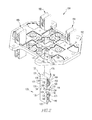
- FIG. 1 A typical electrical meter center 1 is illustrated in FIG. 1 .
- the meter center 1 includes a cabinet 3 having a plurality of meter socket assemblies 5 (only one is shown in FIG. 1 ) and a plurality of meters 11 .
- Each socket assembly 5 includes a base member 7 , to which various components of the socket assembly 5 are secured.
- Electrical power is supplied to the meter center 1 by a number of feeder buses 9 .
- the feeder buses 9 which typically consist of three phase buses and a neutral that are electrically connected to the utility lines (not shown), extend horizontally from the cabinet 3 , as shown in FIG. 1 .
- a pair of vertical supply buses (not shown) is electrically connected to the feeder buses 9 within the cabinet 3 .
- Each socket assembly 5 mounts a corresponding one of the meters 11 for each tenant circuit and electrically connects the meter 11 to the feeder buses 9 and the supply buses (not shown).
- the electrical connections between the meter 11 and the socket assembly 5 are made by plug-in jaws 17 of the socket assembly 5 , which engage corresponding stabs 19 of the meter 11 .
- the use of the plug-in jaws 17 within the socket assembly 5 , and corresponding stabs 19 on the back of the meter 11 permits the meter 11 to be removed from the socket assembly 5 when servicing the meter 11 is desired.
- a significant problem with known socket assemblies is that the plug-in jaws are often dislodged from the respective base members during use. More specifically, installation and/or removal of the meters often results in the jaws being pushed or pulled through the base members.
- a known approach to address this problem includes incorporating separate fasteners to secure the jaws to the base member. However, this approach is labor intensive and is difficult to automate.
- Another approach is to include small projections in the base member which extend into corresponding openings in the jaws in order to secure the jaws to the base members.
- a significant drawback of this approach is that the projections are often sheared off of the base member when the meters are installed and/or removed.
- a socket assembly for a meter center including at least one meter having a stab
- the socket assembly comprises a base member; and a jaw assembly comprising a first jaw member and a second jaw member coupled to the first jaw member, each of the first jaw member and the second jaw member having a number of retaining edges and being structured to engage the stab.
- the jaw assembly is structured to rotate between a first position corresponding to disengagement between the number of retaining edges and the base member, and a second position corresponding to engagement between the number of retaining edges and the base member.
- a meter center comprises a meter comprising a stab; and a socket assembly enclosed by the meter compartment, the socket assembly comprising a base member, and a jaw assembly comprising a first jaw member and a second jaw member coupled to the first jaw member, each of the first jaw member and the second jaw member having a number of retaining edges and being structured to engage the stab.
- the jaw assembly is structured to rotate between a first position corresponding to disengagement between the number of retaining edges and the base member, and a second position corresponding to engagement between the number of retaining edges and the base member.
- a method of assembling a socket assembly is provided.
- the socket assembly is for a meter center including at least one meter having a stab.
- the socket assembly has a base member and a jaw assembly.
- the jaw assembly includes a first jaw member and a second jaw member coupled to the first jaw member.
- Each of the first jaw member and the second jaw member have a number of retaining edges and are structured to engage the stab.
- the method comprises the steps of inserting the jaw assembly into a thru hole of the base member such that the number of retaining edges do not engage the base member; and rotating the jaw assembly with respect to the base member such that the number of retaining edges move into engagement with the base member, thereby preventing longitudinal movement of the first jaw member and the second jaw member with respect to the base member.
- FIG. 1 is a partially exploded front isometric view of a prior art meter center
- FIG. 2 is a partially exploded front isometric view of a socket assembly for a meter center, in accordance with a non-limiting embodiment of the disclosed concept;
- FIG. 3 is front isometric view of the socket assembly of FIG. 2 , shown with three jaw assemblies fully installed in a base member, and one jaw assembly partially installed in the base member;
- FIG. 4 is a front isometric view of the socket assembly of FIG. 3 , shown with one jaw assembly in a first position, before being rotated;
- FIG. 5 is a front isometric view of the socket assembly of FIG. 4 , shown with the same jaw assembly partially rotated;
- FIG. 6 is a front isometric view of the socket assembly of FIG. 5 , shown with the same jaw assembly fully rotated to a second, installed position.
- number shall mean one or an integer greater than one (i.e., a plurality).
- FIG. 2 shows a partially exploded view of a socket assembly 100 for a meter center, in accordance with a non-limiting embodiment of the disclosed concept.
- the example socket assembly 100 includes a base member 102 and a number of jaw assemblies 120 , 190 , 192 , 194 structured to be coupled to the base member 102 .
- the jaw assemblies 190 , 192 , 194 are substantially the same as the jaw assembly 120 , and are structured to be coupled to the base member 102 in substantially the same manner as the jaw assembly 120 .
- the jaw assembly 120 is structured to be coupled to the base member 102 by a twist-lock mechanism in order to prevent longitudinal and rotational movement of the jaw assembly 120 with respect to the base member 102 .
- this novel coupling mechanism advantageously ensures that during installation and/or removal of electrical apparatus (e.g., without limitation, electrical meters in meter centers (not shown)), the jaw assembly 120 is not pushed or pulled through the base member 102 .
- the coupling mechanism advantageously allows the socket assembly 100 to be manufactured using relatively simple automation processes.
- the jaw assembly 120 includes a pair of symmetric and identical jaw members 122 , 152 that are coupled to each other and are each structured to engage a conductive member (not shown), such as a stab of an electrical meter.
- a conductive member such as a stab of an electrical meter.
- the jaw members 122 , 152 each include a respective body portion 124 , 154 and a respective number of opposing tab portions 126 , 128 ( FIG. 5 ), 156 , 158 ( FIG. 5 ).
- the tab portions 126 , 128 , 156 , 158 are structured to prevent rotational movement of the jaw assembly 120 with respect to the base member, and the body portions 124 , 154 are structured to prevent longitudinal movement as well as assist in preventing rotational movement of the jaw assembly 120 with respect to the base member 102 , as will be discussed below.
- the body portions 124 , 154 each have a respective number of pairs of spaced apart and collinear external edges 129 , 130 , 131 , 132 , 159 , 160 , a respective number of retaining edges 133 , 134 , 135 , 136 , 165 , 166 extending inwardly from the external edges 129 , 130 , 131 , 132 , 159 , 160 toward each other, a pair of opposing side portions 137 , 138 , 167 ( FIG. 6 ), 168 ( FIG. 6 ), and a pair of opposing end portions 139 , 140 , 169 , 170 .
- the tab portions 126 , 128 , 156 , 158 extend from the respective retaining edges 133 , 134 , 135 , 136 , 165 , 166 toward each other and are each located between a corresponding pair of opposing retaining edges 133 , 134 , 135 , 136 , 165 , 166 .
- the jaw assembly 120 includes a pair of biasing elements (e.g., without limitation, springs 180 , 182 ) that bias the respective end portions 139 , 140 , 169 , 170 toward engagement with each other in order to allow a suitable electrical connection to be made with conductive stabs (not shown) of an electrical apparatus such as, for example, an electrical meter (not shown).
- the base member 102 includes a receiving portion 104 defining a thru hole for receiving the jaw assembly 120 , and a number of external blocking portions 108 , 110 .
- the receiving portion 104 also has a number of internal blocking portions 105 , 106 that are generally projections extending inwardly from a surface of the receiving portion 104 .
- FIG. 3 shows the socket assembly 100 with the jaw assembly 120 partially inserted into the receiving portion 104
- FIG. 4 shows the socket assembly 100 with the jaw assembly 120 fully inserted into the receiving portion 104
- the retaining edges 133 , 134 , 135 , 136 , 165 , 166 do not engage the base member 102
- the base member 102 is not located between any respective pair of opposing retaining edges 133 , 134 , 135 , 136 , 165 , 166 . That is, in the first position shown in FIG. 4 , the jaw assembly 120 is not maintained on (i.e., not prevented from easily being pushed or pulled through) the base member 102 , or not prevented from moving longitudinally with respect to the base member 102 .
- the jaw assembly 120 In order to couple the jaw assembly 120 to the base member 102 and thus provide a relatively secure structure for electrical apparatus (not shown) to engage, the jaw assembly 120 is structured to twist, or rotate (in the directions of arrows 201 , 202 in FIG. 6 ) with respect to the base member 102 and move from the first position ( FIG. 4 ) to a second position, shown in FIG. 6 .
- FIG. 5 shows the jaw assembly 120 in a third position that is between the first position ( FIG. 4 ) and the second position ( FIG. 6 ).
- the third position ( FIG. 5 ) corresponds to the jaw assembly 120 being partially rotated
- the second position ( FIG. 6 ) corresponds to the jaw assembly 120 being fully rotated to a secured position.
- the jaw assembly 120 rotates approximately ninety degrees with respect to the base member 102 when moving from the first position ( FIG. 4 ) to the second position ( FIG. 6 ).
- any suitable alternative angle of rotation may be employed in order to perform the desired coupling function, without departing from the scope of the disclosed concept.
- the retaining edges 133 , 134 , 135 , 136 , 165 , 166 move into engagement with and overlay the base member 102 in order to prevent longitudinal movement of the jaw members 122 , 152 with respect to the base member 102 . More specifically, when the jaw assembly 120 is in the third position ( FIG. 5 ) and the second position ( FIG. 6 ), the base member 102 is located between each corresponding opposing pair of the retaining edges 133 , 134 , 135 , 136 , 165 , 166 .
- the retaining edges 133 , 134 , 135 , 136 , 165 , 166 advantageously provide a relatively secure mechanism to longitudinally secure the jaw assembly 120 to the base member 102 . That is, there are four locations that ensure that the jaw assembly 120 is not able to be inadvertently pulled through the base member 102 .
- a similar suitable alternative jaw assembly may have any suitable alternative number of retaining edges and/or construction of jaw members (e.g., not being identical) in order to perform the desired function of preventing longitudinal movement though the base member 102 .
- the socket assembly 100 also has a mechanism to prevent rotational movement of the jaw assembly 120 with respect to the base member 102 when the jaw assembly 120 is in the second, installed position ( FIG. 6 ). More specifically, when the jaw assembly 120 is in the first position ( FIG. 4 ) and the third position ( FIG. 5 ), the blocking portion 105 is not located between the tab portions 128 , 158 , and the blocking portion 106 is not located between the tab portions 126 , 156 ( FIG. 2 ). As shown in FIG. 6 , when the jaw assembly 120 is in the second position, the blocking portion 105 is located between the tab portions 128 , 158 (i.e., directly between and separating distal ends of the respective tab portions 128 , 158 ). It will similarly be appreciated that in the second position ( FIG. 6 ), the blocking portion 106 is located between the tab portions 126 , 156 ( FIG. 2 ).
- the tab portions 126 ( FIG. 2 ), 158 When the jaw assembly 120 moves from the first position to the second position, the tab portions 126 ( FIG. 2 ), 158 initially flex (i.e., deflect) inwardly toward each other as they are twisted over the respective blocking portions 105 , 106 . However, at the instant the jaw assembly 120 is twisted to the second position, the tab portions 126 ( FIG. 2 ), 158 flex outwardly away from each other and return to the position in which they are not deflected in order to allow the respective blocking portions 105 , 106 to be located between the respective tab portions 126 ( FIG. 2 ), 128 , 156 ( FIG. 2 ), 158 and resist rotation of the jaw assembly 120 with respect to the base member 102 .
- the external blocking portions 108 , 110 further assist in preventing undesired rotation of the jaw assembly 120 with respect to the base member 102 . More specifically, when the jaw assembly 120 is in the first position ( FIG. 4 ), the first side portions 137 , 167 engage the respective blocking portions 108 , 110 and the second side portions 138 , 168 do not engage the respective blocking portions 110 . When the jaw assembly 120 moves toward the second position ( FIG. 4 ), the first side portions 137 , 167 engage the respective blocking portions 108 , 110 and the second side portions 138 , 168 do not engage the respective blocking portions 110 . When the jaw assembly 120 moves toward the second position ( FIG.
- the first side portions 137 , 167 disengage the respective blocking portions 108 , 110 and the second side portions 138 , 168 move, or rotate, toward the respective blocking portions 108 , 110 until the second side portions 138 , 168 actually move into engagement with the respective blocking portions 108 , 110 (see FIG. 6 ).
- an attempted rotation of the jaw assembly 120 in the second direction 202 would result in the second side portions 138 , 168 pressing into the respective blocking portions 108 , 110 .
- the normal force exerted by the blocking portions 108 , 110 on the respective second side portions 138 , 168 advantageously operates to further prevent undesired rotation of the jaw assembly 120 with respect to the base member 102 .
- suitable alternative mechanisms may be employed to prevent undesired rotation without departing from the scope of the disclosed concept.
- the retaining edges 133 , 134 , 135 , 136 , 165 , 166 and the tab portions 126 , 128 , 156 , 158 thus advantageously cooperatively secure the jaw members 122 , 152 to the base member 102 without a separate fastener when the jaw assembly 120 is in the second position ( FIG. 6 ).
- automation of the socket assembly 100 is relatively simple in that an insertion and rotation of the jaw assemblies 120 , 190 , 192 , 194 into and with respect to the base member 102 is all that is required to reliably couple the jaw assemblies 120 , 190 , 192 , 194 to the base member 102 .
- This is distinct from some known socket assemblies (not shown) which require more burdensome methods of assembly such as, for example, drilling holes and manually inserting separate fasteners to secure jaw assemblies to base members.
- a method of assembling the socket assembly 100 includes the steps of inserting the jaw assembly 120 into the thru hole of the base member 102 such that the retaining edges 133 , 134 , 135 , 136 , 165 , 166 do not engage the base member 102 ; and rotating the jaw assembly 120 with respect to the base member 102 such that the retaining edges 133 , 134 , 135 , 136 , 165 , 166 move into engagement with the base member 102 , thereby preventing longitudinal movement of the first jaw member 122 and the second jaw member 152 with respect to the base member 102 .
- the rotating step further includes the steps of moving the first side portions 137 , 167 out of engagement with the respective blocking portions 108 , 110 ; and moving the second side portions 138 , 168 into engagement with the respective blocking portions 108 , 110 in order to prevent rotation of the jaw members 122 , 152 in a direction 202 with respect to the base member 102 .
- the rotating step also includes rotating the jaw assembly 120 ninety degrees with respect to the base member 102 until the second side portions 138 , 168 move into engagement with the respective blocking portions 108 , 110 .
- the rotating step further includes rotating the jaw assembly 120 until the internal blocking portions 105 , 106 are located between the respective tab portions 126 , 128 , 156 , 158 , thereby preventing rotational movement of the jaw members 122 , 152 with respect to the base member 102 .
- the disclosed concept provides for an improved (e.g., without limitation, better maintained, easier to automate) meter center, and socket assembly 100 and method of assembling a socket assembly 100 therefor, in which a number of jaw assemblies 120 , 190 , 192 , 194 are structured to rotate with respect to a base member 102 in order to quickly and reliably secure the jaw assemblies 120 , 190 , 192 , 194 to the base member 102 in such a way that undesirable longitudinal and rotational movement of the jaw assemblies 120 , 190 , 192 , 194 with respect to the base member 102 is advantageously prevented.
- a number of jaw assemblies 120 , 190 , 192 , 194 are structured to rotate with respect to a base member 102 in order to quickly and reliably secure the jaw assemblies 120 , 190 , 192 , 194 to the base member 102 in such a way that undesirable longitudinal and rotational movement of the jaw assemblies 120 , 190 , 192 , 194 with respect to the base member 102 is advantageous
Landscapes
- Engineering & Computer Science (AREA)
- Manufacturing & Machinery (AREA)
- Physics & Mathematics (AREA)
- General Physics & Mathematics (AREA)
- Connector Housings Or Holding Contact Members (AREA)
Priority Applications (3)
| Application Number | Priority Date | Filing Date | Title |
|---|---|---|---|
| US14/944,734 US9537245B1 (en) | 2015-11-18 | 2015-11-18 | Meter center, and socket assembly and method of assembling a socket assembly therefor |
| CA2940741A CA2940741C (fr) | 2015-11-18 | 2016-08-31 | Appareil de mesure de centre et dispositif de douille et methode d'assemblage d'un dispositif de douille associe |
| US15/358,303 US9768540B2 (en) | 2015-11-18 | 2016-11-22 | Meter center, and socket assembly and method of assembling a socket assembly therefor |
Applications Claiming Priority (1)
| Application Number | Priority Date | Filing Date | Title |
|---|---|---|---|
| US14/944,734 US9537245B1 (en) | 2015-11-18 | 2015-11-18 | Meter center, and socket assembly and method of assembling a socket assembly therefor |
Related Child Applications (1)
| Application Number | Title | Priority Date | Filing Date |
|---|---|---|---|
| US15/358,303 Continuation US9768540B2 (en) | 2015-11-18 | 2016-11-22 | Meter center, and socket assembly and method of assembling a socket assembly therefor |
Publications (1)
| Publication Number | Publication Date |
|---|---|
| US9537245B1 true US9537245B1 (en) | 2017-01-03 |
Family
ID=57682442
Family Applications (2)
| Application Number | Title | Priority Date | Filing Date |
|---|---|---|---|
| US14/944,734 Active US9537245B1 (en) | 2015-11-18 | 2015-11-18 | Meter center, and socket assembly and method of assembling a socket assembly therefor |
| US15/358,303 Active US9768540B2 (en) | 2015-11-18 | 2016-11-22 | Meter center, and socket assembly and method of assembling a socket assembly therefor |
Family Applications After (1)
| Application Number | Title | Priority Date | Filing Date |
|---|---|---|---|
| US15/358,303 Active US9768540B2 (en) | 2015-11-18 | 2016-11-22 | Meter center, and socket assembly and method of assembling a socket assembly therefor |
Country Status (2)
| Country | Link |
|---|---|
| US (2) | US9537245B1 (fr) |
| CA (1) | CA2940741C (fr) |
Cited By (2)
| Publication number | Priority date | Publication date | Assignee | Title |
|---|---|---|---|---|
| US9768540B2 (en) * | 2015-11-18 | 2017-09-19 | Eaton Corporation | Meter center, and socket assembly and method of assembling a socket assembly therefor |
| US10256560B2 (en) * | 2016-10-28 | 2019-04-09 | Te Connectivity Germany Gmbh | Flat contact socket with a cantilever |
Families Citing this family (1)
| Publication number | Priority date | Publication date | Assignee | Title |
|---|---|---|---|---|
| US12279695B2 (en) | 2021-12-22 | 2025-04-22 | Abb Schweiz Ag | Self aligning wall rail for enclosure wall mounting |
Citations (13)
| Publication number | Priority date | Publication date | Assignee | Title |
|---|---|---|---|---|
| US4201439A (en) * | 1978-12-18 | 1980-05-06 | General Electric Company | Meter jaw and spring clip assembly |
| US5951324A (en) | 1997-12-09 | 1999-09-14 | Eaton Corporation | Socket assembly for meter center |
| US5982611A (en) | 1997-12-09 | 1999-11-09 | Eaton Corporation | Meter center with fastenerless current carrying connections |
| US5980311A (en) | 1997-12-09 | 1999-11-09 | Eaton Corporation | Fastenerless double ended clip-on meter jaw |
| US6012937A (en) | 1997-12-09 | 2000-01-11 | Eaton Corporation | Supply bus bars for meter center |
| US6015314A (en) | 1997-11-07 | 2000-01-18 | Colsolidated Edison Company Of New York, Inc. | Electric watt-hour meter adapter |
| US20020182930A1 (en) * | 2001-05-31 | 2002-12-05 | Eaton Corporation | Clamping mechanism for horn bypass jumper cable assembly |
| US6561844B1 (en) | 2001-11-13 | 2003-05-13 | Eaton Corporation | Lug for providing both electrical and mechanical connection between buses and watt hour meter sockets |
| US6561304B1 (en) * | 2000-10-02 | 2003-05-13 | Delphi Technologies, Inc. | Rotary actuator assembly |
| US6793542B1 (en) | 2003-07-17 | 2004-09-21 | Eaton Corporation | Clamp-jaw contact assembly and meter socket employing the same |
| US20050202715A1 (en) * | 2004-03-09 | 2005-09-15 | Cooper Technologies Company | Socket assembly for an electric meter box |
| US7239502B1 (en) | 2006-01-20 | 2007-07-03 | Eaton Corporation | Meter center and multi-phase multiple meter socket assembly therefor |
| US7522406B2 (en) | 2007-07-31 | 2009-04-21 | Eaton Corporation | Meter center, and socket assembly and jaw assembly therefor |
Family Cites Families (1)
| Publication number | Priority date | Publication date | Assignee | Title |
|---|---|---|---|---|
| US9537245B1 (en) * | 2015-11-18 | 2017-01-03 | Eaton Corporation | Meter center, and socket assembly and method of assembling a socket assembly therefor |
-
2015
- 2015-11-18 US US14/944,734 patent/US9537245B1/en active Active
-
2016
- 2016-08-31 CA CA2940741A patent/CA2940741C/fr active Active
- 2016-11-22 US US15/358,303 patent/US9768540B2/en active Active
Patent Citations (15)
| Publication number | Priority date | Publication date | Assignee | Title |
|---|---|---|---|---|
| US4201439A (en) * | 1978-12-18 | 1980-05-06 | General Electric Company | Meter jaw and spring clip assembly |
| US6015314A (en) | 1997-11-07 | 2000-01-18 | Colsolidated Edison Company Of New York, Inc. | Electric watt-hour meter adapter |
| US5951324A (en) | 1997-12-09 | 1999-09-14 | Eaton Corporation | Socket assembly for meter center |
| US5982611A (en) | 1997-12-09 | 1999-11-09 | Eaton Corporation | Meter center with fastenerless current carrying connections |
| US5980311A (en) | 1997-12-09 | 1999-11-09 | Eaton Corporation | Fastenerless double ended clip-on meter jaw |
| US6012937A (en) | 1997-12-09 | 2000-01-11 | Eaton Corporation | Supply bus bars for meter center |
| US6561304B1 (en) * | 2000-10-02 | 2003-05-13 | Delphi Technologies, Inc. | Rotary actuator assembly |
| US20020182930A1 (en) * | 2001-05-31 | 2002-12-05 | Eaton Corporation | Clamping mechanism for horn bypass jumper cable assembly |
| US6561844B1 (en) | 2001-11-13 | 2003-05-13 | Eaton Corporation | Lug for providing both electrical and mechanical connection between buses and watt hour meter sockets |
| US20030092312A1 (en) | 2001-11-13 | 2003-05-15 | Eaton Corporation | Lug for providing both electrical and mechanical connection between buses and watt hour meter sockets |
| US6793542B1 (en) | 2003-07-17 | 2004-09-21 | Eaton Corporation | Clamp-jaw contact assembly and meter socket employing the same |
| US20050202715A1 (en) * | 2004-03-09 | 2005-09-15 | Cooper Technologies Company | Socket assembly for an electric meter box |
| US6945813B1 (en) * | 2004-03-09 | 2005-09-20 | Cooper Technologies Company | Socket assembly for electric meter box |
| US7239502B1 (en) | 2006-01-20 | 2007-07-03 | Eaton Corporation | Meter center and multi-phase multiple meter socket assembly therefor |
| US7522406B2 (en) | 2007-07-31 | 2009-04-21 | Eaton Corporation | Meter center, and socket assembly and jaw assembly therefor |
Cited By (2)
| Publication number | Priority date | Publication date | Assignee | Title |
|---|---|---|---|---|
| US9768540B2 (en) * | 2015-11-18 | 2017-09-19 | Eaton Corporation | Meter center, and socket assembly and method of assembling a socket assembly therefor |
| US10256560B2 (en) * | 2016-10-28 | 2019-04-09 | Te Connectivity Germany Gmbh | Flat contact socket with a cantilever |
Also Published As
| Publication number | Publication date |
|---|---|
| US9768540B2 (en) | 2017-09-19 |
| CA2940741A1 (fr) | 2017-05-18 |
| CA2940741C (fr) | 2023-07-25 |
| US20170141504A1 (en) | 2017-05-18 |
Similar Documents
| Publication | Publication Date | Title |
|---|---|---|
| US10541519B1 (en) | Large current circuit breaker plug-in installation | |
| US3885852A (en) | Quick couple electric outlet | |
| US20080251650A1 (en) | Double mounted dual switch box bracket - stud divider | |
| US8295060B2 (en) | Mounting apparatus and system for PCI card | |
| US9768540B2 (en) | Meter center, and socket assembly and method of assembling a socket assembly therefor | |
| US10148046B2 (en) | Holding frame for plug connector modules | |
| CN104064411B (zh) | 一种断路器的接线装置、断路器以及断路器组件 | |
| US9184525B1 (en) | Power distribution system and contact retention assembly therefor | |
| US20230144867A1 (en) | Improved cabling device for electrical distribution devices | |
| US7522406B2 (en) | Meter center, and socket assembly and jaw assembly therefor | |
| US20100130042A1 (en) | Connector socket, a connector plug, and an appliance fitted with a connector | |
| US10680395B2 (en) | Universal power interface system and methods to use the same | |
| BR112017027444B1 (pt) | Peça de conector elétrico e dispositivo conector | |
| US20150124377A1 (en) | Flexible electrical power connection | |
| RU2650328C2 (ru) | Блок охлаждения, содержащий средства компенсации производственных допусков | |
| CN106654761A (zh) | 插头 | |
| CN104378935A (zh) | 一种出线腔盖板锁紧装置 | |
| CN109314361B (zh) | 插头连接器的组装方法 | |
| JP2021506211A (ja) | 柱間コネクタにより相互接続された2つのスイッチキャビネットラックから構成される配置構造 | |
| EP2797096B1 (fr) | Disjoncteur et son dispositif de verrouillage de poignée | |
| KR20150001577U (ko) | 접지용 단자 | |
| CN107425307A (zh) | 万向接地线 | |
| EP2906887B1 (fr) | Appareil frigorifique comprenant une électrovanne | |
| US10844979B2 (en) | Sectional guide pole for wiring | |
| CN217545287U (zh) | 一种开关柜 |
Legal Events
| Date | Code | Title | Description |
|---|---|---|---|
| AS | Assignment |
Owner name: EATON CORPORATION, OHIO Free format text: ASSIGNMENT OF ASSIGNORS INTEREST;ASSIGNOR:CABLE, ALBERT BOYD;REEL/FRAME:037145/0699 Effective date: 20151118 |
|
| STCF | Information on status: patent grant |
Free format text: PATENTED CASE |
|
| AS | Assignment |
Owner name: EATON INTELLIGENT POWER LIMITED, IRELAND Free format text: ASSIGNMENT OF ASSIGNORS INTEREST;ASSIGNOR:EATON CORPORATION;REEL/FRAME:048855/0626 Effective date: 20171231 |
|
| MAFP | Maintenance fee payment |
Free format text: PAYMENT OF MAINTENANCE FEE, 4TH YEAR, LARGE ENTITY (ORIGINAL EVENT CODE: M1551); ENTITY STATUS OF PATENT OWNER: LARGE ENTITY Year of fee payment: 4 |
|
| MAFP | Maintenance fee payment |
Free format text: PAYMENT OF MAINTENANCE FEE, 8TH YEAR, LARGE ENTITY (ORIGINAL EVENT CODE: M1552); ENTITY STATUS OF PATENT OWNER: LARGE ENTITY Year of fee payment: 8 |