US955801A - Form for laying concrete curbs and gutters. - Google Patents
Form for laying concrete curbs and gutters. Download PDFInfo
- Publication number
- US955801A US955801A US49011409A US1909490114A US955801A US 955801 A US955801 A US 955801A US 49011409 A US49011409 A US 49011409A US 1909490114 A US1909490114 A US 1909490114A US 955801 A US955801 A US 955801A
- Authority
- US
- United States
- Prior art keywords
- bars
- gutter
- plates
- curb
- gutters
- Prior art date
- Legal status (The legal status is an assumption and is not a legal conclusion. Google has not performed a legal analysis and makes no representation as to the accuracy of the status listed.)
- Expired - Lifetime
Links
- 239000002184 metal Substances 0.000 description 5
- 210000002105 tongue Anatomy 0.000 description 3
- 239000002023 wood Substances 0.000 description 3
- 238000010276 construction Methods 0.000 description 2
- 239000002131 composite material Substances 0.000 description 1
- 230000008602 contraction Effects 0.000 description 1
- 230000004048 modification Effects 0.000 description 1
- 238000012986 modification Methods 0.000 description 1
- 230000000284 resting effect Effects 0.000 description 1
Images
Classifications
-
- E—FIXED CONSTRUCTIONS
- E01—CONSTRUCTION OF ROADS, RAILWAYS, OR BRIDGES
- E01C—CONSTRUCTION OF, OR SURFACES FOR, ROADS, SPORTS GROUNDS, OR THE LIKE; MACHINES OR AUXILIARY TOOLS FOR CONSTRUCTION OR REPAIR
- E01C19/00—Machines, tools or auxiliary devices for preparing or distributing paving materials, for working the placed materials, or for forming, consolidating, or finishing the paving
- E01C19/50—Removable forms or shutterings for road-building purposes; Devices or arrangements for forming individual paving elements, e.g. kerbs, in situ
- E01C19/502—Removable forms or shutterings, e.g. side forms; Removable supporting or anchoring means therefor, e.g. stakes
- E01C19/506—Removable forms or shutterings, e.g. side forms; Removable supporting or anchoring means therefor, e.g. stakes for kerbs, gutters or similar structures, e.g. raised portions, median barriers
Definitions
- This invention relates to an improvement in the construction of the forms employed in laying composite concrete curbs and gutters; my object being to provide a form with division plates, whereby expansion joints of proper width will be made at proper intervals, throughout the line of curbing, said joints extending completely through the curb and gutter so as to divide the concrete into blocks of suitable length; and to so construct the division plates that they will be susceptible of adjustment to any height of the curbing above the gutter, and serve also as guides for surfacing the gutter and curb.
- back bars 1 for the curb form which may be of wood or metal, the top edge of said bars being set on the line of the top of the curb and the depth of the bars corresponding to the height of the curb plus the thickness of the gutter.
- the street side of the form, or front gutter bars 2 I preferably construct of sheet metal strips flanged along the top and bottom edges, said strips corresponding in depth to the thickness of the gutter, and being made in interlocking sections in the same manner as the side bars described in my co-pending application for forms for layin concrete walks, filed March 31, 1909, Serial No. 486,884. In fact, the side bars for said walk forms may be used in connection with my curb forms without change.
- These front bars 2 are spaced from the back bars 1 by means of metal angle plates 3,
- the upright members 4 of these division plates being set up against the back bars 1, and being provided at 5 with vertical slots to receive bolts by which supporting arms 6 are fas tened in place, said arms where they project to the rear resting upon the top of the bars 1, to hold the division plates at the proper height.
- these division plates in my preferred construction, are provided with tongues 7, which project through corresponding slots in the front bars 2, said bars being fastened to the plates by means of wedges 8 driven into slots in the tongues 7.
- the bars 2 are fastened together, where their ends abut, by means of a tongue 9 projecting from one bar and inserted in a slot in an outturned flange 10 at the end of the next bar, as described in my said co-pending application.
- WVhen thus set up, with the division plates at suitable, intervals, the form is completed by set ting up the outside curb bars 11, (see Fig. 2), against the vertical portions 4 of the division plates, and clamping the bars 1 and 11 against the opposite edges of said upward extensions 4, by means of any suitable form of clamp, as indicated by the broken lines at 18 in Fig. 2.
- the members of the form are thus all securely fastened together, and independent of stakes or other holding devices for maintaining them in place while the concrete is filled in and surfaced otl.
- the concrete When so set up, the concrete will be filled into the form and the upper surface of the gutter will be struck off by means of a straight edge passed over the top edges of the division plates 3, said top edges lying ilush with the top edge of the front bars 2, so that the gutter blocks will be left with .pansion and contraction.
- the curb will be formed by filling in the concrete between the bars 1 and 11, and striking off the top surface by a straight edge passed along the top edges of the bars. After the concrete has been. filled in and surfaced in this manner, the front bars 2 will be removed from the division plates,
Landscapes
- Engineering & Computer Science (AREA)
- Architecture (AREA)
- Civil Engineering (AREA)
- Structural Engineering (AREA)
- Road Paving Structures (AREA)
Description
M. S. HOTGHKISS. FORM FOR LAYING GONGRETE GURBS AND GUTTBRS.
APPLIOATIONIILED mi. 15, 1909.
Patented Apr. 19,1910.
r J1) '1 w L L WITNESSES: 5. Z/MM ATTORNEY UNITED STATES PATENT OFFIGE.
MARK S. HOTCHKISS, OF LESTERSHIRE, NEW YORK, ASSIGNOR TO HOTCHKISS LOCK METAL FORM COMPANY, OF BINGHAMTON, NEW YORK.
FORM FOR LAYING CONCRETE CURBS AND GU'ITERS.
Specification of Letters Patent.
Patented Apr. 19, 19110.
Application filed April 15, 1909. Serial No. 490,114.
To all whom it may concern:
Be it known that I, MARK S. Ho'rornnss, a citizen of the United States, residing at Lestershire in the county of Broome and State of New York, have invented certain new and useful Improvements in Forms for Laying Concrete Curbs and Gutters, of which the following is a specification.
This invention relates to an improvement in the construction of the forms employed in laying composite concrete curbs and gutters; my object being to provide a form with division plates, whereby expansion joints of proper width will be made at proper intervals, throughout the line of curbing, said joints extending completely through the curb and gutter so as to divide the concrete into blocks of suitable length; and to so construct the division plates that they will be susceptible of adjustment to any height of the curbing above the gutter, and serve also as guides for surfacing the gutter and curb.
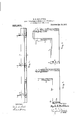
I attain my object by constructing the curb and gutter forms and expansion joint plates in the manner illustrated in the accompanying drawings, in which- Figure 1 represents a side elevation of a curb and gutter form set up to embody my improvements; Fig. 2, a cross section thereof upon an enlarged scale; and Fig. 3, a corresponding sectional view in a slightly modified form.
Like numerals designate like parts in the several views.
In setting up my form I employ back bars 1 for the curb form, which may be of wood or metal, the top edge of said bars being set on the line of the top of the curb and the depth of the bars corresponding to the height of the curb plus the thickness of the gutter. The street side of the form, or front gutter bars 2, I preferably construct of sheet metal strips flanged along the top and bottom edges, said strips corresponding in depth to the thickness of the gutter, and being made in interlocking sections in the same manner as the side bars described in my co-pending application for forms for layin concrete walks, filed March 31, 1909, Serial No. 486,884. In fact, the side bars for said walk forms may be used in connection with my curb forms without change. These front bars 2 are spaced from the back bars 1 by means of metal angle plates 3,
which are cut to conform to the thickness of the gutter and curb blocks, the upright members 4 of these division plates being set up against the back bars 1, and being provided at 5 with vertical slots to receive bolts by which supporting arms 6 are fas tened in place, said arms where they project to the rear resting upon the top of the bars 1, to hold the division plates at the proper height. At their outward ends these division plates, in my preferred construction, are provided with tongues 7, which project through corresponding slots in the front bars 2, said bars being fastened to the plates by means of wedges 8 driven into slots in the tongues 7. The bars 2 are fastened together, where their ends abut, by means of a tongue 9 projecting from one bar and inserted in a slot in an outturned flange 10 at the end of the next bar, as described in my said co-pending application. WVhen thus set up, with the division plates at suitable, intervals, the form is completed by set ting up the outside curb bars 11, (see Fig. 2), against the vertical portions 4 of the division plates, and clamping the bars 1 and 11 against the opposite edges of said upward extensions 4, by means of any suitable form of clamp, as indicated by the broken lines at 18 in Fig. 2. The members of the form are thus all securely fastened together, and independent of stakes or other holding devices for maintaining them in place while the concrete is filled in and surfaced otl.
As the curb, on level streets, must have its upward edge on the level, while the gutter must be slant-ed more or less to the catch basins, the back bars 1 will be level, while the front gutter bars 2 must be set at the angle of inclination toward the catch basins. The upper edges of the back bars and the front bars will, therefore, recede from one another, and the division plates must be dropped to correspond, this drop being allowed for by the adjustment of the arms 6 on the several plates. This difference in adjustment is shown at Figs. 1 and 2. When so set up, the concrete will be filled into the form and the upper surface of the gutter will be struck off by means of a straight edge passed over the top edges of the division plates 3, said top edges lying ilush with the top edge of the front bars 2, so that the gutter blocks will be left with .pansion and contraction.
true and perfect outward edges, when the straight edge is passed over the division plates and out across the top of the front bars. The curb will be formed by filling in the concrete between the bars 1 and 11, and striking off the top surface by a straight edge passed along the top edges of the bars. After the concrete has been. filled in and surfaced in this manner, the front bars 2 will be removed from the division plates,
and also the form bars 1 and 11, after which the division plates will be drawn out, thereby leaving the concrete blocks with spaces between of a suitable width to allow for eX- For this purpose I propose to make the division plates 3 of metal plates one-eighth of an inch in thickness. here wood forms are to be used in connection with these division plates, as shown in Fig. 3, (2 in said figure representinga front bar of wood), I provide the division plates 3*" with upwardly and outwardly projecting arms 12, adapted to rest upon the upper edge of the bars 2*. In other respects the forms will be the same as already described. In this modification the gutter cannot be so well surfaced as in my preferred form; inasmuch as the arms 12 interfere with the movement of the straight edge over the division plates in striking the surface. The surface between plates on the outward edge of the gutter must in this case be finished after the division plates are removed; or while they are in place by working up to the arms 12 along the upper edge of the bars 2 Moreover, stakes are required to hold these front bars in place.
hat I claim as my invention and desire to secure by Letters Patent is In a form of the character described, the combination with front and back bars, of an angled division plate having a horizontal member provided with means for engaging the front bar and a vertical member eXtending above the back bar and provided witha vertical slot adjacent its rear end, an arm movably mounted on said member and adapted to rest upon the top of the back bar,
and means passing through said slot above MARK .S. HOTCHKISS.
Witnesses:
W. D. EDMISTER, CAssm A. Ron.
Priority Applications (1)
| Application Number | Priority Date | Filing Date | Title |
|---|---|---|---|
| US49011409A US955801A (en) | 1909-04-15 | 1909-04-15 | Form for laying concrete curbs and gutters. |
Applications Claiming Priority (1)
| Application Number | Priority Date | Filing Date | Title |
|---|---|---|---|
| US49011409A US955801A (en) | 1909-04-15 | 1909-04-15 | Form for laying concrete curbs and gutters. |
Publications (1)
| Publication Number | Publication Date |
|---|---|
| US955801A true US955801A (en) | 1910-04-19 |
Family
ID=3024205
Family Applications (1)
| Application Number | Title | Priority Date | Filing Date |
|---|---|---|---|
| US49011409A Expired - Lifetime US955801A (en) | 1909-04-15 | 1909-04-15 | Form for laying concrete curbs and gutters. |
Country Status (1)
| Country | Link |
|---|---|
| US (1) | US955801A (en) |
Cited By (1)
| Publication number | Priority date | Publication date | Assignee | Title |
|---|---|---|---|---|
| US20050126098A1 (en) * | 2003-12-15 | 2005-06-16 | Walters Russell D. | Panel system for forming poured concrete walls |
-
1909
- 1909-04-15 US US49011409A patent/US955801A/en not_active Expired - Lifetime
Cited By (1)
| Publication number | Priority date | Publication date | Assignee | Title |
|---|---|---|---|---|
| US20050126098A1 (en) * | 2003-12-15 | 2005-06-16 | Walters Russell D. | Panel system for forming poured concrete walls |
Similar Documents
| Publication | Publication Date | Title |
|---|---|---|
| US4815886A (en) | Expansion joint for concrete and method for use | |
| US1379440A (en) | Paving-block | |
| US955801A (en) | Form for laying concrete curbs and gutters. | |
| US1682008A (en) | Concrete form | |
| US985035A (en) | Form for the construction of concrete walks, floors, curbs, gutters, and like structures. | |
| US584269A (en) | Combination paving-block and system of paving | |
| US940061A (en) | Apparatus for laying concrete sidewalks, curbs, &c. | |
| US149658A (en) | Improvement in artificial-stone pavements | |
| US729852A (en) | Mechanism for making sidewalks, curbs, and gutters. | |
| US442060A (en) | Curbing and gutter | |
| US1358042A (en) | Roadway reinforcement | |
| US1067501A (en) | Street-curbing. | |
| US3292508A (en) | Wedge device | |
| US1944257A (en) | Adjustable curb face | |
| US1170452A (en) | Templet for concrete gutters. | |
| US1768838A (en) | Collapsible form | |
| US140835A (en) | Improvement in pavements | |
| US1178700A (en) | Pavement-joint. | |
| US1207738A (en) | Paving construction. | |
| US872602A (en) | Form for concrete sidewalks. | |
| US1289688A (en) | Expansion-joint and support therefor. | |
| US688851A (en) | Metallic curb. | |
| US1092848A (en) | Joint-plate. | |
| US1214870A (en) | Mold for making concrete curbs. | |
| AU665662B2 (en) | Element for forming controlled cracks in concrete slabs |