US9558080B2 - Crash recovery using non-volatile memory - Google Patents
Crash recovery using non-volatile memory Download PDFInfo
- Publication number
- US9558080B2 US9558080B2 US14/069,028 US201314069028A US9558080B2 US 9558080 B2 US9558080 B2 US 9558080B2 US 201314069028 A US201314069028 A US 201314069028A US 9558080 B2 US9558080 B2 US 9558080B2
- Authority
- US
- United States
- Prior art keywords
- volatile memory
- pages
- page
- memory
- intermediate non
- Prior art date
- Legal status (The legal status is an assumption and is not a legal conclusion. Google has not performed a legal analysis and makes no representation as to the accuracy of the status listed.)
- Active, expires
Links
Images



Classifications
-
- G—PHYSICS
- G06—COMPUTING OR CALCULATING; COUNTING
- G06F—ELECTRIC DIGITAL DATA PROCESSING
- G06F11/00—Error detection; Error correction; Monitoring
- G06F11/07—Responding to the occurrence of a fault, e.g. fault tolerance
- G06F11/0703—Error or fault processing not based on redundancy, i.e. by taking additional measures to deal with the error or fault not making use of redundancy in operation, in hardware, or in data representation
- G06F11/0793—Remedial or corrective actions
-
- G—PHYSICS
- G06—COMPUTING OR CALCULATING; COUNTING
- G06F—ELECTRIC DIGITAL DATA PROCESSING
- G06F11/00—Error detection; Error correction; Monitoring
- G06F11/07—Responding to the occurrence of a fault, e.g. fault tolerance
- G06F11/14—Error detection or correction of the data by redundancy in operations
- G06F11/1402—Saving, restoring, recovering or retrying
- G06F11/1415—Saving, restoring, recovering or retrying at system level
- G06F11/1441—Resetting or repowering
-
- G—PHYSICS
- G06—COMPUTING OR CALCULATING; COUNTING
- G06F—ELECTRIC DIGITAL DATA PROCESSING
- G06F11/00—Error detection; Error correction; Monitoring
- G06F11/07—Responding to the occurrence of a fault, e.g. fault tolerance
- G06F11/0703—Error or fault processing not based on redundancy, i.e. by taking additional measures to deal with the error or fault not making use of redundancy in operation, in hardware, or in data representation
- G06F11/0706—Error or fault processing not based on redundancy, i.e. by taking additional measures to deal with the error or fault not making use of redundancy in operation, in hardware, or in data representation the processing taking place on a specific hardware platform or in a specific software environment
- G06F11/0727—Error or fault processing not based on redundancy, i.e. by taking additional measures to deal with the error or fault not making use of redundancy in operation, in hardware, or in data representation the processing taking place on a specific hardware platform or in a specific software environment in a storage system, e.g. in a DASD or network based storage system
-
- G—PHYSICS
- G06—COMPUTING OR CALCULATING; COUNTING
- G06F—ELECTRIC DIGITAL DATA PROCESSING
- G06F11/00—Error detection; Error correction; Monitoring
- G06F11/07—Responding to the occurrence of a fault, e.g. fault tolerance
- G06F11/0703—Error or fault processing not based on redundancy, i.e. by taking additional measures to deal with the error or fault not making use of redundancy in operation, in hardware, or in data representation
- G06F11/0751—Error or fault detection not based on redundancy
-
- G—PHYSICS
- G06—COMPUTING OR CALCULATING; COUNTING
- G06F—ELECTRIC DIGITAL DATA PROCESSING
- G06F11/00—Error detection; Error correction; Monitoring
- G06F11/07—Responding to the occurrence of a fault, e.g. fault tolerance
- G06F11/0703—Error or fault processing not based on redundancy, i.e. by taking additional measures to deal with the error or fault not making use of redundancy in operation, in hardware, or in data representation
- G06F11/079—Root cause analysis, i.e. error or fault diagnosis
-
- G—PHYSICS
- G06—COMPUTING OR CALCULATING; COUNTING
- G06F—ELECTRIC DIGITAL DATA PROCESSING
- G06F11/00—Error detection; Error correction; Monitoring
- G06F11/07—Responding to the occurrence of a fault, e.g. fault tolerance
- G06F11/14—Error detection or correction of the data by redundancy in operations
- G06F11/1446—Point-in-time backing up or restoration of persistent data
- G06F11/1458—Management of the backup or restore process
- G06F11/1469—Backup restoration techniques
-
- G—PHYSICS
- G06—COMPUTING OR CALCULATING; COUNTING
- G06F—ELECTRIC DIGITAL DATA PROCESSING
- G06F11/00—Error detection; Error correction; Monitoring
- G06F11/07—Responding to the occurrence of a fault, e.g. fault tolerance
- G06F11/14—Error detection or correction of the data by redundancy in operations
- G06F11/1471—Error detection or correction of the data by redundancy in operations involving logging of persistent data for recovery
-
- G—PHYSICS
- G06—COMPUTING OR CALCULATING; COUNTING
- G06F—ELECTRIC DIGITAL DATA PROCESSING
- G06F11/00—Error detection; Error correction; Monitoring
- G06F11/07—Responding to the occurrence of a fault, e.g. fault tolerance
- G06F11/14—Error detection or correction of the data by redundancy in operations
- G06F11/1474—Error detection or correction of the data by redundancy in operations in transactions
-
- G—PHYSICS
- G06—COMPUTING OR CALCULATING; COUNTING
- G06F—ELECTRIC DIGITAL DATA PROCESSING
- G06F11/00—Error detection; Error correction; Monitoring
- G06F11/07—Responding to the occurrence of a fault, e.g. fault tolerance
- G06F11/16—Error detection or correction of the data by redundancy in hardware
- G06F11/1666—Error detection or correction of the data by redundancy in hardware where the redundant component is memory or memory area
-
- G—PHYSICS
- G06—COMPUTING OR CALCULATING; COUNTING
- G06F—ELECTRIC DIGITAL DATA PROCESSING
- G06F2201/00—Indexing scheme relating to error detection, to error correction, and to monitoring
- G06F2201/84—Using snapshots, i.e. a logical point-in-time copy of the data
Definitions
- a buffer pool is memory used to cache blocks of memory (such as pages) as the blocks are being read from mechanical disk, or being modified in memory.
- the buffer pool improves performance by allowing data to be accessed from memory instead of from mechanical disk.
- databases often use buffer pools in order to manage and index pages in memory.
- the system will randomly access a working set of pages. Over time, as the system operates, that working page set will change, which often also leads to a change in size of the working page set. If the working page set is larger than the available buffer pool in the random access memory (RAM), then the system performs more random access operations from mechanical disk.
- RAM random access memory
- a mechanical disk is structured with a mechanical rotational magnetic media in which a disk head sweeps a magnetic platter to read and access data. Sequential read/writes are more efficient because they do not involve a mechanical sweep of the disk head, but merely involve the electronic transmission delay from the disk head and controller circuitry to memory. Thus, mechanical disk operations are much more efficiently used for sequential operations, while random access operations to mechanical disk can significantly reduce system performance. As the working page set becomes larger than the buffer pool, and thus pages have to be moved out of the buffer pool and written to disk using random access operations. Accordingly, as the working set becomes larger than the buffer pool, system performance degrades.
- At least one embodiment described herein relates to crash recovery of a computing system that includes a volatile memory which has contents lost due to the crash, an intermediate non-volatile memory that, together with the volatile memory, contributes to the active memory of the computing system, and non-volatile storage.
- the recovery occurs by identifying pages that were in the volatile memory at the time of the crash. For each of these pages, the recovery determines whether to recover the page into the volatile memory from either the intermediate non-volatile memory or the storage, and then performs the recovery.
- the recovery also identifies transactions that were active at the time of the crash, and undoes the actions of each of those transactions.
- the intermediate non-volatile memory might be storage class memory (SCM) such as a solid state disk (SSD).
- SCM storage class memory
- SSD solid state disk
- FIG. 1 illustrates a computing system in which some embodiments described herein may be employed
- FIG. 2 illustrates a memory hierarchy that includes a volatile memory, non-volatile storage and intermediate non-volatile memory
- FIG. 3 illustrates an example general flow associated with the recovery of the computing system having a memory hierarchy
- FIG. 4 illustrates a flowchart of a method for recovering from a crash of the computing system in which contents of the volatile memory is lost;
- FIG. 5 illustrates a flowchart of a more specific method for recovering from a crash of the computing system in which contents of the volatile memory is lost in the context of the system being a transactional system;
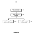
- FIG. 6 illustrates a flowchart of a method for automatically identifying the plurality of pages that were in the volatile memory at crash time, and automatically identifying transactions that were active at the time of the crash;
- FIG. 7 illustrates a time line of a log in the context of an example analysis phase, redo phase and undo phase.
- crash recovery of a computing system includes a volatile memory which has contents lost due to the crash, an intermediate non-volatile memory that (together with the volatile memory) contributes to the active memory of the computing system, and non-volatile storage.
- the recovery occurs by identifying pages that were in the volatile memory at the time of the crash. For each of these pages, the recovery determines whether to recover the page into the volatile memory from either the intermediate non-volatile memory or the storage, and then performs the recovery.
- access speeds for the intermediate non-volatile memory may be much faster than for the storage, and in which much of the pages to be recovered are recovered from the intermediate non-volatile memory, the end-to-end recovery time may be reduced.
- the end-to-end recovery time includes crash recovery time as well as restart or ramp-up time to get the system back up to performance equilibrium.
- Computing systems are now increasingly taking a wide variety of forms. Computing systems may, for example, be handheld devices, appliances, laptop computers, desktop computers, mainframes, distributed computing systems, or even devices that have not conventionally been considered a computing system.
- the term “computing system” is defined broadly as including any device or system (or combination thereof) that includes at least one physical and tangible processor, and a physical and tangible memory capable of having thereon computer-executable instructions that may be executed by the processor.
- the memory may take any form and may depend on the nature and form of the computing system.
- a computing system may be distributed over a network environment and may include multiple constituent computing systems.
- a computing system 100 includes at least one processing unit 102 and memory 104 .
- the memory 104 may be physical system memory, which may be volatile, non-volatile, or some combination of the two.
- the computing system 100 also includes non-volatile memory or storage 106 . If the computing system is distributed, the processing, memory and/or storage capability may be distributed as well.
- the term “module” or “component” can refer to software objects or routines that execute on the computing system. The different components, modules, engines, and services described herein may be implemented as objects or processes that execute on the computing system (e.g., as separate threads).
- embodiments are described with reference to acts that are performed by one or more computing systems. If such acts are implemented in software, one or more processors of the associated computing system that performs the act direct the operation of the computing system in response to having executed computer-executable instructions.
- An example of such an operation involves the manipulation of data.
- the computer-executable instructions (and the manipulated data) may be stored in the memory 104 and/or storage 106 of the computing system 100 .
- Computing system 100 may also contain communication channels 108 that allow the computing system 100 to communicate with other message processors over, for example, network 110 .
- Embodiments described herein may comprise or utilize a special purpose or general-purpose computer including computer hardware, such as, for example, one or more processors and system memory, as discussed in greater detail below.
- Embodiments described herein also include computer program products in the form of one or more physical and other computer-readable media for carrying or storing computer-executable instructions and/or data structures.
- Such computer-readable media can be any available media that can be accessed by a general purpose or special purpose computer system.
- Computer-readable media that store computer-executable instructions are physical storage media.
- Computer-readable media that carry computer-executable instructions are transmission media.
- embodiments of the invention can comprise at least two distinctly different kinds of computer-readable media: computer storage media and transmission media.
- Computer storage media includes RAM, ROM, EEPROM, CD-ROM or other optical disk storage, magnetic disk storage or other magnetic storage devices, or any other tangible medium which can be used to store desired program code means in the form of computer-executable instructions or data structures and which can be accessed by a general purpose or special purpose computer.
- a “network” is defined as one or more data links that enable the transport of electronic data between computer systems and/or modules and/or other electronic devices.
- a network or another communications connection can include a network and/or data links which can be used to carry or desired program code means in the form of computer-executable instructions or data structures and which can be accessed by a general purpose or special purpose computer. Combinations of the above should also be included within the scope of computer-readable media.
- program code means in the form of computer-executable instructions or data structures can be transferred automatically from transmission media to computer storage media (or vice versa).
- computer-executable instructions or data structures received over a network or data link can be buffered in RAM within a network interface module (e.g., a “NIC”), and then eventually transferred to computer system RAM and/or to less volatile computer storage media at a computer system.
- a network interface module e.g., a “NIC”
- NIC network interface module
- computer storage media can be included in computer system components that also (or even primarily) utilize transmission media.
- Computer-executable instructions comprise, for example, instructions and data which, when executed at a processor, cause a general purpose computer, special purpose computer, or special purpose processing device to perform a certain function or group of functions, such as the functions described herein.
- the computer executable instructions may be, for example, binaries, intermediate format instructions such as assembly language, or even source code.
- the invention may be practiced in network computing environments with many types of computer system configurations, including, personal computers, desktop computers, laptop computers, message processors, hand-held devices, multi-processor systems, microprocessor-based or programmable consumer electronics, network PCs, minicomputers, mainframe computers, mobile telephones, PDAs, pagers, routers, switches, and the like.
- the invention may also be practiced in distributed system environments where local and remote computer systems, which are linked (either by hardwired data links, wireless data links, or by a combination of hardwired and wireless data links) through a network, both perform tasks.
- program modules may be located in both local and remote memory storage devices.
- FIG. 2 illustrates a memory hierarchy 200 that includes a volatile memory 201 , non-volatile storage 203 and intermediate non-volatile memory 202 .
- the non-volatile memory 202 and non-volatile storage 203 are shown with thicker cross-hatched borders symbolizing that their contents most typically will survive a power loss. However, the contents of volatile memory 201 rely on power in order to refresh its contents, and thus the contents of the volatile memory 201 will be lost upon a power loss.
- volatile memory 201 would be an example of the volatile portion of the memory 104 of FIG. 1
- intermediate non-volatile memory 202 would be an example of the non-volatile portion of the memory 104 of FIG. 1
- non-volatile storage 203 would be an example of the storage 106 of FIG. 1 .
- the intermediate non-volatile memory 202 may include a single level in the memory hierarchy 200 . However, in some embodiments, there may be more than one intermediate non-volatile memory level in the memory hierarchy 200 as represented by the ellipses 204 . For instance, there might be one portion of the non-volatile memory 202 that has faster access speeds (i.e., higher in the memory hierarchy) than another portion of the non-volatile memory 203 that has lower access speeds (i.e., lower in the memory hierarchy).
- the volatile memory 201 and the non-volatile memory 202 may together comprise the system memory 211 of the computing system, the system memory 211 including the range of addresses that are addressable by the processor(s) of the computing system.
- the system memory 211 includes the working set 210 of pages that are more frequently acted upon by the computing system.
- the working set 210 represents the data and instructions that are being actively used by the computing system in order to perform its current function.
- the working set 210 has the characteristic of having more random accesses.
- the volatile memory 201 has efficient random access speed (hence the term “Random Access Memory” or “RAM”).
- RAM Random Access Memory
- the non-volatile memory 202 is also efficient at random accesses, especially as compared to the storage 203 , which is better suited for sequential access.
- the non-volatile memory 202 and the volatile memory 201 together act as a large random access memory, and together provide the capability of working with a much larger working set 210 than would be possible with the volatile memory 201
- the intermediate non-volatile memory 202 may be storage class memory, such as a solid state disk.
- storage class memory is known in the art, and this description incorporates the known definition of the term.
- a storage class memory has the following properties.
- the memory is solid state
- the memory is randomly accessible
- the memory has lower latency than mechanical disk
- the memory has random I/O throughput greater than mechanical disk because random access is a solid-state electronic process with no mechanical movement of a disk head.
- the storage class memory is non-volatile when used as the non-volatile memory 202 of FIG. 2 .
- a solid state disk is a type of storage class memory and distinguishes from mechanical disk by being a solid state device.
- the solid state disk additionally has the following properties which may also be included in some, but perhaps not all, of other types of storage class memory that may be used with the principles described herein:
- PCM Phase Change Memory
- Ferrous Oxide Ferrous Oxide
- Memristor Other types of storage class memories
- PCM Phase Change Memory
- Ferrous Oxide Ferrous Oxide
- Memristor Memristor
- a “page” is defined as any group of data that is exchanged as an entire entity between the system memory 211 and the storage 203 , and/or between the volatile memory 201 and the non-volatile memory 202 .
- the system memory 211 may have an escalation and eviction mechanism by which pages that are used more frequently tend to be loaded higher in the memory hierarchy, and pages that are used less frequently tend to be evicted to lower levels in the memory hierarchy.
- a copy of the page is retained within the non-volatile memory 202 .
- a copy of the page is retained within the storage 203 .
- FIG. 3 illustrates an example general flow 300 associated with the recovery of the computing system 100 having memory hierarchy 200 .
- startup 301 Upon startup (startup 301 ) after a power loss, the computing system enters an initialization phase 302 , followed by an analysis phase 311 , followed by a redo phase 312 , and in a transactional system, followed by an undo phase 313 .
- ARIES Algorithms for Recovery and Isolation Exploiting Semantics
- ARIES is a recovery algorithm that includes such phases.
- ARIES is designed for database recovery in an environment in which the system memory is entirely rebuilt by reading pages from storage back into memory. The principles described herein build on top of ARIES and reduce recovery time by restoring pages into the volatile memory 201 from the non-volatile memory 202 , as well as from the storage 203 .
- the recovery time may be further reduced especially if the snapshots to non-volatile memory 202 are frequent, and more frequent that the snapshots to storage 203 .
- This checkpointing is an optimization that reduces the size of the log. The checkpointing thus reduces the number of redo and undo actions that have to be performed during crash recovery.
- FIG. 3 will be referred to frequently when describing further recovery details below.
- FIG. 3 is a general diagram, but more specifics regarding what functions might be performed in which phase will be outlined in further detail below.
- normal processing is modified to include two types of snapshots, a less frequent snapshot to storage 203 , and a new more frequent snapshot to non-volatile memory 202 .
- the analysis phase of the ARIES algorithm is modified to formulate the analysis phase 311 of FIG. 3 .
- the redo phase of the ARIES algorithm is modified to formulate the redo phase 312 of FIG. 3 .
- FIG. 4 illustrates a flowchart of a method 400 for recovering from a crash of the computing system in which contents of the volatile memory is lost.
- the method 400 may be performed in the context of the computing system 100 having memory hierarchy 200 and thus the method 400 will be described with frequent reference to FIGS. 1 and 2 . Furthermore, the recovery may follow the general flow 300 of FIG. 3 , and thus the method 400 will also be described with frequent reference to FIG. 3 .
- the method 400 involves automatically identifying pages that were in the volatile memory at the time of the crash (act 401 ). These identified pages will also be the pages that are to be recovered back into the volatile memory 201 in order for the system to recover.
- FIG. 2 recall that the contents of non-volatile memory 202 and non-volatile storage 203 are kept despite the loss of power of the computing system.
- the volatile memory 201 requires power in order to maintain its contents. Accordingly, all of the pages that were in volatile memory 201 are lost when power is lost.
- the identification of the pages that were in the volatile memory at the time of the crash might be performed during the analysis phase 311 in the specific examples provided below.
- the context of box 410 are performed. Specifically, the system automatically determines a source of a recovery version of the page (act 411 ). In other words, the system determines whether to recover the page from the storage 203 or the non-volatile memory 202 of the computing system.
- the recovery source could be the storage 203 like in conventional recovery mechanisms such as ARIES recovery.
- the recovery source might also be the intermediate non-volatile memory 202 . If there are multiple memory levels of the intermediate non-volatile memory 202 , the system may also determine which memory level of the intermediate non-volatile memory 202 to load the page from in cases in which the recover version is located in the intermediate non-volatile memory 202 . Referring to FIG. 3 , the identification of the recovery source might be performed in the analysis phase 311 in the specific example provided below.
- the page is then loaded from the recovery source into the volatile memory (act 412 ). For instance, if the recovery version of the page was located in the non-volatile memory 202 , the page would be loaded into the volatile memory 201 from the non-volatile memory 202 . On the other hand, if the recovery version of the page was located in the storage 203 , the page would be loaded into the volatile memory 201 from the storage 203 . In some instances, during normal operation, when a page is read from the non-volatile memory 202 into the volatile memory 201 , a copy of the page is retained within the non-volatile memory 202 .
- the loading of pages from non-volatile memory 202 or from storage 203 may be part of the redo phase 312 in the specific example provided below.
- the system constructs a mapping (act 413 ) that identifies a location of a recovery version of each page within the intermediate non-volatile memory for each page that has a recovery version within the intermediate non-volatile memory.
- a mapping (act 413 ) that identifies a location of a recovery version of each page within the intermediate non-volatile memory for each page that has a recovery version within the intermediate non-volatile memory.
- the loading of the page from the recovery source uses this mapping to find the location of each recovery version for pages whose recovery version is located within the intermediate non-volatile memory.
- FIG. 5 illustrates a flowchart of a more specific method 500 for recovering from a crash of the computing system in which contents of the volatile memory is lost in the context of the system being a transactional system.
- the method 500 is a specific example of the method 400 of FIG. 4 , but includes some additional acts. Accordingly, the acts 401 , 410 , 412 and 413 of the method 400 are illustrated again within FIG. 5 .
- the system determines which transactions were prepared at the time of the crash (act 511 ). Referring to FIG. 3 , the identification of the pending transactions may be performed during the analysis phase 311 in the example below. The system then prepares each of the transactions that were prepared at crash time (act 512 ) prior to loading the pages from the recovery source into the volatile memory (act 412 ). Referring to FIG. 3 , the preparing of the transactions may be performed as part of the analyses phase 311 .
- the system identifies transactions that were active at crash time (act 521 ). Referring to FIG. 3 , this identification of active transactions may occur as part of the analysis phase 311 in the specific example provided below.
- the system then undoes all actions of each of the active transactions (act 522 ) after all of the pages are recovered into the volatile memory (act 412 ). Referring to FIG. 3 , the undoing of such transactions might be performed as part of the undo phase 313 in the specific example provided herein.
- FIG. 6 illustrates a flowchart of a method 600 for automatically identifying the plurality of pages that were in the volatile memory at crash time, and automatically identifying transactions that were active at the time of the crash.
- the method 600 represents one example of the act 401 of FIGS. 4 and 5 (in the case of identifying pages that were in volatile memory at crash time) and act 521 of FIG. 5 (in the case of identifying transactions active at crash time).
- the method 600 may be performed during the analysis phase 311 in the specific example provided below.
- the system identifies the last log sequence number flushed to a log in the non-volatile storage (act 601 ), and then sequentially reviews the log entries of the log from this last flushed log sequence number (act 602 ). Based the analysis of the log entries, the system identifies the pages that were in the volatile memory at crash time (act 603 ), and also identifies transactions that were active at the time of the crash (act 604 ).
- FIG. 7 illustrates the three phases including the analysis phase 720 , the redo phase 730 and the undo phase 740 in the context of a log timeline 710 .
- the analysis phase 720 , the redo phase 730 and the undo phase 740 of FIG. 7 are examples of the analysis phase 311 , the redo phase 312 , and the undo phase 313 , respectively, of FIG. 3 .
- the computing system maintains a log of significant events. For instance, in FIG. 7 , amongst other things, the computing system logged the start of active transactions, when checkpoints occur, when a page becomes dirty (i.e., is written to in the system memory 211 without being written to the storage 203 ), and so forth.
- the event is assigned some type of identification in which the order of events can be derived based on the assigned identification. For instance, the identification might be a log sequence number in which the log sequence number is incremented for each event recorded. Thus, events that are later in the log have a higher log sequence number than events that are earlier in the log.
- the computing system also writes certain items of information into a portion of storage that is accessible during boot time. For instance, the information may be written into the boot block of the computing system.
- the information includes the log sequence number of the last checkpoint, as well as a globally unique identifier of the last page file flushed from the system memory 211 into the storage 203 .
- the page file includes all of the pages included within the non-volatile memory 202 .
- the globally unique identifier is altered each time a page in the page file is altered (e.g., each time the page file is created, deleted, formatted with a new version, or any other alteration) in the non-volatile memory 202 .
- the analysis phase 720 has a number of functions including identifying 1) at what point in the log the redo phase 730 should begin, 2) what pages need to be redone (i.e., loaded into volatile memory 201 ), 3) what transactions were active at the time of the crash, and 4) what transactions were prepared at the time of the crash.
- the log is scanned to identify pages that need to be loaded into non-volatile memory.
- the analysis first determines where to start scanning the log moving forward.
- the globally unique identifier of the page file in the non-volatile memory 202 is compared against the globally unique identifier of the last page file flushed to storage 203 . If there is not a match, then the log is scanned from the penultimate snapshot to the storage 203 , much as would be performed during normal ARIES recovery.
- the snapshots to the non-volatile memory 202 may be used to perform recovery. Accordingly, the scan forward (to identify what pages are to be loaded into volatile memory 201 ) is begun at the penultimate snapshot to non-volatile memory 202 .
- the scan forward to identify what pages are to be loaded into volatile memory 201
- processing normally associated with the analysis phase 720 may also be performed. For instance, active transactions may be identified, the starting point for the redo phase 730 is identified, and the transactions are identified that were active or prepared at the time of the crash are identified.
- a dirty page table is constructed, which is initially empty at the beginning of the scan.
- the ultimate endpoint of the dirty page table is that the dirty page table includes all pages whose minimum log sequence number is greater than the log sequence number of the last flush to the log(i.e., minRecoveryLSN) which is read from the boot block.
- the dirty page table also indicates where the most recent version of the page is located, whether it be on the non-volatile memory 202 or whether it be on the storage 203 .
- redo phase 730 all of the prepared transactions identified in the analysis phase 720 are first prepared. Then, all of the pages beginning at the oldest dirty page in the dirty page table (represented by element 714 in FIG. 7 ) are loaded from the appropriate location identified in the analysis phase 720 . This may be performed in according with the normal redo phase of an ARIES recovery, except that now, the appropriate source for each page to be loaded into the volatile memory may be either the storage 203 , but likely more often, the non-volatile memory 202 . Again, since randomly accessible loads from the non-volatile memory 202 are much faster, this speeds up recovery significant. Conventional recovery involves mainly random accesses to retrieve pages from disk media and sequential scans of the log and journal files.
- the log 710 is reverse scanned from the end of the log(element 716 ) all the way back to the beginning of the oldest active transaction (element 711 ). For any logged actions that are part of an active transaction, those actions are undone.
Landscapes
- Engineering & Computer Science (AREA)
- Theoretical Computer Science (AREA)
- Quality & Reliability (AREA)
- Physics & Mathematics (AREA)
- General Engineering & Computer Science (AREA)
- General Physics & Mathematics (AREA)
- Health & Medical Sciences (AREA)
- Biomedical Technology (AREA)
- Information Retrieval, Db Structures And Fs Structures Therefor (AREA)
- Techniques For Improving Reliability Of Storages (AREA)
- Memory System Of A Hierarchy Structure (AREA)
Priority Applications (6)
| Application Number | Priority Date | Filing Date | Title |
|---|---|---|---|
| US14/069,028 US9558080B2 (en) | 2013-10-31 | 2013-10-31 | Crash recovery using non-volatile memory |
| BR112016007142-5A BR112016007142B1 (pt) | 2013-10-31 | 2014-10-27 | Método para recuperar de uma falha de um sistema de computação no qual o conteúdo de uma memória volátil é perdido |
| EP14796356.5A EP3063631B1 (de) | 2013-10-31 | 2014-10-27 | Systemabsturzwiederherstellung mit nichtflüchtigem speicher |
| CN201480060820.8A CN105706061B (zh) | 2013-10-31 | 2014-10-27 | 使用非易失性存储器的崩溃恢复 |
| PCT/US2014/062313 WO2015065863A2 (en) | 2013-10-31 | 2014-10-27 | Crash recovery using non-volatile memory |
| US15/411,853 US10437662B2 (en) | 2013-10-31 | 2017-01-20 | Crash recovery using non-volatile memory |
Applications Claiming Priority (1)
| Application Number | Priority Date | Filing Date | Title |
|---|---|---|---|
| US14/069,028 US9558080B2 (en) | 2013-10-31 | 2013-10-31 | Crash recovery using non-volatile memory |
Related Child Applications (1)
| Application Number | Title | Priority Date | Filing Date |
|---|---|---|---|
| US15/411,853 Continuation US10437662B2 (en) | 2013-10-31 | 2017-01-20 | Crash recovery using non-volatile memory |
Publications (2)
| Publication Number | Publication Date |
|---|---|
| US20150121126A1 US20150121126A1 (en) | 2015-04-30 |
| US9558080B2 true US9558080B2 (en) | 2017-01-31 |
Family
ID=51871309
Family Applications (2)
| Application Number | Title | Priority Date | Filing Date |
|---|---|---|---|
| US14/069,028 Active 2034-03-14 US9558080B2 (en) | 2013-10-31 | 2013-10-31 | Crash recovery using non-volatile memory |
| US15/411,853 Active 2034-09-17 US10437662B2 (en) | 2013-10-31 | 2017-01-20 | Crash recovery using non-volatile memory |
Family Applications After (1)
| Application Number | Title | Priority Date | Filing Date |
|---|---|---|---|
| US15/411,853 Active 2034-09-17 US10437662B2 (en) | 2013-10-31 | 2017-01-20 | Crash recovery using non-volatile memory |
Country Status (5)
| Country | Link |
|---|---|
| US (2) | US9558080B2 (de) |
| EP (1) | EP3063631B1 (de) |
| CN (1) | CN105706061B (de) |
| BR (1) | BR112016007142B1 (de) |
| WO (1) | WO2015065863A2 (de) |
Cited By (4)
| Publication number | Priority date | Publication date | Assignee | Title |
|---|---|---|---|---|
| US20170132071A1 (en) * | 2013-10-31 | 2017-05-11 | Microsoft Technology Licensing, Llc | Crash recovery using non-volatile memory |
| US20180240111A1 (en) * | 2017-02-21 | 2018-08-23 | Mastercard International Incorporated | Security architecture for device applications |
| US20180336088A1 (en) * | 2017-05-19 | 2018-11-22 | SK Hynix Inc. | Data storage device and operating method thereof |
| US12547489B2 (en) * | 2024-05-29 | 2026-02-10 | Dell Products L.P. | Automated system crash analysis and remediation |
Families Citing this family (16)
| Publication number | Priority date | Publication date | Assignee | Title |
|---|---|---|---|---|
| KR101676932B1 (ko) * | 2012-03-02 | 2016-11-16 | 휴렛 팩커드 엔터프라이즈 디벨롭먼트 엘피 | 멀티-레벨 셀을 사용하여 버전화되는 메모리들 |
| US10402259B2 (en) * | 2015-05-29 | 2019-09-03 | Nxp Usa, Inc. | Systems and methods for resource leakage recovery in processor hardware engines |
| US20180189144A1 (en) * | 2015-06-16 | 2018-07-05 | Iucf-Hyu (Industry-University Cooperation Foundation Hanyang University) | Apparatus and method for memory storage to protect data-loss after power loss |
| US9952931B2 (en) | 2016-01-19 | 2018-04-24 | Microsoft Technology Licensing, Llc | Versioned records management using restart era |
| US10296418B2 (en) * | 2016-01-19 | 2019-05-21 | Microsoft Technology Licensing, Llc | Versioned records management using restart era |
| US9858151B1 (en) | 2016-10-03 | 2018-01-02 | International Business Machines Corporation | Replaying processing of a restarted application |
| CN108958959B (zh) * | 2017-05-18 | 2022-04-12 | 北京京东尚科信息技术有限公司 | 检测hive数据表的方法和装置 |
| KR102485812B1 (ko) * | 2017-12-19 | 2023-01-09 | 에스케이하이닉스 주식회사 | 메모리 시스템과 메모리 시스템의 동작방법 및 메모리 시스템을 포함하는 데이터 처리 시스템 |
| US10776208B2 (en) | 2018-07-18 | 2020-09-15 | EMC IP Holding Company LLC | Distributed memory checkpointing using storage class memory systems |
| US11003549B2 (en) * | 2018-07-25 | 2021-05-11 | Microsoft Technology Licensing, Llc | Constant time database recovery |
| US11188516B2 (en) | 2018-08-24 | 2021-11-30 | Oracle International Corproation | Providing consistent database recovery after database failure for distributed databases with non-durable storage leveraging background synchronization point |
| US11099948B2 (en) * | 2018-09-21 | 2021-08-24 | Microsoft Technology Licensing, Llc | Persistent storage segment caching for data recovery |
| US11334445B2 (en) * | 2018-10-19 | 2022-05-17 | Oracle International Corporation | Using non-volatile memory to improve the availability of an in-memory database |
| KR102730660B1 (ko) * | 2019-01-15 | 2024-11-15 | 에스케이하이닉스 주식회사 | 저장 장치, 컨트롤러 및 저장 장치의 동작 방법 |
| US11681657B2 (en) * | 2019-07-31 | 2023-06-20 | EMC IP Holding Company, LLC | System and method for parallel flushing with bucketized data |
| US20260220050A1 (en) * | 2025-01-30 | 2026-07-30 | Dell Products L.P. | System and Method for Recovering Unflushed User Data Pages from a Log Memory System |
Citations (11)
| Publication number | Priority date | Publication date | Assignee | Title |
|---|---|---|---|---|
| GB2256952A (en) | 1991-06-18 | 1992-12-23 | Digital Equipment Corp | Computer transaction processing |
| US5524205A (en) * | 1990-06-29 | 1996-06-04 | Oracle Corporation | Methods and apparatus for optimizing undo log usage |
| US20050081091A1 (en) | 2003-09-29 | 2005-04-14 | International Business Machines (Ibm) Corporation | Method, system and article of manufacture for recovery from a failure in a cascading PPRC system |
| US20060059209A1 (en) | 2004-09-14 | 2006-03-16 | Lashley Scott D | Crash recovery by logging extra data |
| US20100199045A1 (en) * | 2009-02-03 | 2010-08-05 | International Buisness Machines Corporation | Store-to-load forwarding mechanism for processor runahead mode operation |
| US20100223243A1 (en) | 2009-02-27 | 2010-09-02 | International Business Machines Corporation | Automatic detection and correction of hot pages in a database system |
| US20110219169A1 (en) | 2010-03-04 | 2011-09-08 | Microsoft Corporation | Buffer Pool Extension for Database Server |
| US20120109895A1 (en) | 2010-10-28 | 2012-05-03 | Microsoft Corporation | Versatile in-memory database recovery |
| US20130042156A1 (en) * | 2011-08-12 | 2013-02-14 | Oracle International Corporation | Utilizing multiple storage devices to reduce write latency for database logging |
| US20130191578A1 (en) * | 2012-01-20 | 2013-07-25 | Seagate Technology Llc | Storing cached data in over-provisioned memory in response to power loss |
| US20140019688A1 (en) * | 2012-07-13 | 2014-01-16 | iAnywhere Solutions | Solid State Drives as a Persistent Cache for Database Systems |
Family Cites Families (9)
| Publication number | Priority date | Publication date | Assignee | Title |
|---|---|---|---|---|
| US5918225A (en) * | 1993-04-16 | 1999-06-29 | Sybase, Inc. | SQL-based database system with improved indexing methodology |
| US8452929B2 (en) * | 2005-04-21 | 2013-05-28 | Violin Memory Inc. | Method and system for storage of data in non-volatile media |
| US7765361B2 (en) * | 2006-11-21 | 2010-07-27 | Microsoft Corporation | Enforced transaction system recoverability on media without write-through |
| US8370562B2 (en) * | 2007-02-25 | 2013-02-05 | Sandisk Il Ltd. | Interruptible cache flushing in flash memory systems |
| US7904427B2 (en) * | 2008-01-11 | 2011-03-08 | Microsoft Corporation | Lazier timestamping in a transaction time database |
| US9361044B2 (en) * | 2011-03-28 | 2016-06-07 | Western Digital Technologies, Inc. | Power-safe data management system |
| US8984247B1 (en) * | 2012-05-10 | 2015-03-17 | Western Digital Technologies, Inc. | Storing and reconstructing mapping table data in a data storage system |
| US9423978B2 (en) * | 2013-05-08 | 2016-08-23 | Nexgen Storage, Inc. | Journal management |
| US9558080B2 (en) * | 2013-10-31 | 2017-01-31 | Microsoft Technology Licensing, Llc | Crash recovery using non-volatile memory |
-
2013
- 2013-10-31 US US14/069,028 patent/US9558080B2/en active Active
-
2014
- 2014-10-27 EP EP14796356.5A patent/EP3063631B1/de active Active
- 2014-10-27 WO PCT/US2014/062313 patent/WO2015065863A2/en not_active Ceased
- 2014-10-27 BR BR112016007142-5A patent/BR112016007142B1/pt active IP Right Grant
- 2014-10-27 CN CN201480060820.8A patent/CN105706061B/zh active Active
-
2017
- 2017-01-20 US US15/411,853 patent/US10437662B2/en active Active
Patent Citations (11)
| Publication number | Priority date | Publication date | Assignee | Title |
|---|---|---|---|---|
| US5524205A (en) * | 1990-06-29 | 1996-06-04 | Oracle Corporation | Methods and apparatus for optimizing undo log usage |
| GB2256952A (en) | 1991-06-18 | 1992-12-23 | Digital Equipment Corp | Computer transaction processing |
| US20050081091A1 (en) | 2003-09-29 | 2005-04-14 | International Business Machines (Ibm) Corporation | Method, system and article of manufacture for recovery from a failure in a cascading PPRC system |
| US20060059209A1 (en) | 2004-09-14 | 2006-03-16 | Lashley Scott D | Crash recovery by logging extra data |
| US20100199045A1 (en) * | 2009-02-03 | 2010-08-05 | International Buisness Machines Corporation | Store-to-load forwarding mechanism for processor runahead mode operation |
| US20100223243A1 (en) | 2009-02-27 | 2010-09-02 | International Business Machines Corporation | Automatic detection and correction of hot pages in a database system |
| US20110219169A1 (en) | 2010-03-04 | 2011-09-08 | Microsoft Corporation | Buffer Pool Extension for Database Server |
| US20120109895A1 (en) | 2010-10-28 | 2012-05-03 | Microsoft Corporation | Versatile in-memory database recovery |
| US20130042156A1 (en) * | 2011-08-12 | 2013-02-14 | Oracle International Corporation | Utilizing multiple storage devices to reduce write latency for database logging |
| US20130191578A1 (en) * | 2012-01-20 | 2013-07-25 | Seagate Technology Llc | Storing cached data in over-provisioned memory in response to power loss |
| US20140019688A1 (en) * | 2012-07-13 | 2014-01-16 | iAnywhere Solutions | Solid State Drives as a Persistent Cache for Database Systems |
Non-Patent Citations (6)
| Title |
|---|
| "International Search Report & Written Opinion for PCT Application No. PCT/US2014/062313", Mailed Date: May 4, 2015, 15 Pages. |
| Alvarez, Victor, "SQL Server-Checkpoint", Retrieved on: May 21, 2012, Available at: http://sqlpost.blogspot.in/2009/06/sql-server-checkpoint.html. |
| Bhattacharjee, et al., "Enhancing Recovery Using an SSD Buffer Pool Extension", In Proceedings of the Seventh International Workshop on Data Management on New Hardware, Jun. 13, 2011, pp. 10-16. |
| Do, et al., "Turbocharging DBMS Buffer Pool Using SSDs", In Proceedings of the International Conference on Management of Data, Jun. 12, 2011, pp. 1113-1124. |
| Mohan, et al., "ARIES: A Transaction Recovery Method Supporting Fine-Granularity Locking and Partial Rollbacks Using Write-Ahead Logging", ACM Transactions on Database Systems, vol. 17, No. 1, Mar. 1992, pp. 94-162. |
| Wikipedia page of "CPU cache" from date Oct. 26, 2013, retrieved using the way-back-machine, from https://web.archive.org/web/20131026231549/http://en.wikipedia.org/wiki/CPU-Cache#Multi-level-caches. * |
Cited By (6)
| Publication number | Priority date | Publication date | Assignee | Title |
|---|---|---|---|---|
| US20170132071A1 (en) * | 2013-10-31 | 2017-05-11 | Microsoft Technology Licensing, Llc | Crash recovery using non-volatile memory |
| US10437662B2 (en) * | 2013-10-31 | 2019-10-08 | Microsoft Technology Licensing, Llc | Crash recovery using non-volatile memory |
| US20180240111A1 (en) * | 2017-02-21 | 2018-08-23 | Mastercard International Incorporated | Security architecture for device applications |
| US20180336088A1 (en) * | 2017-05-19 | 2018-11-22 | SK Hynix Inc. | Data storage device and operating method thereof |
| US10649840B2 (en) * | 2017-05-19 | 2020-05-12 | SK Hynix Inc. | Data storage device performing recovery operation after sudden power-off and operating method thereof |
| US12547489B2 (en) * | 2024-05-29 | 2026-02-10 | Dell Products L.P. | Automated system crash analysis and remediation |
Also Published As
| Publication number | Publication date |
|---|---|
| CN105706061A (zh) | 2016-06-22 |
| US20170132071A1 (en) | 2017-05-11 |
| BR112016007142B1 (pt) | 2022-01-25 |
| US10437662B2 (en) | 2019-10-08 |
| CN105706061B (zh) | 2019-01-08 |
| WO2015065863A3 (en) | 2015-07-09 |
| BR112016007142A8 (pt) | 2020-03-03 |
| US20150121126A1 (en) | 2015-04-30 |
| EP3063631A2 (de) | 2016-09-07 |
| WO2015065863A2 (en) | 2015-05-07 |
| EP3063631B1 (de) | 2017-08-09 |
| BR112016007142A2 (pt) | 2017-08-01 |
Similar Documents
| Publication | Publication Date | Title |
|---|---|---|
| US10437662B2 (en) | Crash recovery using non-volatile memory | |
| CN102722449B (zh) | 基于SSD的Key-Value型本地存储方法及系统 | |
| CN105630409B (zh) | 使用存储器内阵列和盘上页结构的双重数据存储 | |
| US10176190B2 (en) | Data integrity and loss resistance in high performance and high capacity storage deduplication | |
| US10042910B2 (en) | Database table re-partitioning using two active partition specifications | |
| US9430333B2 (en) | Recovery of application from snapshot | |
| US20140115244A1 (en) | Apparatus, system and method for providing a persistent level-two cache | |
| KR20160023871A (ko) | 다중 액세스 방법을 위한 래치-프리, 로그-구조 스토리지 | |
| US10114765B2 (en) | Automatic recovery of application cache warmth | |
| CN106503051A (zh) | 一种基于元数据分类的贪婪预取型数据恢复系统及恢复方法 | |
| CN103595797A (zh) | 一种分布式存储系统中的缓存方法 | |
| KR20200060220A (ko) | 비휘발성 메모리 기반 파일 시스템 및 이를 이용한 데이터 갱신 방법 | |
| Son et al. | SSD-assisted backup and recovery for database systems | |
| US11593352B2 (en) | Cloud-native object storage for page-based relational database | |
| US10915403B2 (en) | Versioned records management using restart era | |
| KR101809679B1 (ko) | 데이터베이스의 일관성 유지를 위한 컴퓨팅 장치 및 방법 | |
| US10482013B2 (en) | Eliding memory page writes upon eviction after page modification | |
| US9575990B2 (en) | Partitioning data within a distributed data storage system using virtual file links | |
| EP4002148A1 (de) | Cloud-native objektspeicherung für seitenbasierte relationale datenbank | |
| Saha et al. | LATTICE: Efficient In-Memory DNN Model Versioning | |
| US11789951B2 (en) | Storage of data structures | |
| US20250117373A1 (en) | Search and analytics engine with object store persistence | |
| US11099948B2 (en) | Persistent storage segment caching for data recovery | |
| HK1181150B (en) | Hybrid oltp and olap high performance database system | |
| HK1181150A (en) | Hybrid oltp and olap high performance database system |
Legal Events
| Date | Code | Title | Description |
|---|---|---|---|
| AS | Assignment |
Owner name: MICROSOFT CORPORATION, WASHINGTON Free format text: ASSIGNMENT OF ASSIGNORS INTEREST;ASSIGNORS:BRADSHAW, DEXTER PAUL;CELIS, PEDRO;REEL/FRAME:031524/0479 Effective date: 20131031 |
|
| AS | Assignment |
Owner name: MICROSOFT TECHNOLOGY LICENSING, LLC, WASHINGTON Free format text: ASSIGNMENT OF ASSIGNORS INTEREST;ASSIGNOR:MICROSOFT CORPORATION;REEL/FRAME:034747/0417 Effective date: 20141014 Owner name: MICROSOFT TECHNOLOGY LICENSING, LLC, WASHINGTON Free format text: ASSIGNMENT OF ASSIGNORS INTEREST;ASSIGNOR:MICROSOFT CORPORATION;REEL/FRAME:039025/0454 Effective date: 20141014 |
|
| FEPP | Fee payment procedure |
Free format text: PAYOR NUMBER ASSIGNED (ORIGINAL EVENT CODE: ASPN); ENTITY STATUS OF PATENT OWNER: LARGE ENTITY |
|
| STCF | Information on status: patent grant |
Free format text: PATENTED CASE |
|
| MAFP | Maintenance fee payment |
Free format text: PAYMENT OF MAINTENANCE FEE, 4TH YEAR, LARGE ENTITY (ORIGINAL EVENT CODE: M1551); ENTITY STATUS OF PATENT OWNER: LARGE ENTITY Year of fee payment: 4 |
|
| MAFP | Maintenance fee payment |
Free format text: PAYMENT OF MAINTENANCE FEE, 8TH YEAR, LARGE ENTITY (ORIGINAL EVENT CODE: M1552); ENTITY STATUS OF PATENT OWNER: LARGE ENTITY Year of fee payment: 8 |