US9577402B2 - Variable-wavelength light source - Google Patents
Variable-wavelength light source Download PDFInfo
- Publication number
- US9577402B2 US9577402B2 US14/909,767 US201414909767A US9577402B2 US 9577402 B2 US9577402 B2 US 9577402B2 US 201414909767 A US201414909767 A US 201414909767A US 9577402 B2 US9577402 B2 US 9577402B2
- Authority
- US
- United States
- Prior art keywords
- mirror
- filter
- wavelength
- light
- variable
- Prior art date
- Legal status (The legal status is an assumption and is not a legal conclusion. Google has not performed a legal analysis and makes no representation as to the accuracy of the status listed.)
- Expired - Fee Related
Links
Images




Classifications
-
- H—ELECTRICITY
- H01—ELECTRIC ELEMENTS
- H01S—DEVICES USING THE PROCESS OF LIGHT AMPLIFICATION BY STIMULATED EMISSION OF RADIATION [LASER] TO AMPLIFY OR GENERATE LIGHT; DEVICES USING STIMULATED EMISSION OF ELECTROMAGNETIC RADIATION IN WAVE RANGES OTHER THAN OPTICAL
- H01S3/00—Lasers, i.e. devices using stimulated emission of electromagnetic radiation in the infrared, visible or ultraviolet wave range
- H01S3/10—Controlling the intensity, frequency, phase, polarisation or direction of the emitted radiation, e.g. switching, gating, modulating or demodulating
- H01S3/106—Controlling the intensity, frequency, phase, polarisation or direction of the emitted radiation, e.g. switching, gating, modulating or demodulating by controlling devices placed within the cavity
- H01S3/1062—Controlling the intensity, frequency, phase, polarisation or direction of the emitted radiation, e.g. switching, gating, modulating or demodulating by controlling devices placed within the cavity using a controlled passive interferometer, e.g. a Fabry-Perot etalon
-
- G—PHYSICS
- G01—MEASURING; TESTING
- G01J—MEASUREMENT OF INTENSITY, VELOCITY, SPECTRAL CONTENT, POLARISATION, PHASE OR PULSE CHARACTERISTICS OF INFRARED, VISIBLE OR ULTRAVIOLET LIGHT; COLORIMETRY; RADIATION PYROMETRY
- G01J3/00—Spectrometry; Spectrophotometry; Monochromators; Measuring colours
- G01J3/02—Details
- G01J3/10—Arrangements of light sources specially adapted for spectrometry or colorimetry
-
- G—PHYSICS
- G02—OPTICS
- G02B—OPTICAL ELEMENTS, SYSTEMS OR APPARATUS
- G02B26/00—Optical devices or arrangements for the control of light using movable or deformable optical elements
- G02B26/001—Optical devices or arrangements for the control of light using movable or deformable optical elements based on interference in an adjustable optical cavity
-
- H—ELECTRICITY
- H01—ELECTRIC ELEMENTS
- H01S—DEVICES USING THE PROCESS OF LIGHT AMPLIFICATION BY STIMULATED EMISSION OF RADIATION [LASER] TO AMPLIFY OR GENERATE LIGHT; DEVICES USING STIMULATED EMISSION OF ELECTROMAGNETIC RADIATION IN WAVE RANGES OTHER THAN OPTICAL
- H01S3/00—Lasers, i.e. devices using stimulated emission of electromagnetic radiation in the infrared, visible or ultraviolet wave range
- H01S3/05—Construction or shape of optical resonators; Accommodation of active medium therein; Shape of active medium
- H01S3/06—Construction or shape of active medium
- H01S3/07—Construction or shape of active medium consisting of a plurality of parts, e.g. segments
-
- H—ELECTRICITY
- H01—ELECTRIC ELEMENTS
- H01S—DEVICES USING THE PROCESS OF LIGHT AMPLIFICATION BY STIMULATED EMISSION OF RADIATION [LASER] TO AMPLIFY OR GENERATE LIGHT; DEVICES USING STIMULATED EMISSION OF ELECTROMAGNETIC RADIATION IN WAVE RANGES OTHER THAN OPTICAL
- H01S3/00—Lasers, i.e. devices using stimulated emission of electromagnetic radiation in the infrared, visible or ultraviolet wave range
- H01S3/05—Construction or shape of optical resonators; Accommodation of active medium therein; Shape of active medium
- H01S3/08—Construction or shape of optical resonators or components thereof
- H01S3/08018—Mode suppression
- H01S3/08022—Longitudinal modes
- H01S3/08027—Longitudinal modes by a filter, e.g. a Fabry-Perot filter is used for wavelength setting
-
- H—ELECTRICITY
- H01—ELECTRIC ELEMENTS
- H01S—DEVICES USING THE PROCESS OF LIGHT AMPLIFICATION BY STIMULATED EMISSION OF RADIATION [LASER] TO AMPLIFY OR GENERATE LIGHT; DEVICES USING STIMULATED EMISSION OF ELECTROMAGNETIC RADIATION IN WAVE RANGES OTHER THAN OPTICAL
- H01S3/00—Lasers, i.e. devices using stimulated emission of electromagnetic radiation in the infrared, visible or ultraviolet wave range
- H01S3/05—Construction or shape of optical resonators; Accommodation of active medium therein; Shape of active medium
- H01S3/08—Construction or shape of optical resonators or components thereof
- H01S3/08086—Multiple-wavelength emission
- H01S3/0809—Two-wavelenghth emission
-
- H—ELECTRICITY
- H01—ELECTRIC ELEMENTS
- H01S—DEVICES USING THE PROCESS OF LIGHT AMPLIFICATION BY STIMULATED EMISSION OF RADIATION [LASER] TO AMPLIFY OR GENERATE LIGHT; DEVICES USING STIMULATED EMISSION OF ELECTROMAGNETIC RADIATION IN WAVE RANGES OTHER THAN OPTICAL
- H01S3/00—Lasers, i.e. devices using stimulated emission of electromagnetic radiation in the infrared, visible or ultraviolet wave range
- H01S3/05—Construction or shape of optical resonators; Accommodation of active medium therein; Shape of active medium
- H01S3/08—Construction or shape of optical resonators or components thereof
- H01S3/081—Construction or shape of optical resonators or components thereof comprising three or more reflectors
- H01S3/082—Construction or shape of optical resonators or components thereof comprising three or more reflectors defining a plurality of resonators, e.g. for mode selection or suppression
- H01S3/0823—Construction or shape of optical resonators or components thereof comprising three or more reflectors defining a plurality of resonators, e.g. for mode selection or suppression incorporating a dispersive element, e.g. a prism for wavelength selection
-
- H—ELECTRICITY
- H01—ELECTRIC ELEMENTS
- H01S—DEVICES USING THE PROCESS OF LIGHT AMPLIFICATION BY STIMULATED EMISSION OF RADIATION [LASER] TO AMPLIFY OR GENERATE LIGHT; DEVICES USING STIMULATED EMISSION OF ELECTROMAGNETIC RADIATION IN WAVE RANGES OTHER THAN OPTICAL
- H01S5/00—Semiconductor lasers
- H01S5/10—Construction or shape of the optical resonator, e.g. extended or external cavity, coupled cavities, bent-guide, varying width, thickness or composition of the active region
- H01S5/1092—Multi-wavelength lasing
-
- H—ELECTRICITY
- H01—ELECTRIC ELEMENTS
- H01S—DEVICES USING THE PROCESS OF LIGHT AMPLIFICATION BY STIMULATED EMISSION OF RADIATION [LASER] TO AMPLIFY OR GENERATE LIGHT; DEVICES USING STIMULATED EMISSION OF ELECTROMAGNETIC RADIATION IN WAVE RANGES OTHER THAN OPTICAL
- H01S5/00—Semiconductor lasers
- H01S5/10—Construction or shape of the optical resonator, e.g. extended or external cavity, coupled cavities, bent-guide, varying width, thickness or composition of the active region
- H01S5/14—External cavity lasers
- H01S5/141—External cavity lasers using a wavelength selective device, e.g. a grating or etalon
- H01S5/142—External cavity lasers using a wavelength selective device, e.g. a grating or etalon which comprises an additional resonator
-
- H—ELECTRICITY
- H01—ELECTRIC ELEMENTS
- H01S—DEVICES USING THE PROCESS OF LIGHT AMPLIFICATION BY STIMULATED EMISSION OF RADIATION [LASER] TO AMPLIFY OR GENERATE LIGHT; DEVICES USING STIMULATED EMISSION OF ELECTROMAGNETIC RADIATION IN WAVE RANGES OTHER THAN OPTICAL
- H01S3/00—Lasers, i.e. devices using stimulated emission of electromagnetic radiation in the infrared, visible or ultraviolet wave range
- H01S3/02—Constructional details
- H01S3/025—Constructional details of solid state lasers, e.g. housings or mountings
-
- H—ELECTRICITY
- H01—ELECTRIC ELEMENTS
- H01S—DEVICES USING THE PROCESS OF LIGHT AMPLIFICATION BY STIMULATED EMISSION OF RADIATION [LASER] TO AMPLIFY OR GENERATE LIGHT; DEVICES USING STIMULATED EMISSION OF ELECTROMAGNETIC RADIATION IN WAVE RANGES OTHER THAN OPTICAL
- H01S3/00—Lasers, i.e. devices using stimulated emission of electromagnetic radiation in the infrared, visible or ultraviolet wave range
- H01S3/05—Construction or shape of optical resonators; Accommodation of active medium therein; Shape of active medium
- H01S3/08—Construction or shape of optical resonators or components thereof
- H01S3/08059—Constructional details of the reflector, e.g. shape
-
- H—ELECTRICITY
- H01—ELECTRIC ELEMENTS
- H01S—DEVICES USING THE PROCESS OF LIGHT AMPLIFICATION BY STIMULATED EMISSION OF RADIATION [LASER] TO AMPLIFY OR GENERATE LIGHT; DEVICES USING STIMULATED EMISSION OF ELECTROMAGNETIC RADIATION IN WAVE RANGES OTHER THAN OPTICAL
- H01S3/00—Lasers, i.e. devices using stimulated emission of electromagnetic radiation in the infrared, visible or ultraviolet wave range
- H01S3/05—Construction or shape of optical resonators; Accommodation of active medium therein; Shape of active medium
- H01S3/08—Construction or shape of optical resonators or components thereof
- H01S3/08086—Multiple-wavelength emission
-
- H—ELECTRICITY
- H01—ELECTRIC ELEMENTS
- H01S—DEVICES USING THE PROCESS OF LIGHT AMPLIFICATION BY STIMULATED EMISSION OF RADIATION [LASER] TO AMPLIFY OR GENERATE LIGHT; DEVICES USING STIMULATED EMISSION OF ELECTROMAGNETIC RADIATION IN WAVE RANGES OTHER THAN OPTICAL
- H01S3/00—Lasers, i.e. devices using stimulated emission of electromagnetic radiation in the infrared, visible or ultraviolet wave range
- H01S3/10—Controlling the intensity, frequency, phase, polarisation or direction of the emitted radiation, e.g. switching, gating, modulating or demodulating
- H01S3/105—Controlling the intensity, frequency, phase, polarisation or direction of the emitted radiation, e.g. switching, gating, modulating or demodulating by controlling the mutual position or the reflecting properties of the reflectors of the cavity, e.g. by controlling the cavity length
-
- H01S5/02248—
-
- H—ELECTRICITY
- H01—ELECTRIC ELEMENTS
- H01S—DEVICES USING THE PROCESS OF LIGHT AMPLIFICATION BY STIMULATED EMISSION OF RADIATION [LASER] TO AMPLIFY OR GENERATE LIGHT; DEVICES USING STIMULATED EMISSION OF ELECTROMAGNETIC RADIATION IN WAVE RANGES OTHER THAN OPTICAL
- H01S5/00—Semiconductor lasers
- H01S5/02—Structural details or components not essential to laser action
- H01S5/022—Mountings; Housings
- H01S5/0225—Out-coupling of light
- H01S5/02253—Out-coupling of light using lenses
-
- H01S5/02288—
-
- H—ELECTRICITY
- H01—ELECTRIC ELEMENTS
- H01S—DEVICES USING THE PROCESS OF LIGHT AMPLIFICATION BY STIMULATED EMISSION OF RADIATION [LASER] TO AMPLIFY OR GENERATE LIGHT; DEVICES USING STIMULATED EMISSION OF ELECTROMAGNETIC RADIATION IN WAVE RANGES OTHER THAN OPTICAL
- H01S5/00—Semiconductor lasers
- H01S5/02—Structural details or components not essential to laser action
- H01S5/022—Mountings; Housings
- H01S5/023—Mount members, e.g. sub-mount members
- H01S5/02325—Mechanically integrated components on mount members or optical micro-benches
-
- H—ELECTRICITY
- H01—ELECTRIC ELEMENTS
- H01S—DEVICES USING THE PROCESS OF LIGHT AMPLIFICATION BY STIMULATED EMISSION OF RADIATION [LASER] TO AMPLIFY OR GENERATE LIGHT; DEVICES USING STIMULATED EMISSION OF ELECTROMAGNETIC RADIATION IN WAVE RANGES OTHER THAN OPTICAL
- H01S5/00—Semiconductor lasers
- H01S5/10—Construction or shape of the optical resonator, e.g. extended or external cavity, coupled cavities, bent-guide, varying width, thickness or composition of the active region
- H01S5/18—Surface-emitting [SE] lasers, e.g. having both horizontal and vertical cavities
- H01S5/183—Surface-emitting [SE] lasers, e.g. having both horizontal and vertical cavities having only vertical cavities, e.g. vertical cavity surface-emitting lasers [VCSEL]
Definitions
- the present invention relates to a variable-wavelength light source.
- variable-wavelength light sources are used as communication lasers for wavelength multiplex communication and tuned to specific wavelengths for use.
- Variable-wavelength light sources are capable of high efficiency, high precision, size reduction, and high speeds.
- Variable-wavelength light sources are attracting attention because they are also applicable to simple spectrometers, tomographic image acquisition devices, etc. Technologies related to variable-wavelength light sources are disclosed in Patent Literatures 1 and 2.
- a variable-wavelength laser is disclosed.
- the variable-wavelength laser is easily manufactured in a small size and has high power in a wide variable-wavelength range.
- This variable-wavelength laser includes an external resonator and a transmission Fabry-Perot interference filter.
- the external resonator is constituted of one laser element and a pair of reflection mirrors.
- the transmission Fabry-Perot interference filter is arranged to be tilted toward an optical path within the external resonator.
- the transmission Fabry-Perot interference filter is a Fabry-Perot type filter formed in micro-machine technology.
- the transmission Fabry-Perot interference filter changes a transmission wavelength by controlling a gap between two thin-film mirrors.
- the variable-wavelength laser changes an oscillation wavelength of emission light by controlling a transmission wavelength of the transmission Fabry-Perot interference filter.
- a light-emitting apparatus having a wide variable-wavelength band includes a plurality of surface light-emitting lasers and a control unit.
- the plurality of surface light-emitting lasers have different wavelength bands from one another.
- the control unit variably controls a wavelength of light emitted from the light-emitting apparatus using a total wavelength band in which the wavelength bands are combined as a variable-wavelength band.
- the control unit changes the wavelength of light radiated from the surface light-emitting laser by controlling an amount of electric current to be supplied to each surface light-emitting laser.
- Patent Literature 1 Japanese Patent No. 3450180
- Patent Literature 2 Japanese Unexamined Patent Application, First Publication No. 2009-163779
- the wavelength band of emission light of the variable-wavelength laser is determined based on a wavelength band of light emitted from a laser element. Accordingly, it is difficult to extend the wavelength band of emission light of the variable-wavelength laser to a wavelength band greater than or equal to that of the light emitted from the laser element.
- an operation state of the surface light-emitting laser is not constant because the amount of electric current to be supplied to the surface light-emitting surface is controlled. Accordingly, optical characteristics of the emission light emitted from the light-emitting apparatus may be unstable.
- an objective of the present invention is to provide a variable-wavelength light source capable of stabilizing optical characteristics of emission light and extending a wavelength band of the emission light.
- a variable-wavelength light source includes a first laser medium configured to amplify first light having a first wavelength band; a first total reflection mirror and a first partial reflection mirror constituting a first optical resonator configured to cause the first light to optically resonate; a second laser medium configured to amplify second light having a second wavelength band; a second total reflection mirror and a second partial reflection mirror constituting a second optical resonator configured to cause the second light to optically resonate; a first Fabry-Perot interference filter having a pair of first mirrors, arranged at a first position which is a position between the first laser medium and the first partial reflection mirror on a first optical path of the first light and is a position between the second laser medium and the second partial reflection mirror on a second optical path of the second light, and configured to cause the first light and the second light to be transmitted and reflected selectively; a second Fabry-Perot interference filter having a pair of second mirrors, arranged at a second position
- This variable-wavelength light source includes the first and second laser media configured to amplify light of different wavelength bands. Because the wavelength band of the emission light of the variable-wavelength light source is a combination of wavelength bands of light emitted from the laser media, it is possible to extend the wavelength band of the emission light of the variable-wavelength light source.
- the first drive mechanism operates the one first mirror and the one second mirror in conjunction with each other and the second drive mechanism operates the other second mirror. Through this configuration, transmission wavelengths of the first and second Fabry-Perot interference filters can be identical or different.
- the first optical resonator configured to cause the first light to optically resonate and the second optical resonator configured to cause the second light to optically resonate are selectively configured.
- the variable-wavelength light source can stabilize optical characteristics of the emission light and extend the wavelength band of the emission light.
- variable-wavelength light source may further include: a control unit configured to control the first drive mechanism so that a first gap between the pair of first mirrors and a second gap between the pair of second mirrors periodically change.
- the transmission wavelength of the Fabry-Perot interference filter is based on a gap between the pair of mirrors constituting the Fabry-Perot interference filter.
- the transmission wavelength of the first Fabry-Perot interference filter and the transmission wavelength of the second Fabry-Perot interference filter periodically change. Accordingly, it is possible to periodically change the wavelength of the emission light of the variable-wavelength light source.
- the control unit may cause the one first mirror and the one second mirror to reciprocate and set a frequency of the reciprocating operation to a resonance frequency of the first drive mechanism.
- the first mirror and the second mirror reciprocate at a resonance frequency of the first drive mechanism. Accordingly, energy necessary to drive the first and second mirrors at predetermined amplitude is suppressed and it is possible to cause the first and second mirrors to reciprocate with high efficiency at a high frequency.
- the control unit may control the second drive mechanism so that a state of the second mirror is switched between a first state in which the second gap is different from the first gap and a second state in which the second gap is equal to the first gap.
- this control unit in the first state in which the second gap is different from the first gap, it is possible to cause the transmission wavelength of the second Fabry-Perot interference filter to be different from the transmission wavelength of the first Fabry-Perot interference filter.
- the second state in which the second gap is equal to the first gap it is possible to cause the transmission wavelength of the second Fabry-Perot interference filter to be equal to the transmission wavelength of the first Fabry-Perot interference filter.
- the first Fabry-Perot interference filter, the second Fabry-Perot interference filter, the first drive mechanism, and the second drive mechanism may be formed in the same semiconductor substrate.
- This configuration is a configuration of a so-called micro electro mechanical systems (MEMS) device in which a mechanical structure is formed in a semiconductor substrate.
- MEMS micro electro mechanical systems
- variable-wavelength light source may further include: a first optical component arranged at a position between the first laser medium and the second Fabry-Perot interference filter on the first optical path and configured to collimate the first light; and a second optical component arranged at a position between the second laser medium and the second Fabry-Perot interference filter on the second optical path and configured to collimate the second light.
- variable-wavelength light source capable of stabilizing optical characteristics of emission light and extending a wavelength band of the emission light is provided.
- FIG. 1 is a diagram illustrating a basic configuration of a variable-wavelength light source of a first embodiment.
- FIG. 2 is a diagram illustrating a basic configuration of an optical resonator in the variable-wavelength light source of FIG. 1 .
- FIG. 3 is a diagram illustrating relationships among a wavelength band of emission light, a first wavelength band, and a second wavelength band in the variable-wavelength light source of FIG. 1 .
- FIG. 4 is a table illustrating an oscillation state in the variable-wavelength light source of FIG. 1 .
- FIG. 5( a ) is a diagram illustrating a first oscillation state in the variable-wavelength light source of FIG. 1 and FIG. 5( b ) is a diagram illustrating a second oscillation state.
- FIG. 6( a ) is a graph illustrating temporal changes in control signals input to first and second drive mechanisms of the variable-wavelength light source of FIG. 1 and FIG. 6( b ) is a graph illustrating temporal changes in transmission wavelengths of the first and second Fabry-Perot interference filters.
- FIG. 7( a ) is a diagram illustrating a first oscillation state in the variable-wavelength light source of FIG. 1 and FIG. 7( b ) is a diagram illustrating a second oscillation state.
- FIG. 8 is a cross-sectional view of a basic configuration related to the variable-wavelength light source of the first embodiment.
- FIG. 9 is a cross-sectional view illustrating a main part of the variable-wavelength light source of FIG. 8 .
- FIG. 10 is a top view of a variable-wavelength light source of FIG. 8 .
- FIG. 11( a ) is a graph illustrating wavelength characteristics of a Bragg mirror of the variable-wavelength light source of FIG. 8 and FIG. 11( b ) is a graph illustrating wavelength characteristics of a Fabry-Perot interference filter.
- FIG. 12 is a diagram illustrating a first oscillation state in the variable-wavelength light source of FIG. 8 .
- FIG. 13 is a diagram illustrating a second oscillation state in the variable-wavelength light source of FIG. 8 .
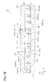
- FIG. 14 is a top view of a specific configuration in a variable-wavelength light source of a second embodiment.
- FIG. 15 is a cross-sectional view taken along line A-A of FIG. 14 .
- FIG. 16 is a cross-sectional view taken along line B-B of FIG. 14 .
- FIG. 17 is a diagram illustrating a basic configuration of a variable-wavelength light source of modified example 1.
- FIG. 18 is a diagram illustrating a first oscillation state in a specific configuration of the variable-wavelength light source of modified example 1.
- FIG. 19 is a diagram illustrating a second oscillation state in the specific configuration of the variable-wavelength light source of modified example 1.
- FIG. 20 is a diagram illustrating a third oscillation state in the specific configuration of the variable-wavelength light source of modified example 1.
- FIG. 21 is a diagram illustrating a basic configuration of a variable-wavelength light source of modified example 2.
- variable-wavelength light source 1 A is a laser oscillation type variable-wavelength light source.
- Emission light Lout emitted from the variable-wavelength light source 1 A has a predetermined wavelength band BL (see FIG. 3 ) and a predetermined wavelength interval ⁇ .
- the variable-wavelength light source 1 A includes a first optical resonator R 1 , a second optical resonator R 2 , a third optical resonator R 3 , and an optical controller C.
- the first wavelength band B 1 forms a part of a wavelength band BL of the emission light Lout (see FIG. 3 ).
- the first optical resonator R 1 includes a first laser medium M 1 , a total reflection mirror (first total reflection mirror) K 1 A, and a half-mirror (first partial reflection mirror) K 2 .
- the first optical resonator R 1 forms a first optical path OP 1 of the first light L 1 .
- the first light L 1 reaching the total reflection mirror K 1 A after the first light L 1 is reflected by the half-mirror K 2 is within a gain band of the first laser medium M 1
- the first light L 1 oscillates between the total reflection mirror K 1 A and the half-mirror K 2 .
- the emission light Lout is emitted from the half-mirror K 2 .
- the first laser medium M 1 emits and amplifies the first light L 1 having the first wavelength band B 1 .
- the gain band of the first laser medium M 1 is equivalent to a first wavelength band B 1 .
- the total reflection mirror K 1 A is arranged on an opposite side of a light-emitting surface M 1 a of the first laser medium M 1 on the first optical path OP 1 .
- the total reflection mirror K 1 A reflects the first light L 1 of the first wavelength band B 1 . Reflectance of the total reflection mirror K 1 A is ideally 100% in the first wavelength band B 1 . Also, the reflectance of the total reflection mirror K 1 A need not necessarily be 100%.
- the total reflection mirror K 1 A is formed integrally with the first laser medium M 1 .
- the total reflection mirror K 1 A may be arranged to be separated from a surface of a side opposite to the light-emitting surface M 1 a of the first laser medium M 1 .
- the variable-wavelength light source 1 A has a Fabry-Perot interference filter as will be described later.
- the variable-wavelength light source 1 A has the half-mirror K 2 arranged on the first optical path OP 1 to return the first light L 1 to the first laser medium M 1 .
- the half-mirror K 2 has lower reflectance than the total reflection mirror K 1 A in a wavelength band including the first wavelength band B 1 .
- the second optical resonator R 2 emits emission light Lout having the second wavelength band B 2 ( ⁇ 2 - 1 ⁇ 2 - 2 : see FIG. 3( a ) ) that differs from the first optical resonator R 1 .
- the second wavelength band B 2 forms a part of a wavelength band BL of the emission light Lout (see FIG. 3 ).
- the second optical resonator R 2 includes a second laser medium M 2 , a total reflection mirror (second total reflection mirror) K 1 B, and a half-mirror (second partial reflection mirror) K 2 .
- the second optical resonator R 2 forms a second optical path OP 2 of the second light L 2 .
- the second light L 2 oscillates between the total reflection mirror K 1 B and the half-mirror K 2 .
- the emission light Lout is emitted from the half-mirror K 2 .
- the second laser medium M 2 emits and amplifies the second light L 2 having the second wavelength band B 2 .
- the gain band of the second laser medium M 2 is equivalent to the second wavelength band B 2 .
- the total reflection mirror K 1 B is arranged on an opposite side of a light-emitting surface M 2 a of the second laser medium M 2 on the second optical path OP 2 .
- the total reflection mirror K 1 B reflects the second light L 2 of the second wavelength band B 2 .
- an optical path length PL from the total reflection mirror K 1 A to the half-mirror K 2 and an optical path length PL from the total reflection mirror K 1 B to the half-mirror K 2 are set to a distance which is an integer multiple or more of a wavelength within a range of a wavelength interval ⁇ .
- the optical path length PL is set to 10 mm or more because oscillation is possible even when the wavelength of light is 0.9999 ⁇ m.
- the first wavelength band B 1 and the second wavelength band B 2 are different from each other.
- the first wavelength band B 1 is a short wavelength side band ( ⁇ 1 - 1 ⁇ 1 - 2 ).
- the second wavelength band B 2 is a long wavelength side band ( ⁇ 2 - 1 ⁇ 2 - 2 ).
- a longest wavelength ( ⁇ 1 - 2 ) of the first wavelength band B 1 is equal to a shortest wavelength ( ⁇ 2 - 1 ) of the second wavelength band B 2 (see FIG. 3( a ) ).
- the longest wavelength ( ⁇ 1 - 2 ) of the first wavelength band B 1 may be longer than the shortest wavelength ( ⁇ 2 - 1 ) of the second wavelength band B 2 (see FIG. 3( b ) ).
- the first wavelength band B 1 and the second wavelength band B 2 may overlap in a partial band.
- the wavelength band BL of the emission light Lout is a band in which the first wavelength band B 1 and the second wavelength band B 2 are integrated.
- This band ( ⁇ 1 - 1 ⁇ 2 - 2 ) is a band from the shortest wavelength ( ⁇ 1 - 1 ) of the first wavelength band B 1 to the longest wavelength ( ⁇ 2 - 2 ) of the second wavelength band B 2 .
- the optical controller C has a first Fabry-Perot interference filter FP 1 (hereinafter referred to as a “first filter FP 1 ”), a second Fabry-Perot interference filter FP 2 (hereinafter referred to as a “second filter FP 2 ”), a first drive mechanism A 1 , a second drive mechanism A 2 , and a drive control unit (control unit) DC.
- the first Fabry-Perot interference filter FP 1 sweeps a wavelength of the emission light Lout.
- the second Fabry-Perot interference filter FP 2 selectively reflects or transmits the first light L 1 of the first laser medium M 1 and the second light L 2 of the second laser medium M 2 and guides the reflected or transmitted light to the first filter FP 1 .
- the first drive mechanism A 1 controls a transmission wavelength ⁇ p 1 of the first filter FP 1 .
- the second drive mechanism A 2 controls a transmission wavelength ⁇ p 2 of the second filter FP 2 .
- the drive control unit DC controls the first drive mechanism A 1 and the second drive mechanism A 2 .
- the first filter FP 1 guides the first light L 1 and the second light L 2 to the half-mirror K 2 and has a function of selectively transmitting and reflecting light of a specific wavelength included in the first light L 1 and the second light L 2 .
- a Fabry-Perot type wavelength selecting filter has a configuration in which two mirrors are arranged in parallel. The mirrors are Bragg mirrors having films of different diffractive indices which are alternately arranged.
- the first filter FP 1 has a pair of first mirrors S 1 a and S 1 b .
- the transmission wavelength ⁇ p 1 of the first filter FP 1 is defined by a first gap G 1 between the first mirror S 1 a and the first mirror S 1 b .
- the first filter FP 1 is arranged at a first position E 1 .
- the first position E 1 is a position between the first laser medium M 1 and the half-mirror K 2 on the first optical path OP 1 and is a position between the second laser medium M 2 and the half-mirror K 2 on the second optical path OP 2 .
- the first filter FP 1 is arranged to be tilted toward the first optical path OP 1 and the second optical path OP 2 so that reflected light is not returned to the first laser medium M 1 and the second laser medium M 2 . It is only necessary to deviate each of an angle formed by the first optical path OP 1 and the first filter FP 1 and an angle formed by the second optical path OP 2 and the first filter FP 1 from 90 degrees.
- the angle for example, is 45 degrees.
- the second filter FP 2 guides the first light L 1 and the second light L 2 to the first filter FP 1 and has a function of selectively transmitting and reflecting light of a specific wavelength included in the first light L 1 and the second light L 2 .
- the second filter FP 2 has a pair of second mirrors S 2 a and S 2 b .
- the transmission wavelength ⁇ p 2 of the second filter FP 2 is defined by a second gap G 2 between the second mirror S 2 a and the second mirror S 2 b .
- the second filter FP 2 is arranged at a second position E 2 .
- the second position E 2 is a position between the first laser medium M 1 and the first filter FP 1 on the first optical path OP 1 and is a position between the second laser medium M 2 and the first filter FP 1 on the second optical path OP 2 .
- the second filter FP 2 is arranged to be tilted in a direction to the second optical path OP 2 so that reflected light is not returned to the second laser medium M 2 . It is only necessary to deviate an angle formed by the second optical path OP 2 and the second filter FP 2 from 90 degrees. The angle, for example, is 45 degrees.
- the lens (first optical component) P 1 is arranged between the first laser medium M 1 and the second filter FP 2 on the first optical path OP 1 .
- the lens (second optical component) P 2 is arranged between the second laser medium M 2 and the second filter FP 2 on the second optical path OP 2 .
- the first drive mechanism A 1 operates the first mirror S 1 a of the first filter FP 1 and the second mirror S 2 a of the second filter FP 2 in conjunction with each other.
- the first drive mechanism A 1 has a frame F 1 and a drive source D 1 .
- the frame F 1 has two mirror connection ends and one drive source connection end.
- the first mirror S 1 a and the second mirror S 2 a are connected to the mirror connection end.
- the drive source D 1 is connected to the drive source connection end.
- the first drive mechanism A 1 operates the first mirror S 1 a and the second mirror S 2 a so that the first gap G 1 of the first filter FP 1 and the second gap G 2 of the second filter FP 2 periodically change.
- first mirror S 1 a and the second mirror S 2 a may be operated in a direction in which the first optical path OP 1 and the second optical path OP 2 are orthogonal or may be operated in a direction along the first optical path OP 1 and the second optical path OP 2 .
- the second drive mechanism A 2 operates the other second mirror S 2 b of the second filter FP 2 .
- the second drive mechanism A 2 has a frame F 2 and a drive source D 2 .
- the second mirror S 2 b is connected to one end side of the frame F 2 .
- the drive source D 2 is connected to the other end side of the frame F 2 .
- the second mirror S 2 b is switched to a first or second state.
- the first state is a state in which the second gap G 2 is different from the first gap G 1 .
- the second state is a state in which the second gap G 2 is equal to the first gap G 1 .
- the drive control unit DC controls the first drive mechanism A 1 and the second drive mechanism A 2 and has a function of inputting control signals to the first drive mechanism A 1 and the second drive mechanism A 2 .
- the drive control unit DC controls the transmission wavelength ⁇ p 1 of the first filter FP 1 by controlling the first drive mechanism A 1 .
- the drive control unit DC controls the transmission wavelength ⁇ p 2 of the second filter FP 2 by controlling the second drive mechanism A 2 .
- specific control of the first filter FP 1 and the second filter FP 2 by the drive control unit DC will be described.
- the first oscillation state is a state in which the first laser medium M 1 performs oscillation.
- the first oscillation state is a state in which light of a wavelength included in the first wavelength band B 1 is transmitted through the first filter FP 1 and reflected (not transmitted) by the second filter FP 2 .
- the first oscillation state is a state in which the gain band of the first laser medium M 1 and the first wavelength band B 1 overlap.
- the transmission wavelength ⁇ p 1 of the first filter FP 1 is different from the transmission wavelength ⁇ p 2 of the second filter FP 2 .
- the drive control unit DC controls the first gap G 1 so that the first filter FP 1 transmits light of the first wavelength band B 1 .
- the drive control unit DC controls the second gap G 2 so that the transmission wavelength ⁇ p 2 of the second filter FP 2 is different from the transmission wavelength ⁇ p 1 of the first filter FP 1 . Specifically, the drive control unit DC controls the position of the second mirror S 2 b.
- the first optical resonator R 1 is formed of the first laser medium M 1 , the total reflection mirror K 1 A, and the half-mirror K 2 .
- the transmission wavelength ⁇ p 1 of the first filter FP 1 needs to be included in the gain band of the first laser medium M 1 .
- the gain band of the first laser medium M 1 is the first wavelength band B 1 ( ⁇ 1 - 1 ⁇ 1 - 2 ).
- the transmission wavelength ⁇ p 2 of the second filter FP 2 is set to a different value from the transmission wavelength ⁇ p 1 .
- the transmission wavelength band of the first filter FP 1 is different from that of the second filter FP 2 .
- light of the transmission wavelength ⁇ p 1 is necessarily reflected by the second filter FP 2 .
- the light of the transmission wavelength ⁇ p 1 included in the first light L 1 is reflected by the second filter FP 2 and transmitted by the first filter FP 1 and reaches the half-mirror K 2 .
- the light of the transmission wavelength ⁇ p 1 is reflected by the half-mirror K 2 and reaches the total reflection mirror K 1 A along a reverse path. Therefore, the first optical resonator R 1 is formed between the total reflection mirror K 1 A and the half-mirror K 2 .
- the first laser medium M 1 performs oscillation and emission light Lout of the transmission wavelength ⁇ p 1 is emitted. Also, in the first oscillation state, the second light L 2 of the second laser medium M 2 is partially or totally reflected by the second filter FP 2 .
- the second oscillation state is a state in which the second laser medium M 2 performs oscillation.
- the second oscillation state is a state in which light of the wavelength included in the second wavelength band B 2 is transmitted through the first filter FP 1 and the second filter FP 2 .
- the second oscillation state is a state in which the gain band of the second laser medium M 2 and the second wavelength band B 2 overlap.
- the transmission wavelength ⁇ p 2 of the second filter FP 2 is equal to the transmission wavelength ⁇ p 1 of the first filter FP 1 .
- the drive control unit DC controls the first gap G 1 so that the first filter FP 1 transmits light of the wavelength included in the second wavelength band B 2 .
- the drive control unit DC controls the second gap G 2 so that the transmission wavelength ⁇ p 2 of the second filter FP 2 is equal to the transmission wavelength ⁇ p 1 of the first filter FP 1 . Specifically, the drive control unit DC controls the position of the second mirror S 2 b.
- the second optical resonator R 2 is formed of the second laser medium M 2 , the total reflection mirror K 1 B, and the half-mirror K 2 .
- the transmission wavelength ⁇ p 1 of the first filter FP 1 needs to be included in the gain band of the second laser medium M 2 .
- the gain band is the second wavelength band B 2 ( ⁇ 2 - 1 ⁇ 2 - 2 ).
- the transmission wavelength ⁇ p 2 of the second filter FP 2 is set to a value equal to the transmission wavelength ⁇ p 1 . That is, the transmission wavelength band of the first filter FP 1 and the transmission wavelength band of the second filter FP 2 are equal to each other.
- the second light L 2 of the transmission wavelength ⁇ p 1 is transmitted through the second filter FP 2 and the first filter FP 1 . Accordingly, the light of the transmission wavelength ⁇ p 1 included in the second light L 2 is transmitted through the second filter FP 2 and transmitted through the first filter FP 1 and reaches the half-mirror K 2 . The light of the transmission wavelength ⁇ p 1 is reflected by the half-mirror K 2 and reaches the total reflection mirror K 1 B along a reverse path. Therefore, the second optical resonator R 2 is formed between the total reflection mirror K 1 B and the half-mirror K 2 . The second laser medium M 2 performs oscillation and emission light Lout of the transmission wavelength ⁇ p 1 is emitted.
- the first drive mechanism A 1 and the second drive mechanism A 2 are operated in cooperation with each other so that the second gap G 2 of the second filter FP 2 is equal to the first gap of the first filter FP 1 .
- the first light L 1 of the first laser medium M 1 is totally reflected by the first filter FP 1 after a part or all of the light of the second wavelength band B 2 is reflected by the second filter FP 2 .
- a first non-oscillation state and a second non-oscillation state are also obtained through a combination of the first wavelength band B 1 of the first filter FP 1 and the second wavelength band B 2 of the second filter FP 2 .
- the first non-oscillation state is a state in which the first filter FP 1 transmits the light of the wavelength included in the second wavelength band B 2 and the second filter FP 2 reflects the light of the wavelength included in the second wavelength band B 2 .
- the first non-oscillation state is a state in which the gain band of the first laser medium M 1 does not overlap the second wavelength band B 2 .
- the second non-oscillation state is a state in which the first filter FP 1 transmits light of the wavelength included in the first wavelength band B 1 and the second filter FP 2 transmits the light of the wavelength included in the first wavelength band B 1 .
- the second non-oscillation state is a state in which the gain band of the second laser medium M 2 and the first wavelength band B 1 do not overlap. Accordingly, in the second non-oscillation state, the second laser medium M 2 does not perform oscillation.
- the drive control unit DC does not control the transmission wavelength ⁇ p 1 of the first filter FP 1 and the transmission wavelength ⁇ p 2 of the second filter FP 2 in these states.
- FIG. 6( a ) illustrates temporal changes in control signals input from the drive control unit DC to the first drive mechanism A 1 and the second drive mechanism A 2 .
- the vertical axis represents a voltage of a control signal.
- the horizontal axis represents time.
- a graph GP 1 (solid line) indicates the control signal input to the first drive mechanism A 1 .
- a graph GP 2 (broken line) indicates the control signal input to the second drive mechanism A 2 .
- FIG. 6( b ) illustrates temporal changes in the transmission wavelength ⁇ p 1 of the first filter FP 1 and the transmission wavelength ⁇ p 2 of the second filter FP 2 .
- the vertical axis represents a transmission wavelength.
- the horizontal axis represents time.
- a graph GP 3 (solid line) represents the transmission wavelength ⁇ p 1 of the first filter FP 1 .
- a graph GP 4 (broken line) represents the transmission wavelength ⁇ p 2 of the second filter FP 2 .
- the amplitude (graph GP 3 ) of the transmission wavelength ⁇ p 1 of the first filter FP 1 includes the first wavelength band B 1 of the first light L 1 of the first laser medium M 1 and the second wavelength band B 2 of the second light L 2 of the second laser medium M 2 .
- This wavelength band corresponds to the wavelength band BL of the emission light Lout emitted from the variable-wavelength light source 1 A (see FIG. 3 ).
- the transmission wavelength ⁇ p 1 of the first filter FP 1 is controlled by the control signal (graph GP 1 ) input to the first drive mechanism A 1 .
- the control signal input to the first drive mechanism A 1 corresponds to a wavelength sweeping speed of the emission light Lout emitted from the variable-wavelength light source 1 A.
- the operation control of the first drive mechanism A 1 may be an operation at a relatively low speed according to a voltage of the control signal.
- the operation control of the first drive mechanism A 1 may be a relatively high speed resonance operation to be implemented by applying a control signal of a frequency matching the resonance frequency of the first drive mechanism A 1 .
- the drive control unit DC inputs sine-wave-shaped control signals (V 0 ⁇ V 1 ) to the first drive mechanism A 1 in a period Z 1 (t 0 ⁇ t 2 ).
- the drive control unit DC inputs a control signal (V 2 ) to the second drive mechanism A 2 in a period Z 1 a (t 0 ⁇ t 1 ) included in the period Z 1 (t 0 ⁇ t 2 ) (see FIG. 6( a ) ).
- the one first mirror S 1 a is separated from the other first mirror S 1 b which is fixed and the transmission wavelength ⁇ p 1 of the first filter FP 1 changes from ⁇ 1 - 1 to ⁇ 1 - 2 . That is, the transmission wavelength ⁇ p 1 of the first filter FP 1 gradually increases.
- the other second mirror S 2 b moves to a position corresponding to the control signal (V 2 ) and is in the first state.
- the one second mirror S 2 a reciprocates with respect to the other second mirror S 2 b in the first state.
- the operation of the second mirror S 2 a is synchronized with the operation of the first mirror S 1 a of the first filter FP 1 .
- the second gap G 2 of the second filter FP 2 is not equal to the first gap G 1 of the first filter FP 1 . Accordingly, the transmission wavelength ⁇ p 2 of the second filter FP 2 changes to have a value different from the transmission wavelength ⁇ p 1 of the first filter FP 1 . That is, as illustrated in the period Z 1 of FIG. 6( b ) , the graph GP 3 and the graph GP 4 do not overlap. Therefore, in the period Z 1 , the first oscillation state is implemented.
- the drive control unit DC inputs sine-wave-shaped control signals (V 1 ⁇ V 3 ⁇ V 1 ) to the first drive mechanism A 1 in a period Z 2 (t 2 ⁇ t 3 ).
- the drive control unit DC inputs the control signal (V 1 ) to the second drive mechanism A 2 .
- the other second mirror S 2 b moves to a position corresponding to the control signal (V 1 ) and is in the second state.
- the one second mirror S 2 a reciprocates with respect to the other second mirror S 2 b in the second state.
- the operation of the second mirror S 2 a is in synchronization with the operation of the first mirror S 1 a of the first filter FP 1 .
- the second gap G 2 of the second filter FP 2 is equal to the first gap G 1 of the first filter FP 1 . Accordingly, the transmission wavelength ⁇ p 2 of the second filter FP 2 changes to have a value equal to the transmission wavelength ⁇ p 1 of the first filter FP 1 . That is, as illustrated in the period Z 2 of FIG. 6( b ) , the graph GP 3 and the graph GP 4 overlap. Therefore, in the period Z 2 , the second oscillation state is implemented.
- the drive control unit DC inputs sine-wave-shaped control signals (V 1 ⁇ V 0 ⁇ V 1 ) to the first drive mechanism A 1 in a period Z 3 .
- the drive control unit DC inputs the control signal (V 2 ) to the second drive mechanism A 2 . According to these control signals, as in the period Z 1 , the first oscillation state is implemented.
- the emission light Lout is emitted from the variable-wavelength light source 1 A by alternately iterating the period 72 in the first oscillation state and the period Z 3 in the second oscillation state.
- the drive control unit DC sets the control signal to be input to the second drive mechanism A 2 as a constant voltage control signal (V 2 ) in a period Z 1 a (t 0 ⁇ t 1 ) included in the period Z 1 and sets the control signal to be input to the second drive mechanism A 2 as control signals (V 2 ⁇ V 1 ) for gradually changing the magnitude of the voltage in the next period Z 1 b (t 1 ⁇ t 2 ).
- the transmission wavelength ⁇ p 2 of the second filter FP 2 is completely equal to the transmission wavelength ⁇ p 1 of the first filter FP 1 .
- the control signal to be input to the second drive mechanism A 2 is a signal other than V 1 .
- the transmission wavelength ⁇ p 2 of the second filter FP 2 needs to be equal to the transmission wavelength ⁇ p 1 of the first filter FP 1 .
- the first laser medium M 1 continuously performs oscillation at the transmission wavelength ⁇ p 1 of the first filter FP 1 even in the period Z 1 b (t 1 ⁇ t 2 ) and a period Z 3 a (t 3 ⁇ t 4 ). Accordingly, even when a predetermined time is required until the movement of the second drive mechanism A 2 is completed after the control signal is input, the first oscillation state is maintained.
- the second drive mechanism A 2 does not instantaneously stop and ringing or the like may occur even when the control signal is fixed to the constant voltage (V 1 or V 2 ) according to a resonance frequency component.
- the movement distance of the other second mirror S 2 b corresponds to a wavelength (for example, 1 nm) which is several times a filter half-value width of the Fabry-Perot interference filter. Accordingly, because the amplitude (voltage width) of the control signal is small and may be smoothly operated, it is possible to smoothly perform the oscillation switching of the first laser medium M 1 and the second laser medium M 2 without loss.
- the first gap G 1 of the first filter FP 1 changes in proportion to an operation position of the first drive mechanism A 1 and the transmission wavelength ⁇ p 1 of the first filter FP 1 also linearly changes with respect to the first gap G 1 .
- the operation position of the actuator is not linear with respect to the drive voltage.
- the operation position is in proportion to a square of the drive voltage.
- a relation between the operation position and the drive voltage is more complex.
- the light intensity of the emitted light Lout from the variable-wavelength light source 1 A may be discontinuous at the time of switching from the first laser medium M 1 to the second laser medium M 2 or the time of switching from the second laser medium M 2 to the first laser medium M 1 .
- the emitted light Lout is not emitted outside the half value width of the transmission wavelength ⁇ p 1 of the first filter FP 1 .
- the emission light Lout having the wavelength within the half-value width is emitted.
- the gain is different between the first laser medium M 1 and the second laser medium M 2 , the light intensity of the emission light Lout may rapidly change.
- the second laser medium M 2 does not perform oscillation despite the fact that current injection is sustained. Therefore, in the first oscillation state, energy is stored within the second laser medium M 2 . Immediately after the oscillation from the first laser medium M 1 to the second laser medium M 2 is switched, that is, at the time of initial oscillation of the second laser medium M 2 , the stored energy is rapidly released and a high pulse of a peak value is generated. This phenomenon is the same as that of the principle of a so-called Q switch. When this pulse is generated, a saturation phenomenon of a detector side occurs in a measuring instrument using the variable-wavelength light source 1 A and the measurement may be impeded.
- the variable-wavelength light source 1 A includes a third optical resonator R 3 .
- the third optical resonator R 3 prevents a pulse for causing the discontinuity of the light intensity from occurring.
- the third optical resonator R 3 has two forms.
- a third optical resonator R 3 a which is the first form has a first laser medium M 1 , a total reflection mirror K 1 A, a half-mirror K 3 , and a third Fabry-Perot interference filter FP 3 (hereinafter referred to as a “third filter FP 3 ”).
- a third optical resonator R 3 b which is the second form has a second laser medium M 2 , a total reflection mirror K 1 B, a half-mirror K 3 , and a third filter FP 3 .
- the third filter FP 3 is a wavelength selecting filter having a similar configuration to the first filter FP 1 .
- the third filter FP 3 is arranged on a first optical path OP 1 in which light is transmitted through the second filter FP 2 and a second optical path OP 2 in which light is reflected by the second filter FP 2 .
- the third filter FP 3 is arranged so that the second filter FP 2 is positioned between the second laser medium M 2 and the third filter FP 3 .
- the third filter FP 3 has a pair of third mirrors S 3 a and S 3 b .
- One third mirror S 3 a of the third filter FP 3 is connected to the first drive mechanism A 1 . Therefore, the third mirror S 3 a operates in conjunction with the first mirror S 1 a and the second mirror S 2 a .
- the other third mirror S 3 b is fixed at a fixed position.
- another drive mechanism may be attached to the other first mirror S 1 b of the first filter FP 1 or the other third mirror S 3 b of the third filter FP 3 .
- An initial position of the first mirror S 1 b or the third mirror S 3 b is adjusted so that the third gap G 3 of the third filter FP 3 is equal to the first gap G 1 of the first filter FP 1 .
- the half-mirror K 3 is arranged on the first optical path OP 1 and the second optical path OP 2 .
- the third filter FP 3 is arranged between the second filter FP 2 and the half-mirror K 3 .
- the half-mirror K 3 is a total reflection mirror or a half-mirror. It is only necessary for the half-mirror K 3 to have reflectance sufficient for laser oscillation. It is possible to use a mirror using a material having a high refractive index such as silicon in the half-mirror K 3 . In the case of the mirror using silicon as the material having the high refractive index, it is suitable for the half-mirror K 3 because it is possible to perform reflection of about 30% in Fresnel reflection of an end surface and wavelength dependency is substantially absent.
- a pulse suppression operation by the third optical resonator R 3 will be described. As illustrated in FIG. 3( b ) , when the pulse is suppressed using the third optical resonator R 3 , the first wavelength band B 1 of the first laser medium M 1 and the second wavelength band B 2 of the second laser medium M 2 partially overlap. This is to smoothly perform wavelength switching.
- This redundant band BD ( ⁇ 2 - 1 ⁇ 1 - 2 ) is in a state in which a gain is obtained in any of the first laser medium M 1 and the second laser medium M 2 (that is, a state in which oscillation is possible).
- the second light L 2 does not include light of the wavelength of ⁇ 1 - 1 ⁇ 2 - 1 , all the second light L 2 is reflected.
- the transmission wavelength ⁇ p 1 of the first filter FP 1 changes to a wavelength (a period W 2 of FIG. 3( b ) ) within the redundant band BD
- the transmission wavelength ⁇ p 3 of the third filter FP 3 also becomes a wavelength (the period W 2 of FIG. 3( b ) ) within the redundant band BD.
- the light of the transmission wavelength ⁇ p 1 included in the second light L 2 is transmitted through the third filter FP 3 and reflected by the half-mirror K 3 , and reaches the total reflection mirror K 1 B along a reverse path.
- the first light L 1 does not include light of the wavelength of ⁇ 1 - 2 ⁇ 2 - 2 , all the first light L 1 is reflected.
- the transmission wavelength ⁇ p 1 of the first filter FP 1 changes to a wavelength within the redundant band BD (the period W 2 of FIG. 3( b ) )
- light of the transmission wavelength ⁇ p 1 in the first light L 1 is reflected by the half-mirror K 3 after being transmitted through the second filter FP 2 and the third filter FP 3 and reaches the total reflection mirror K 1 A along a reverse path. Therefore, an optical path is formed between the total reflection mirror K 1 A and the half-mirror K 3 .
- the transmission wavelength ⁇ p 1 is within a gain band of the first laser medium M 1 , energy stored in the first laser medium M 1 in which the third optical resonator R 3 a is formed is released.
- oscillation starts even in the laser medium of a non-oscillation side.
- the oscillating light is not extracted to an emission side even when a high pulse of a peak value oscillates in oscillation in the third optical resonator R 3 a and the third optical resonator R 3 b.
- variable-wavelength light source 1 A an operation and effect of the variable-wavelength light source 1 A will be described.
- the laser medium for the variable-wavelength light source is manufactured through crystal growth in which the number of levels within the crystal increases due to an increase in impurities or the like.
- the number of crystal defects increases according to this crystal growth, it is difficult to increase an oscillation width without limitation. Therefore, there is a limitation on a method of extending a variable-wavelength width in a single laser medium.
- variable-wavelength width determines the resolution in optical coherence tomography (OCT). Therefore, in the OCT, the resolution is higher when the variable-wavelength band is wider.
- OCT optical coherence tomography
- a plurality of light sources having different center wavelengths are used, light emitted from the plurality of light sources is multiplexed according to a method of switching or the like of an optical coupler or a shutter. For example, when the light is emitted from one single-mode optical filter as in the OCT or the like, light is multiplexed by a fiber coupler or the like. In this case, a power loss of 50% occurs in principle.
- variable-wavelength light source When the variable-wavelength light source is configured to be applied to various measurement apparatuses as described above, it is necessary to extend a variable-wavelength range in any method and variable-wavelength light sources capable of inexpensively and efficiently extending the variable-wavelength range are being investigated.
- the variable-wavelength light source 1 A includes the first laser medium M 1 and the second laser medium M 2 configured to amplify light having different wavelength bands.
- the wavelength band BL of the emission light Lout of the variable-wavelength light source 1 A is a combination of the first wavelength band B 1 of the first light L 1 amplified by the first laser medium M 1 and the second wavelength band B 2 of the second light L 2 amplified by the second laser medium M 2 . Accordingly, the first laser medium M 1 and the second laser medium M 2 configured to amplify the light having the different wavelength bands are provided, so that it is possible to extend the wavelength band BL of the emission light Lout.
- the first drive mechanism A 1 operates one first mirror S 1 a and one second mirror S 2 a in conjunction with each other and the second drive mechanism A 2 drives the other second mirror S 2 b .
- the transmission wavelength ⁇ p 1 of the first filter FP 1 and the transmission wavelength ⁇ p 2 of the second filter FP 2 can be identical or different.
- the first optical resonator R 1 configured to cause the first light L 1 of the first laser medium M 1 to optically resonate
- the second optical resonator R 2 configured to cause the second light L 2 of the second laser medium M 2 to optically resonate are selectively configured.
- variable-wavelength light source 1 A can stabilize optical characteristics of the emission light Lout and extend the wavelength band BL of the emission light Lout.
- the variable-wavelength light source 1 A can periodically change the wavelength band BL of the emission light Lout of the variable-wavelength light source 1 A because the transmission wavelength ⁇ p 1 of the first filter FP 1 and the transmission wavelength ⁇ p 2 of the second filter FP 2 periodically change.
- the first mirror S 1 a and the second mirror S 2 a of the variable-wavelength light source 1 A operate at a resonance frequency of the first drive mechanism A 1 . Therefore, energy necessary to drive the first mirror S 1 a and the second mirror S 2 a at predetermined amplitude is suppressed and it is possible to drive the first mirror S 1 a and the second mirror S 2 a with high efficiency at a high frequency.
- the drive control unit DC of the variable-wavelength light source 1 A Through control to be performed by the drive control unit DC of the variable-wavelength light source 1 A, it is possible to cause the transmission wavelength ⁇ p 2 of the second filter FP 2 to be different from the transmission wavelength ⁇ p 1 of the first filter FP 1 in a first state in which the second gap G 2 is different from the first gap G 1 . On the other hand, in a second state in which the second gap G 2 is equal to the first gap G 1 , it is possible to cause the transmission wavelength ⁇ p 2 of the second filter FP 2 to be equal to the transmission wavelength ⁇ p 1 of the first filter FP 1 .
- the variable-wavelength light source 1 A includes a lens P 1 and a lens P 2 . Therefore, it is possible to efficiently use the first light L 1 amplified by the first laser medium M 1 and the second light L 2 amplified by the second laser medium M 2 .
- variable-wavelength light source 1 A can be reduced more than that of a light source based on coupling of an optical coupler or the like and a highly efficient operation can be implemented at a high speed.
- the variable-wavelength light source 1 A can cause the first laser medium M 1 and the second laser medium M 2 to be constantly in a current application state. Therefore, it is possible to operate the first laser medium M 1 and the second laser medium M 2 in a thermally stable operation state. Further, the emission light Lout is emitted from the half-mirror K 2 on the same optical path. Therefore, the optical design of a subsequent stage to be coupled to the optical fiber is facilitated.
- the variable-wavelength light source 1 A is a laser oscillation type light source for causing the first optical resonator R 1 to oscillate the first light L 1 and causing the second optical resonator R 2 to oscillate the second light L 2 .
- an operation and effect of the variable-wavelength light source 1 A will be further described with a comparison between a spectroscopic apparatus having the variable-wavelength light source 1 A which is a laser oscillation type and a spectroscopic apparatus having a white light source such as a halogen lamp.
- the spectroscopic apparatus having the white light source In the spectroscopic apparatus having the white light source, light emitted from the white light source is radiated to a sample and reflected light or transmitted light is guided to a spectroscope.
- An optical spot size is limited using a slit for improving the resolution in an optical incident port of the spectroscope. Through the limit of the spot size, light including a signal component is lost.
- Light passing through the slit is dispersed by a diffraction grating and detected as a wavelength-specific signal in each pixel of an image sensor. This signal is read by the signal read circuit. The read signal is subjected to data processing by a personal computer or the like and displayed as a spectrum image.
- the spectroscope or the image sensor is unnecessary in the spectroscopic apparatus having the variable-wavelength light source 1 A, it is possible to configure an inexpensive detection unit in a small size.
- spectrum information is obtained, the wavelength of the emission light Lout of the variable-wavelength light source 1 A is scanned in synchronization with a control signal output from the personal computer or the like and wavelength-specific data is acquired.
- a wavelength scanner is necessary according to the spectroscopic apparatus having the variable-wavelength light source 1 A, but substantially the same time even in the reading of pixel information in the image sensor of the spectroscope is required, there is no superiority related to a measurement time.
- variable-wavelength light source 1 A can adopt a method of radiating light matching a sample according to the purpose of use.
- variable-wavelength light source 1 A can easily implement a wavelength resolution of 1 nm or less basically because oscillation is laser oscillation.
- the second light L 2 of the second laser medium M 2 may be directly incident on the second filter FP 2 , but may be arranged to be emitted in the same direction as the first light L 1 of the first laser medium M 1 and arranged to be guided to the second filter FP 2 using an optical component such as a total reflection mirror.
- variable-wavelength light source 1 A The specific configuration of the variable-wavelength light source 1 A will be described.
- surface micromachining which is MEMS technology is used. Through the surface micromachining, it is possible to manufacture the variable-wavelength light source 1 A in a small size and at a low cost.
- the variable-wavelength light source 1 B has an MEMS structure 3 .
- This MEMS structure 3 is obtained by forming the first filter FP 1 , the second filter FP 2 , the third filter FP 3 , the first drive mechanism A 1 , and the second drive mechanism A 2 in a silicon substrate (semiconductor substrate) 2 .
- a silicon substrate semiconductor substrate
- a total reflection mirror 4 formed of a metal film is formed in a surface 2 a of the silicon substrate 2 .
- a substrate electrode 12 is formed on the silicon substrate 2 .
- a laser diode LD 1 On the MEMS structure 3 , a laser diode LD 1 , a laser diode LD 2 , a lens P 1 , a lens P 2 , a total reflection mirror 6 , a half-mirror K 2 , a half-mirror K 3 , and an output lens Pu are arranged.
- the MEMS structure 3 includes a lower mirror layer BM and an upper mirror layer TM.
- the lower mirror layer BM is arranged to be separated upward from a surface 2 b of the silicon substrate 2 .
- the upper mirror layer TM is arranged to be separated upward from the lower mirror layer BM.
- the lower mirror layer BM and the upper mirror layer TM have a Bragg mirror structure for a Fabry-Perot type wavelength selecting filter.
- a plurality of support portions 7 for supporting the lower mirror layer BM are arranged between the silicon substrate 2 and the lower mirror layer BM.
- a plurality of air gaps AG 1 are formed between the plurality of support portions 7 .
- a support portion 8 for supporting the upper mirror layer TM is arranged between the lower mirror layer BM and the upper mirror layer TM.
- Air gaps AG 2 are formed between a plurality of support portions 8 .
- a configuration in which the upper mirror layer TM is formed on the lower mirror layer BM is a structure which forms a Fabry-Perot interference filter.
- the lower mirror layer BM and the upper mirror layer TM are divided into a plurality of Fabry-Perot interference filters by the support portions 7 . Therefore, in the MEMS structure 3 , a plurality of Fabry-Perot interference filters are arranged in a direction along the surface 2 b of the silicon substrate 2 .
- the lower mirror layer BM is formed on a silicon oxide film T 1 of the silicon substrate 2 .
- a thickness K 1 of the lower mirror layer BM is set to (1 ⁇ 4 ⁇ c/n) with respect to a center wavelength ⁇ c of the wavelength band BL of the emission light Lout.
- n is a refractive index of each layer.
- the lower mirror layer BM has a structure in which polysilicon films T 2 of four layers and silicon nitride films T 3 of three layers are alternately stacked.
- a lower electrode 9 is electrically connected to a polysilicon film T 2 a which forms the surface of the lower mirror layer BM.
- the lower mirror layer BM has an etching hole 12 a for forming the air gap AG 1 .
- the height of the air gap AG 1 below the second filter FP 2 is set to (1 ⁇ 4 ⁇ c) with respect to the center wavelength ⁇ c of the emission light Lout to form a part of the lower mirror layer BM.
- the lower electrode 9 is provided in a left center of the polysilicon film T 2 a which forms the surface of the lower mirror layer BM.
- One end of a wiring pattern 11 a is connected to the lower electrode 9 .
- the other end of the wiring pattern 11 a is connected to a circular movable portion 11 .
- the movable portion 11 is surrounded by an insulating pattern 11 b for electrically insulating the movable portion 11 from a surrounding region 13 .
- the movable portion 11 is electrically insulated from the surrounding region 13 .
- the movable portion 11 is physically integrated with the surrounding region 13 .
- the upper mirror layer TM is formed on the lower mirror layer BM via the silicon oxide film T 4 formed on the polysilicon film T 2 a .
- the upper mirror layer TM has a similar structure to the lower mirror layer BM.
- An upper electrode 14 is electrically connected to the polysilicon film T 2 b which forms the surface of the upper mirror layer TM.
- An etching hole 12 b for forming the air gap AG 2 is formed in the upper mirror layer TM.
- the upper mirror layer TM has a circular movable portion 17 .
- the movable portion 17 is electrically insulated from a surrounding region 16 in which the upper electrode 14 is electrically connected.
- the movable portion 17 is surrounded by an insulating pattern 18 for electrically insulating the movable portion 17 from the surrounding region 16 .
- the movable portion 17 is electrically insulated from the surrounding region 16 , so that, when a voltage is applied to the lower electrode 9 , it is possible to prevent the movable portion 17 of the upper mirror layer TM from moving due to pulling by an electrostatic force due to its potential difference.
- the movable portion 17 is electrically insulated from the surrounding region 16 .
- the movable portion 17 is physically integrated with the surrounding region 16 .
- FIG. 11( a ) A specific example of reflection characteristics of the upper mirror layer TM and the lower mirror layer BM will be described with reference to FIG. 11( a ) .
- the horizontal axis of FIG. 11( a ) represents a wavelength.
- the vertical axis represents reflectance.
- a graph GP 5 (solid line) represents reflection characteristics of the upper mirror layer TM.
- a graph GP 6 (broken line) represents reflection characteristics of the lower mirror layer BM.
- the upper mirror layer TM and the lower mirror layer MB have a reflectance of 98% or more in the wavelength band BL (for example, 1.2 ⁇ m ⁇ 1.4 ⁇ m) of the emission light Lout.
- the upper mirror layer TM and the lower mirror layer BM it is possible to configure a Fabry-Perot interference filter for transmitting light of 98% or more in a variable-wavelength range of ⁇ 100 nm having a center wavelength of 1.3 ⁇ m.
- the first filter FP 1 and the second filter FP 2 formed by the lower mirror layer BM and the upper mirror layer TM as illustrated in FIG. 8 will be described.
- the first filter FP 1 is formed of the surrounding region 13 of the lower mirror layer BM and the upper mirror layer TM.
- the MEMS structure 3 has three first filters FP 1 a , FP 1 b , and FP 1 c which are equivalent to one another.
- the second filter FP 2 is formed of the movable portion 11 of the lower mirror layer BM and the upper mirror layer TM.
- the transmission wavelength ⁇ p 1 of the first filter FP 1 and the transmission wavelength ⁇ p 2 of the second filter FP 2 are determined by the air gap AG 2 .
- the air gap AG 2 changes when the upper mirror layer TM moves toward or away from the lower mirror layer BM.
- the first filter FP 1 , the second filter FP 2 , and the third filter FP 3 are assumed to be formed of the upper mirror layer TM and the lower mirror layer BM having reflection characteristics illustrated in FIG. 11( a ) .
- the horizontal axis of FIG. 11( b ) represents a transmission wavelength.
- the vertical axis represents transmittance.
- a graph GP 7 represents wavelength characteristics when the air gap AG 2 is 1.76 ⁇ m.
- a graph GP 8 represents wavelength characteristics when the air gap AG 2 is 1.9 ⁇ m.
- a graph GP 9 represents wavelength characteristics when the air gap AG 2 is 2.0 ⁇ m.
- a graph GP 10 represents wavelength characteristics when the air gap AG 2 is 2.13 ⁇ m.
- a transmittance of 98% or more is obtained at a peak point at a transmission wavelength in any of the air gaps AG 2 .
- the upper mirror layer TM is driven by an electrostatic force to be generated between the upper mirror layer TM and the lower mirror layer BM.
- a control signal indicated by the graph GP 1 of FIG. 6( a ) is input to the upper electrode 14
- a control signal indicated by the graph GP 2 of FIG. 6( b ) is input to the lower electrode 9
- a control signal of a reference potential (GND) is applied to the substrate electrode 12 .
- a predetermined potential difference occurs between the upper mirror layer TM and the lower mirror layer BM and an electrostatic force corresponding to this potential difference is generated by the principle of a parallel plate capacitor.
- the transmission wavelength ⁇ p 1 of the first filter FP 1 , the transmission wavelength ⁇ p 2 of the second filter FP 2 , and the transmission wavelength ⁇ p 3 of the third filter FP 3 periodically change.
- the upper mirror layer TM corresponds to the first mirror S 1 a , the second mirror S 2 a , and the third mirror S 3 a .
- the upper mirror layer TM corresponds to a frame F 1 and a drive source D 1 of the first drive mechanism A 1 for causing each mirror to operate.
- the lower mirror layer BM corresponds to the second mirror S 2 b .
- the lower mirror layer BM corresponds to a frame F 2 and a drive source D 2 of the second drive mechanism A 2 for causing the second mirror S 2 b to operate.
- this state is a first state in which the second gap G 2 of the second filter FP 2 is different from the first gap G 1 of the first filter FP 1 . That is, when the voltage of the control signal input to the lower electrode 9 is different from the voltage of the control signal input to the substrate electrode 12 , the second mirror S 2 b is in the first state.
- the transmission wavelength ⁇ p 2 of the second filter FP 2 is equal to the transmission wavelengths ⁇ p 1 of the first filters FP 1 a , FP 1 b , and FP 1 c and the transmission wavelength ⁇ p 3 of the third filter FP 3 . That is, when the voltage of the control signal input to the lower electrode 9 is equal to the voltage of the control signal input to the substrate electrode 12 , the second mirror S 2 b is in the second state.
- the laser diode LD 1 is obtained by integrating the first laser medium M 1 and the total reflection mirror K 1 A.
- a surface light-emitting element vertical cavity surface emitting laser (VCSEL)
- VCSEL vertical cavity surface emitting laser
- the laser diode LD 1 is arranged on the MEMS structure 3 so that an emission direction of the first light L 1 is tilted toward the first filter FP 1 a .
- the lens P 1 is arranged on the first optical path OP 1 between the laser diode LD 1 and the first filter FP 1 a.
- the laser diode LD 2 is obtained by integrating the second laser medium M 2 and the total reflection mirror K 1 B.
- the laser diode LD 2 is arranged on the MEMS structure 3 so that an emission direction of the second light L 2 is tilted toward the second filter FP 2 .
- An angle formed by the emission direction of the second light L 2 of the laser diode LD 2 and the surface of the silicon substrate 2 is the same as an angle formed by the emission direction of the first light L 1 of the laser diode LD 1 and the surface 3 a of the MEMS structure 3 .
- the lens P 2 is arranged on the second optical path OP 2 between the laser diode LD 2 and the second filter FP 2 .
- the half-mirror K 2 is for the first optical resonator R 1 or the second optical resonator R 2 .
- the half-mirror K 2 is arranged in a traveling direction of light transmitted through the first filter FP 1 b on the MEMS structure 3 .
- the first light L 1 or the second light L 2 transmitted through the first filter FP 1 b is incident on the half-mirror K 2 .
- the output lens Pu for collimating the light transmitted through the half-mirror K 2 is arranged in the traveling direction of the light transmitted through the half-mirror K 2 .
- the half-mirror K 3 is for the third optical resonator R 3 .
- the half-mirror K 3 is arranged in the traveling direction of the light transmitted through the third filter FP 3 on the MEMS structure 3 .
- the first light L 1 or the second light L 2 transmitted through the third filter FP 3 is incident on the half-mirror K 3 .
- Tilt angles of the half-mirror K 2 and the half-mirror K 3 formed with the surface 3 a of the MEMS structure 3 become ⁇ 90 degrees with respect to tilt angles of a light emission direction of the laser diode LD 1 and the laser diode LD 2 formed with the surface 3 a of the MEMS structure 3 .
- the tilt angles of the laser diode LD 1 and the laser diode LD 2 and the tilt angles of the half-mirror K 2 and the half-mirror K 3 are not essential.
- Each arrangement angle can be set to a desired angle other than 0 degrees (when light is incident to be perpendicular to the first filter FP 1 and the second filter FP 2 ).
- angular dependence of transmission wavelength characteristics of the first filter FP 1 and the second filter FP 2 may increase when the tilt angle increases. Therefore, it is preferable that the tilt angle be 45 degrees or less.
- the laser diode LD 1 , the first filter FP 1 a , and the laser diode LD 2 are arranged so that the first light L 1 of the laser diode LD 1 is not incident on the laser diode LD 2 through reflection by the first filter FP 1 a.
- the laser diode LD 1 , the first filter FP 1 a , and the total reflection mirror 6 are arranged so that the first light L 1 of the laser diode LD 1 is not incident on the total reflection mirror 6 through reflection by the first filter FP 1 a .
- the first light L 1 is reflected by the first filter FP 1 a , so that it is possible to prevent an unintended optical resonator from being formed.
- the half-mirror K 2 and the half-mirror K 3 are arranged to be separated from each other.
- the second light L 2 of the laser diode LD 2 reflected by the second filter FP 2 is reflected by the total reflection mirror 6 and the first filter FP 1 c and travels between the half-mirror K 2 and the half-mirror K 3 . Therefore, the second light L 2 reflected by the first filter FP 1 c is incident on the laser diode LD 2 along a reverse path, so that it is possible to prevent an unintended optical resonator from being formed.
- the total reflection mirror 6 is arranged between the laser diode LD 2 and the half-mirror K 2 so that the total reflection mirror 6 is parallel to the surface 3 a .
- the first light L 1 transmitted through the second filter FP 2 or the second light L 2 reflected by the second filter FP 2 is incident on the total reflection mirror 6 .
- the total reflection mirror 6 reflects the first light L 1 and the second light L 2 to the first filter FP 1 c.
- the total reflection mirror 4 is made of a metal film and is formed in the rear surface 2 a of the silicon substrate 2 .
- the first light L 1 transmitted through the first filter FP 1 a is incident on the total reflection mirror 4 and reflected toward the second filter FP 2 .
- the first light L 1 reflected by the second filter FP 2 is incident on the total reflection mirror 4 .
- the total reflection mirror 4 reflects the first light L 1 toward the first filter FP 1 b .
- the second light L 2 transmitted through the second filter FP 2 is incident on the total reflection mirror 4 .
- the total reflection mirror 4 reflects the second light L 2 toward the first filter FP 1 b .
- the first light L 1 or the second light L 2 transmitted through the first filter FP 1 c after being reflected by the total reflection mirror 6 is incident on the total reflection mirror 4 .
- the total reflection mirror 4 reflects the first light L 1 or the second light L 2 in the direction of the first filter FP 1 d.
- a control signal (the graph GP 1 of FIG. 6( a ) ) is input to the upper electrode 14
- a control signal (the graph GP 2 of FIG. 6( a ) ) is input to the lower electrode 9
- the substrate electrode 12 is connected to a ground potential GND.
- the movable portion 11 of the lower mirror layer BM (see FIG.
- the air gap AG 2 of the first filter FP 1 a , the first filter FP 1 b , and the first filter FP 1 c is different from the air gap AG 2 of the second filter FP 2 .
- the transmission wavelength ⁇ p 2 of the second filter FP 2 is different from the transmission wavelengths ⁇ p 1 of the first filter FP 1 a , the first filter FP 1 b , the first filter FP 1 c , and the first filter FP 1 d . Therefore, the light transmitted by the first filter FP 1 is reflected by the second filter FP 2 .
- the first light L 1 of the laser diode LD 1 is transmitted through the first filter FP 1 a , reflected by the total reflection mirror 4 , and further reflected by the second filter FP 2 .
- the first light L 1 is re-reflected by the total reflection mirror 4 and transmitted through the first filter FP 1 b and reaches the half-mirror K 2 . Therefore, when the transmission wavelength ⁇ p 1 of the first filter FP 1 is in a gain band of the laser diode LD 1 , the first optical resonator R 1 in which the laser diode LD 1 performs oscillation is formed. Emission light Lout is emitted from the first optical resonator R 1 .
- the laser diode LD 2 forms the third optical resonator R 3 with the half-mirror K 3 .
- the second light L 2 of the laser diode LD 2 is re-reflected by the total reflection mirror 6 after being reflected by the second filter FP 2 .
- the second light L 2 is transmitted through the first filter FP 1 c and transmitted through the third filter FP 3 after being reflected by the total reflection mirror 4 and reaches the half-mirror K 3 .
- laser oscillation is performed when the transmission wavelengths ⁇ p 1 of the first filter FP 1 a , the first filter FP 1 b , and the first filter FP 1 c are within a gain band of the laser diode LD 2 . Through this laser oscillation, the occurrence of a pulse of a high peak value is suppressed at the time of switching from the laser diode LD 2 to the laser diode LD 1 .
- a control signal (the graph GP 1 of FIG. 6( a ) ) is input to the upper electrode 14 and a control signal (the graph GP 2 of FIG. 6( a ) ) is input to the lower electrode 9 .
- a voltage value V 1 of the graph GP 2 is the ground potential.
- the movable portion 11 of the lower mirror layer BM is fixed to a predetermined position.
- the air gap AG 2 of the second filter FP 2 is equal to the air gap AG 2 of the first filter FP 1 . Therefore, the transmission wavelength ⁇ p 2 of the second filter FP 2 is equal to the transmission wavelengths ⁇ p 1 of the first filter FP 1 a , the first filter FP 1 b , and the first filter FP 1 c.
- the second light L 2 of the laser diode LD 2 is transmitted through the second filter FP 2 , reflected by the total reflection mirror 4 , and transmitted through the first filter FP 1 b , and reaches the half-mirror K 2 . Therefore, the second optical resonator R 2 in which the laser diode LD 2 performs oscillation is formed.
- the laser diode LD 1 forms the third optical resonator R 3 with the half-mirror K 3 .
- the first light L 1 of the laser diode LD 1 is reflected by the total reflection mirror 6 after being transmitted through the first filter FP 1 a , reflected by the total reflection mirror 4 , and transmitted through the second filter FP 2 .
- the first light L 1 is transmitted through the first filter FP 1 c and transmitted through the third filter FP 3 after being reflected by the total reflection mirror 4 and reaches the half-mirror K 3 .
- the laser diode LD 1 performs laser oscillation when the transmission wavelengths ⁇ p 1 of the first filter FP 1 a , the first filter FP 1 b , and the first filter FP 1 c are within a gain band of the laser diode LD 1 . Through this laser oscillation, the occurrence of a pulse of a high peak value is suppressed at the time of switching from the laser diode LD 1 to the laser diode LD 2 .
- variable-wavelength light source 1 C As illustrated in FIGS. 14, 15, and 16 , the variable-wavelength light source 1 C according to the second embodiment operates based on a basic configuration of the variable-wavelength light source 1 A. Hereinafter, a specific configuration of the variable-wavelength light source 1 C will be described.
- the variable-wavelength light source 1 C is different from the variable-wavelength light source 1 B in that the variable-wavelength light source 1 C is manufactured by bulk micromachining using silicon deep etching technology and alkaline etching technology.
- the Fabry-Perot type wavelength selecting filter controls a transmission wavelength by changing an air gap between two Bragg mirrors using a voltage value of a control signal.
- layers having different refractive indices are alternately arranged.
- n is an integer greater than or equal to 1
- the thickness of each layer is set to 1 ⁇ m or less from film formation control characteristics or practical aspects because a film for configuring a Bragg mirror is formed using chemical vapor deposition (CVD) or the like.
- the wavelength band BL of the emission light Lout for example, is a band of 1.3 ⁇ m.
- all the thicknesses of the polysilicon film T 2 , the air gap AG 1 , and the air gap AG 2 are substantially several hundred nm.
- the wavelength selecting filter targeting light having a wavelength of several ⁇ m which is a longer wavelength is formed, the thickness of each layer exceeds 1 ⁇ m. Accordingly, in the surface micromachining, the difficulty of manufacturing increases.
- a manufacturing method using the bulk micromachining is suitable for a variable-wavelength light source targeting this long wavelength band.
- the variable-wavelength light source 1 C has an MEMS structure 21 and a cover 22 (see FIG. 15 ).
- the cover 22 is arranged on the MEMS structure 21 .
- the MEMS structure 21 has a silicon substrate 23 .
- the first filter FP 1 , the second filter FP 2 , the third filter FP 3 , the first drive mechanism A 1 , the second drive mechanism A 2 , and the third drive mechanism A 3 are formed in this silicon substrate 23 .
- a half-mirror K 8 , a half-mirror K 9 , a first direction changing mirror K 5 , a second direction changing mirror K 6 , and a third direction changing mirror K 7 are formed in the silicon substrate 23 .
- the laser diode LD 1 , the laser diode LD 2 , the lens P 1 , the lens P 2 , and the output lens Pu are provided in the cover 22 .
- the laser diode LD 1 is a surface light-emitting laser element configured to emit the first light L 1 to the first optical path OP 1 .
- the laser diode LD 1 is arranged on an outer surface 22 a of the cover 22 .
- the lens P 1 is arranged in an inner surface 22 b of the cover 22 on the first optical path OP 1 .
- the laser diode LD 2 is a surface light-emitting laser element configured to emit the second light L 2 to the second optical path OP 2 .
- the laser diode LD 2 is arranged in the outer surface 22 a of the cover 22 .
- the lens P 2 is arranged in the inner surface 22 b on the second optical path OP 2 .
- the first direction changing mirror K 5 changes the direction of the first optical path OP 1 90 degrees from a direction N 1 perpendicular to the surface 23 a of the silicon substrate 23 to a direction N 2 along the surface 23 a of the silicon substrate 23 . Therefore, the first direction changing mirror K 5 has a reflection surface K 5 a tilted 45 degrees in the direction N 1 .
- the second direction changing mirror K 6 changes the direction of the second optical path OP 2 90 degrees from the direction N 1 perpendicular to the surface 23 a of the silicon substrate 23 to the direction N 2 along the surface 23 a of the silicon substrate 23 . Therefore, the second direction changing mirror K 6 has a reflection surface K 6 a tilted 45 degrees in the direction N 1 .
- the first direction changing mirror K 5 and the second direction changing mirror K 6 are arranged so that a first optical path OP 1 a changed in direction by the first direction changing mirror K 5 forms an angle of 90 degrees with a second optical path OP 2 a changed in direction by the second direction changing mirror K 6 .
- the third direction changing mirror K 7 is arranged on the second optical path OP 2 a changed in direction by the second direction changing mirror K 6 .
- the third direction changing mirror K 7 changes the directions of the first optical path OP 1 and the second optical path OP 2 90 degrees so that incident light travels to the output lens Pu.
- first direction changing mirror K 5 , the second direction changing mirror K 6 , and the third direction changing mirror K 7 it is possible to form the first direction changing mirror K 5 , the second direction changing mirror K 6 , and the third direction changing mirror K 7 in which angles of a reflection surface K 5 a , a reflection surface K 6 a , and a reflection surface K 7 a are controlled with high precision by jointly using a crystal anisotropic etching method with an alkaline solution.
- DRIE deep reactive ion etching
- the output lens Pu is provided in the inner surface 22 b of the cover 22 .
- the half-mirror K 8 forms the first optical resonator R 1 and the second optical resonator R 2 .
- the half-mirror K 8 is arranged between the second direction changing mirror K 6 and the third direction changing mirror K 7 on the second optical path OP 2 changed in direction by the second direction changing mirror K 6 .
- the half-mirror K 9 forms the third optical resonator R 3 .
- the half-mirror K 9 is arranged on the first optical path OP 1 a changed in direction by the first direction changing mirror K 5 .
- the half-mirror K 8 and the half-mirror K 9 have a configuration using Fresnel reflection in an end surface due to a refractive index difference between silicon and air. Reflectance of the half-mirror K 8 and the half-mirror K 9 has significantly small dependence on a wavelength in a wavelength band in several ⁇ m and is substantially about 30%. In the half-mirror K 8 and the half-mirror K 9 , any one surface of an incidence surface and an emission surface is tilted toward the other surface. Through this structure, it is possible to suppress a phenomenon in which multi-reflection occurs when the incidence surface and the emission surface of the half-mirror K 8 and the half-mirror K 9 are parallel to each other and reflectance changes for each wavelength.
- the emission light of the half-mirror K 8 is slightly bent by the tilt angle, only an extraction position and angle at the emission side change and an operation of the variable-wavelength light source 1 C is not affected. Also, the half-mirror K 8 and the half-mirror K 9 can be formed using the DRIE method.
- the first filter FP 1 , the second filter FP 2 , and the third filter FP 3 are formed in the MEMS structure 21 .
- the second filter FP 2 is arranged at an intersection between the first optical path OP 1 a changed in direction by the first direction changing mirror K 5 and the second optical path OP 2 a changed in direction by the second direction changing mirror K 6 .
- the first filter FP 1 is arranged between the second filter FP 2 and the half-mirror K 8 on the second optical path OP 2 a changed in direction by the second direction changing mirror K 6 .
- the third filter FP 3 is arranged between the second filter FP 2 and the half-mirror K 9 on the first optical path OP 1 a changed in direction by the first direction changing mirror K 5 .
- a first mirror S 1 a of the first filter FP 1 , a second mirror S 2 a of the second filter FP 2 , and a third mirror S 3 a of the third filter FP 3 are all connected to the first drive mechanism A 1 . Therefore, the first mirror S 1 a , the second mirror S 2 a , and the third mirror S 3 a constantly perform the same operation.
- the other first mirror S 1 b of the first filter FP 1 is connected to the third drive mechanism A 3 . Therefore, the other first mirror S 1 b is operable independent of the one first mirror S 1 a .
- the other second mirror S 2 b of the second filter FP 2 is connected to the second drive mechanism A 2 . Therefore, the other second mirror S 2 b is operable independent of the one second mirror S 2 a .
- the other third mirror S 3 b of the third filter FP 3 is fixed to the silicon substrate 23 .
- the first mirror S 1 a , the second mirror S 2 a , and the third mirror S 3 a attached to the first drive mechanism A 1 reciprocate at a high speed for frequency sweep. Through this operation, each mirror may be deflected due to inertia. Therefore, the first mirror S 1 a , the second mirror S 2 a , and the third mirror S 3 a have a both-end supporting structure in which both ends of each mirror are connected to the first drive mechanism A 1 .
- a semiconductor layer including silicon can be used in the first filter FP 1 , the second filter FP 2 , and the third filter FP 3 because silicon is transparent to infrared light.
- an electrostatic actuator is used as a drive mechanism.
- the first drive mechanism A 1 , the second drive mechanism A 2 , and the third drive mechanism A 3 are electrostatic actuators.
- the first drive mechanism A 1 , the second drive mechanism A 2 , and the third drive mechanism A 3 have a fixed electrode 24 a and a movable electrode 24 b with a comb-tooth structure.
- the fixed electrode 24 a is fixed to the silicon substrate 23 .
- the movable electrode 24 b is separated above the silicon substrate 23 and movable to the silicon substrate 23 .
- a spring 24 d and a frame 24 f are connected to the movable electrode 24 b .
- the spring 24 d extends from an anchor 24 c fixed to the MEMS structure 21 .
- the frame 24 f connects the mirrors constituting the Fabry-Perot interference filter.
- the movable electrode 24 b , the anchor 24 c , the spring 24 d , and the frame 24 f are integrally formed.
- the first mirror S 1 a , the second mirror S 2 a , and the third mirror S 3 a are connected to the first drive mechanism A 1 .
- the first drive mechanism A 1 operates the first mirror S 1 a , the second mirror S 2 a , and the third mirror S 3 a in the direction of the first optical path OP 1 changed in direction by the first direction changing mirror K 5 .
- the other second mirror S 2 b is connected to the second drive mechanism A 2 .
- the second drive mechanism A 2 operates the second mirror S 2 b in the direction of the second optical path OP 2 changed in direction by the second direction changing mirror K 6 .
- the other first mirror S 1 b is connected to the third drive mechanism A 3 .
- the third drive mechanism A 3 operates the first mirror S 1 b in the direction of the second optical path OP 2 changed in direction by the second direction changing mirror K 6 .
- the first drive mechanism A 1 constitutes a spring-mass vibration system.
- the frame 24 f the first mirror S 1 a , the second mirror S 2 a , and the third mirror S 3 a constitute a mass system.
- the spring 24 d constitutes a spring system. Therefore, a resonance frequency of the first drive mechanism A 1 is defined by total mass m of the frame 24 f , the first mirror S 1 a , the second mirror S 2 a , and the third mirror S 3 a , an elastic coefficient k of the spring 24 d , and an attenuation coefficient ⁇ .
- the resonance frequency of the first drive mechanism A 1 is set to a desired value by designating the mass of the frame 24 f or the like and the dimensions or the like of the spring 24 d as design parameters.
- the third drive mechanism A 3 adjusts the first gap G 1 between the first mirror S 1 a and the first mirror S 1 b of the first filter FP 1 .
- the first gap G 1 of the first filter FP 1 and the second gap G 2 of the second filter FP 2 are designed to be equal to each other.
- an exact match is difficult due to variations in manufacturing. Therefore, the variable-wavelength light source 1 C has the third drive mechanism A 3 for correcting the variations.
- the variable-wavelength light source 1 C may not have the third drive mechanism A 3 . In this case, the other first mirror S 1 b of the first filter FP 1 is fixed to the silicon substrate 23 .
- variable-wavelength light source 1 C An operation of the variable-wavelength light source 1 C will be described.
- a control signal (the graph GP 2 of FIG. 6( a ) ) is input between the fixed electrode 24 a and the movable electrode 24 b of the second drive mechanism A 2 and a control signal (the graph GP 1 of FIG. 6( a ) ) is input between the fixed electrode 24 a and the movable electrode 24 b of the first drive mechanism A 1 .
- the transmission wavelength ⁇ p 1 of the first filter FP 1 changes within a gain band of the laser diode LD 1 . Therefore, the first optical resonator R 1 is formed. Therefore, the laser diode LD 1 performs oscillation and the emission light Lout is emitted from the variable-wavelength light source 1 C.
- the laser diode LD 2 forms the third optical resonator R 3 with the half-mirror K 9 .
- the occurrence of a pulse of a high peak value is suppressed at the time of switching from the laser diode LD 2 to the laser diode LD 1 .
- a control signal (the graph GP 2 of FIG. 6( a ) ) is input to the fixed electrode 24 a of the second drive mechanism A 2 and a control signal (the graph GP 1 of FIG. 6( a ) ) is input between the fixed electrode 24 a and the movable electrode 24 b of the first drive mechanism A 1 .
- a state in which light transmitted through the first filter FP 1 is reflected by the second filter FP 2 is reached.
- the transmission wavelength ⁇ p 1 of the first filter FP 1 changes within a gain band of the laser diode LD 2 . Therefore, the laser diode LD 2 performs oscillation and the emission light Lout is emitted from the variable-wavelength light source 1 C.
- the laser diode LD 1 forms the third optical resonator R 3 with the half-mirror K 9 .
- the occurrence of a pulse of a high peak value is suppressed at the time of switching from the laser diode LD 1 to the laser diode LD 2 .
- variable-wavelength light source 1 C has similar effects to the variable-wavelength light source 1 A.
- variable-wavelength light source 1 C is manufactured by bulk micromachining, it is possible to emit the emission light Lout having a longer wavelength than the variable-wavelength light source 1 B manufactured according to surface micromachining.
- a Fabry-Perot wavelength selecting filter in which the thickness of the silicon layer is 2 ⁇ m to 3 ⁇ m and the first gap G 1 , the second gap G 2 , and the third gap G 3 are 3 ⁇ m to 7 ⁇ m.
- the wavelength selecting filter having the above-described thickness and gap lengths, it is possible to set the transmission wavelength to a wavelength band of several ⁇ m and emit the emission light Lout having a wavelength of several ⁇ m (for example, 5 ⁇ m).
- variable-wavelength light source 1 C a surface light-emitting element such as a VCSEL or the like and is used and a cover in which a lens made of a silicon substrate is molded or attached is arranged on the MEMS structure 21 .
- the variable-wavelength light source 1 C has a smaller size and can be easily assembled.
- the MEMS structure 21 of the variable-wavelength light source 1 C can be created using a silicon DRIE method for a silicon on insulator (SOI) substrate. It is possible to implement a Bragg mirror for the Fabry-Perot type wavelength selecting filter by alternately arranging a silicon layer and an air layer according to the DRIE method. At this time, because the electrostatic actuator and the Bragg mirror can be created by one-time silicon DRIE using the same photo mask, the MEMS structure 21 of the variable-wavelength light source 1 C can be precisely created in fewer processes.
- SOI silicon on insulator
- Components other than the first direction changing mirror K 5 , the second direction changing mirror K 6 , and the third direction changing mirror K 7 can all be created using the one-time DRIE method. Therefore, it is possible to precisely control a relative positional relation. Thus, adjustment other than alignment of the laser diode LD 1 and the output lens Pu and alignment of the laser diode LD 2 and the output lens Pu is unnecessary.
- a variable-wavelength light source 1 D of modified example 1 may include three laser media including a first laser medium M 1 , a second laser medium M 2 , and a third laser medium M 3 .
- the variable-wavelength light source 1 D formed by the surface micromachining includes a first filter FP 1 , a second filter FP 2 , and a third filter FP 3 .
- First light L 1 of a laser diode LD 1 is incident on a first filter FP 1 a
- second light L 2 of a laser diode LD 2 is incident on the second filter FP 2
- third light L 3 of a laser diode LD 3 is incident on the third filter FP 3 .
- Fabry-Perot interference filters are provided in parallel in the order of the first filter FP 1 a , the second filter FP 2 , and the third filter FP 3 .
- a first filter FP 1 b , a fourth Fabry-Perot interference filter FP 4 (hereinafter referred to as “fourth filter FP 4 ”), and a fifth Fabry-Perot interference filter FP 5 (hereinafter referred to as “fifth filter FP 5 ”) are adjacent to the third filter FP 3 in this order.
- a plurality of movable portions 26 a , 26 b , and 26 c surrounded by an insulation region are formed in a lower mirror layer BM constituting the second filter FP 2 .
- the movable portion 26 a surrounded by the insulation region is formed in the region of the lower mirror layer BM constituting the second filter FP 2 .
- a first lower electrode 9 a is electrically connected to the movable portion 26 a and a predetermined voltage can be applied to the movable portion 26 a .
- the movable portion 26 b surrounded by the insulation region is formed in the region of the lower mirror layer BM constituting the third filter FP 3 .
- a second lower electrode 9 b is electrically connected to the movable portion 26 b and a predetermined voltage can be applied to the movable portion 26 b .
- the movable portion 26 c surrounded by the insulation region is formed.
- a third lower electrode 9 c is electrically connected to the movable portion 26 c and a predetermined voltage can be applied to the movable portion 26 c.
- variable-wavelength light source 1 D An operation of the variable-wavelength light source 1 D will be described.
- a voltage which is not a ground potential GND is applied to each of the movable portion 26 a of the second filter FP 2 , the movable portion 26 b of the third filter FP 3 , and the movable portion 26 c of the fourth filter FP 4 .
- light transmitted through the first filter FP 1 a , the first filter FP 1 b , and the fifth filter FP 5 is reflected by the second filter FP 2 , the third filter FP 3 , and the fourth filter FP 4 . Therefore, as illustrated in FIG.
- the laser diode LD 1 forms a first optical resonator R 1 with a half-mirror K 2 and laser oscillation is performed at a transmission wavelength ⁇ p 1 transmitted through the first filters FP 1 a and FP 1 b and the fifth filter FP 5 .
- the laser diode LD 2 After the laser diode LD 1 , the laser diode LD 2 performs oscillation. Because the laser diode LD 2 constitutes the third optical resonator R 3 with the half-mirror K 3 at the time of switching from the laser diode LD 1 to the laser diode LD 2 , laser oscillation of a high peak value is suppressed.
- the third light L 3 of the laser diode LD 3 is reflected by a total reflection mirror 6 after being reflected by the third filter FP 3 and further reflected by the fourth filter FP 4 .
- no reflection mirror is arranged on an optical path of light reflected by the fourth filter FP 4 . Therefore, the third light L 3 of the laser diode LD 3 does not oscillate. That is, in the first oscillation state in which the laser diode LD 1 performs oscillation, the laser diode LD 3 is constantly in a non-oscillation state.
- the laser diodes LD 1 , LD 2 , and LD 3 that perform oscillation are switched in the order of the laser diodes LD 1 , LD 2 , LD 3 , LD 2 , and LD 1 . That is, because switching to the laser diode LD 3 after the laser diode LD 1 is not performed, it is unnecessary to consider a problem of laser oscillation of a high peak value for the laser diode LD 3 during the first oscillation state.
- a ground potential GND is applied to the movable portion 26 a of the second filter FP 2 .
- voltages which are not the ground potential GND are applied to the movable portions 26 b and 26 c of the third filter FP 3 and the fourth filter FP 4 .
- the transmission wavelength ⁇ p 2 of the second filter FP 2 is equal to the transmission wavelengths ⁇ p 1 of the first filter FP 1 a , the first filter FP 1 b , and the fifth filter FP 5 . Therefore, as illustrated in FIG. 19 , the laser diode LD 2 forms the second optical resonator R 2 with the half-mirror K 2 and performs laser oscillation at the transmission wavelength ⁇ p 2 of the second filter FP 2 .
- the ground potential GND is applied to the movable portion 26 a of the second filter FP 2 and the movable portion 26 b of the third filter FP 3 .
- a voltage which is not the ground potential GND is applied to the movable portion 26 c of the fourth filter FP 4 .
- the transmission wavelength ⁇ p 2 of the second filter FP 2 and the transmission wavelength ⁇ p 3 of the third filter FP 3 are equal to the transmission wavelengths ⁇ p 1 of the first filter FP 1 a , the first filter FP 1 b , and the fifth filter FP 5 . Therefore, as illustrated in FIG. 20 , the laser diode LD 3 forms the fourth optical resonator R 4 with the half-mirror K 2 and performs laser oscillation at the transmission wavelength ⁇ p 3 of the third filter FP 3 .
- a mirror to be operated at a high speed to sweep the wavelength of the emission light Lout is the upper mirror layer TM.
- the movable portions 26 a , 26 b , and 26 c of the lower mirror layer BM operate at a low speed, need only be slightly changed, and can be easily controlled.
- variable-wavelength light source 1 D it is possible to switch three laser media including the first laser medium M 1 , the second laser medium M 2 , and the third laser medium M 3 and further extend a wavelength band BL of the emission light Lout.
- variable-wavelength light source can include three or more laser media in principle by applying the above-described configuration.
- the optical path length of the optical resonator is lengthened.
- beams incident on the Fabry-Perot interference filter be parallel light.
- the deviation from the parallel light increases when the optical path length of the optical resonator increases because the beams have a diffraction spread. Therefore, when the optical path length of the optical resonator increases, the wavelength selectivity becomes poor. Because there is an effective wavelength band even in the Fabry-Perot interference filter, it is difficult to indefinitely increase the number of laser media. Therefore, the number of laser media capable of being provided in the variable-wavelength light source is about three.
- a variable-wavelength light source 1 E of modified example 2 may have a configuration in which there is no third optical resonator R 3 for preventing a pulse of a high peak value from occurring.
- the variable-wavelength light source 1 E it is possible to create a variable-wavelength laser light source having a wide wavelength band BL of the emission light Lout as in the variable-wavelength light source 1 A. Because the structure of the variable-wavelength light source 1 E is simpler than that of the variable-wavelength light source 1 A, the variable-wavelength light source 1 E can be easily manufactured.
- first and second partial reflection mirrors are an integrated half-mirror K 2 in the first and second embodiments, the first and second partial reflection mirrors may be half-mirrors separate from each other.
- variable-wavelength light source capable of stabilizing optical characteristics of emission light and extending a wavelength band of the emission light is provided.
Landscapes
- Physics & Mathematics (AREA)
- Electromagnetism (AREA)
- Optics & Photonics (AREA)
- Plasma & Fusion (AREA)
- Engineering & Computer Science (AREA)
- Spectroscopy & Molecular Physics (AREA)
- General Physics & Mathematics (AREA)
- Condensed Matter Physics & Semiconductors (AREA)
- Mechanical Light Control Or Optical Switches (AREA)
- Lasers (AREA)
- Spectrometry And Color Measurement (AREA)
- Semiconductor Lasers (AREA)
- Optical Modulation, Optical Deflection, Nonlinear Optics, Optical Demodulation, Optical Logic Elements (AREA)
Applications Claiming Priority (3)
| Application Number | Priority Date | Filing Date | Title |
|---|---|---|---|
| JP2013162445A JP6285659B2 (ja) | 2013-08-05 | 2013-08-05 | 波長可変光源 |
| JP2013-162445 | 2013-08-05 | ||
| PCT/JP2014/067056 WO2015019739A1 (fr) | 2013-08-05 | 2014-06-26 | Source de lumière à longueur d'onde variable |
Publications (2)
| Publication Number | Publication Date |
|---|---|
| US20160190765A1 US20160190765A1 (en) | 2016-06-30 |
| US9577402B2 true US9577402B2 (en) | 2017-02-21 |
Family
ID=52461078
Family Applications (1)
| Application Number | Title | Priority Date | Filing Date |
|---|---|---|---|
| US14/909,767 Expired - Fee Related US9577402B2 (en) | 2013-08-05 | 2014-06-26 | Variable-wavelength light source |
Country Status (6)
| Country | Link |
|---|---|
| US (1) | US9577402B2 (fr) |
| EP (1) | EP3032662B1 (fr) |
| JP (1) | JP6285659B2 (fr) |
| KR (1) | KR102139845B1 (fr) |
| CN (1) | CN105453351B (fr) |
| WO (1) | WO2015019739A1 (fr) |
Families Citing this family (3)
| Publication number | Priority date | Publication date | Assignee | Title |
|---|---|---|---|---|
| JP6943452B2 (ja) | 2016-06-15 | 2021-09-29 | シーウェア システムズSi−Ware Systems | 一体型スペクトルユニット |
| WO2019009402A1 (fr) | 2017-07-06 | 2019-01-10 | 浜松ホトニクス株式会社 | Dispositif optique |
| JP7537386B2 (ja) * | 2021-07-06 | 2024-08-21 | 横河電機株式会社 | 光共振器及び面発光レーザー |
Citations (9)
| Publication number | Priority date | Publication date | Assignee | Title |
|---|---|---|---|---|
| JPH02152288A (ja) | 1988-12-05 | 1990-06-12 | Hitachi Ltd | レーザ光の波長制御方法とそれを用いたエキシマレーザ装置および露光装置 |
| JP2000028931A (ja) | 1998-07-09 | 2000-01-28 | Tdk Corp | 多波長フィルタアレイ |
| JP3450180B2 (ja) | 1998-04-20 | 2003-09-22 | 日本電気株式会社 | 波長可変レーザー |
| JP2003324227A (ja) | 2002-05-02 | 2003-11-14 | Fujitsu Ltd | 波長可変光源装置およびそれを用いた光増幅器 |
| JP2009163779A (ja) | 2006-04-18 | 2009-07-23 | Alps Electric Co Ltd | 発光装置及び前記発光装置を用いたホログラム再生装置 |
| JP2009267037A (ja) | 2008-04-24 | 2009-11-12 | Hitachi Ltd | 半導体レーザ装置 |
| JP2010087472A (ja) | 2008-09-03 | 2010-04-15 | Nec Corp | 波長可変レーザ光源、及びその駆動方法 |
| US7970032B2 (en) * | 2005-10-13 | 2011-06-28 | Sensilaser Technologies Inc. | Method and device for reducing laser phase noise |
| US20150003487A1 (en) * | 2012-06-18 | 2015-01-01 | GP Photonics, Inc. | Broad band continuous tunable laser |
Family Cites Families (9)
| Publication number | Priority date | Publication date | Assignee | Title |
|---|---|---|---|---|
| WO2002082599A1 (fr) * | 2001-03-16 | 2002-10-17 | Intel Corporation | Laser a cavite externe accordable |
| CN1502975A (zh) * | 2002-11-26 | 2004-06-09 | 台达电子工业股份有限公司 | 可调式光源装置 |
| US7061618B2 (en) * | 2003-10-17 | 2006-06-13 | Axsun Technologies, Inc. | Integrated spectroscopy system |
| WO2006018758A1 (fr) * | 2004-08-13 | 2006-02-23 | Koninklijke Philips Electronics N.V. | Systeme permettant de faire varier la longueur d'onde d'une source lumineuse. |
| US7382810B2 (en) * | 2006-01-13 | 2008-06-03 | Exfo Electro-Optical Engineering, Inc. | Widely-tunable laser apparatus |
| EP2136443A1 (fr) * | 2007-01-29 | 2009-12-23 | Optical Comb, Inc. | Source de lumière à balayage de longueur d'onde et dispositif de tomographie par cohérence optique |
| JP2009060022A (ja) * | 2007-09-03 | 2009-03-19 | Optical Comb Inc | 波長走査型光源 |
| WO2011001571A1 (fr) * | 2009-06-29 | 2011-01-06 | 日本電気株式会社 | Source de lumière laser à longueur d'onde variable et son procédé de commande |
| JP2012037572A (ja) * | 2010-08-03 | 2012-02-23 | Hamamatsu Photonics Kk | レーザ光整形及び波面制御用光学系 |
-
2013
- 2013-08-05 JP JP2013162445A patent/JP6285659B2/ja not_active Expired - Fee Related
-
2014
- 2014-06-26 EP EP14834186.0A patent/EP3032662B1/fr not_active Not-in-force
- 2014-06-26 US US14/909,767 patent/US9577402B2/en not_active Expired - Fee Related
- 2014-06-26 CN CN201480044218.5A patent/CN105453351B/zh not_active Expired - Fee Related
- 2014-06-26 WO PCT/JP2014/067056 patent/WO2015019739A1/fr not_active Ceased
- 2014-06-26 KR KR1020167001016A patent/KR102139845B1/ko not_active Expired - Fee Related
Patent Citations (9)
| Publication number | Priority date | Publication date | Assignee | Title |
|---|---|---|---|---|
| JPH02152288A (ja) | 1988-12-05 | 1990-06-12 | Hitachi Ltd | レーザ光の波長制御方法とそれを用いたエキシマレーザ装置および露光装置 |
| JP3450180B2 (ja) | 1998-04-20 | 2003-09-22 | 日本電気株式会社 | 波長可変レーザー |
| JP2000028931A (ja) | 1998-07-09 | 2000-01-28 | Tdk Corp | 多波長フィルタアレイ |
| JP2003324227A (ja) | 2002-05-02 | 2003-11-14 | Fujitsu Ltd | 波長可変光源装置およびそれを用いた光増幅器 |
| US7970032B2 (en) * | 2005-10-13 | 2011-06-28 | Sensilaser Technologies Inc. | Method and device for reducing laser phase noise |
| JP2009163779A (ja) | 2006-04-18 | 2009-07-23 | Alps Electric Co Ltd | 発光装置及び前記発光装置を用いたホログラム再生装置 |
| JP2009267037A (ja) | 2008-04-24 | 2009-11-12 | Hitachi Ltd | 半導体レーザ装置 |
| JP2010087472A (ja) | 2008-09-03 | 2010-04-15 | Nec Corp | 波長可変レーザ光源、及びその駆動方法 |
| US20150003487A1 (en) * | 2012-06-18 | 2015-01-01 | GP Photonics, Inc. | Broad band continuous tunable laser |
Also Published As
| Publication number | Publication date |
|---|---|
| EP3032662B1 (fr) | 2020-09-16 |
| JP6285659B2 (ja) | 2018-02-28 |
| US20160190765A1 (en) | 2016-06-30 |
| WO2015019739A1 (fr) | 2015-02-12 |
| EP3032662A1 (fr) | 2016-06-15 |
| JP2015032739A (ja) | 2015-02-16 |
| CN105453351B (zh) | 2019-03-29 |
| CN105453351A (zh) | 2016-03-30 |
| KR20160040518A (ko) | 2016-04-14 |
| KR102139845B1 (ko) | 2020-07-30 |
| EP3032662A4 (fr) | 2017-04-12 |
Similar Documents
| Publication | Publication Date | Title |
|---|---|---|
| JP7295127B2 (ja) | 外部キャビティ量子カスケード・レーザ | |
| US9246312B2 (en) | Dynamical Fabry-Perot tuneable filter device | |
| JP6434406B2 (ja) | 波長掃引可能レーザー光源 | |
| JP6824605B2 (ja) | 増幅素子、光源装置及び撮像装置 | |
| US8199786B2 (en) | Laser diode structure with reduced interference signals | |
| CN1729599A (zh) | 可调光学过滤器 | |
| CN103907248A (zh) | 热光可调激光器系统 | |
| CN101826701A (zh) | 一种无跳模连续调谐半导体激光器 | |
| US6192059B1 (en) | Wavelength-tunable laser configuration | |
| US9577402B2 (en) | Variable-wavelength light source | |
| JP2005529498A (ja) | 共振器 | |
| US10236661B2 (en) | Wavelength variable light source | |
| JP2012531754A (ja) | 連続モードホップフリー同調可能格子外部空洞レーザ | |
| US20150010026A1 (en) | Mems based swept laser source | |
| JP2010062426A (ja) | 波長走査型レーザ光源 | |
| JP2005243756A (ja) | 外部共振器型波長可変半導体レーザ装置 | |
| JP2007234916A (ja) | 波長可変レーザ光源およびそのパラメータ調整方法 | |
| JP2017143201A (ja) | 光源装置及び情報取得装置 | |
| GB2569395A (en) | Mid-infrared cascade laser | |
| JP2006317368A (ja) | Memsを用いたファブリペロー型波長可変フィルタ | |
| WO2005008852A2 (fr) | Diode laser a cavite etendue | |
| HK1147602A (en) | A mode-hop-free continuously tuned semiconductor laser | |
| JP2013004769A (ja) | マルチモード波長掃引光源 |
Legal Events
| Date | Code | Title | Description |
|---|---|---|---|
| AS | Assignment |
Owner name: HAMAMATSU PHOTONICS K.K., JAPAN Free format text: ASSIGNMENT OF ASSIGNORS INTEREST;ASSIGNOR:WARASHINA, YOSHIHISA;REEL/FRAME:037652/0401 Effective date: 20160121 |
|
| STCF | Information on status: patent grant |
Free format text: PATENTED CASE |
|
| MAFP | Maintenance fee payment |
Free format text: PAYMENT OF MAINTENANCE FEE, 4TH YEAR, LARGE ENTITY (ORIGINAL EVENT CODE: M1551); ENTITY STATUS OF PATENT OWNER: LARGE ENTITY Year of fee payment: 4 |
|
| FEPP | Fee payment procedure |
Free format text: MAINTENANCE FEE REMINDER MAILED (ORIGINAL EVENT CODE: REM.); ENTITY STATUS OF PATENT OWNER: LARGE ENTITY |
|
| LAPS | Lapse for failure to pay maintenance fees |
Free format text: PATENT EXPIRED FOR FAILURE TO PAY MAINTENANCE FEES (ORIGINAL EVENT CODE: EXP.); ENTITY STATUS OF PATENT OWNER: LARGE ENTITY |
|
| STCH | Information on status: patent discontinuation |
Free format text: PATENT EXPIRED DUE TO NONPAYMENT OF MAINTENANCE FEES UNDER 37 CFR 1.362 |
|
| FP | Lapsed due to failure to pay maintenance fee |
Effective date: 20250221 |