US9641002B2 - Battery management system, method and battery - Google Patents
Battery management system, method and battery Download PDFInfo
- Publication number
- US9641002B2 US9641002B2 US13/525,880 US201213525880A US9641002B2 US 9641002 B2 US9641002 B2 US 9641002B2 US 201213525880 A US201213525880 A US 201213525880A US 9641002 B2 US9641002 B2 US 9641002B2
- Authority
- US
- United States
- Prior art keywords
- battery
- batteries
- control unit
- operable
- management system
- Prior art date
- Legal status (The legal status is an assumption and is not a legal conclusion. Google has not performed a legal analysis and makes no representation as to the accuracy of the status listed.)
- Active, expires
Links
Images




Classifications
-
- H—ELECTRICITY
- H02—GENERATION; CONVERSION OR DISTRIBUTION OF ELECTRIC POWER
- H02J—ELECTRIC POWER NETWORKS; CIRCUIT ARRANGEMENTS OR SYSTEMS FOR SUPPLYING OR DISTRIBUTING ELECTRIC POWER; SYSTEMS FOR STORING ELECTRIC ENERGY
- H02J7/00—Circuit arrangements for charging or discharging batteries or for supplying loads from batteries
-
- H—ELECTRICITY
- H01—ELECTRIC ELEMENTS
- H01M—PROCESSES OR MEANS, e.g. BATTERIES, FOR THE DIRECT CONVERSION OF CHEMICAL ENERGY INTO ELECTRICAL ENERGY
- H01M10/00—Secondary cells; Manufacture thereof
- H01M10/42—Methods or arrangements for servicing or maintenance of secondary cells or secondary half-cells
-
- H—ELECTRICITY
- H01—ELECTRIC ELEMENTS
- H01M—PROCESSES OR MEANS, e.g. BATTERIES, FOR THE DIRECT CONVERSION OF CHEMICAL ENERGY INTO ELECTRICAL ENERGY
- H01M50/00—Constructional details or processes of manufacture of the non-active parts of electrochemical cells other than fuel cells, e.g. hybrid cells
- H01M50/20—Mountings; Secondary casings or frames; Racks, modules or packs; Suspension devices; Shock absorbers; Transport or carrying devices; Holders
- H01M50/296—Mountings; Secondary casings or frames; Racks, modules or packs; Suspension devices; Shock absorbers; Transport or carrying devices; Holders characterised by terminals of battery packs
-
- H—ELECTRICITY
- H02—GENERATION; CONVERSION OR DISTRIBUTION OF ELECTRIC POWER
- H02J—ELECTRIC POWER NETWORKS; CIRCUIT ARRANGEMENTS OR SYSTEMS FOR SUPPLYING OR DISTRIBUTING ELECTRIC POWER; SYSTEMS FOR STORING ELECTRIC ENERGY
- H02J1/00—Circuit arrangements for DC mains or DC distribution networks
- H02J1/10—Parallel operation of DC sources
-
- H02J7/0021—
-
- H02J7/0045—
-
- H—ELECTRICITY
- H02—GENERATION; CONVERSION OR DISTRIBUTION OF ELECTRIC POWER
- H02J—ELECTRIC POWER NETWORKS; CIRCUIT ARRANGEMENTS OR SYSTEMS FOR SUPPLYING OR DISTRIBUTING ELECTRIC POWER; SYSTEMS FOR STORING ELECTRIC ENERGY
- H02J7/00—Circuit arrangements for charging or discharging batteries or for supplying loads from batteries
- H02J7/34—Parallel operation in networks using both storage and other DC sources, e.g. providing buffering
-
- H—ELECTRICITY
- H02—GENERATION; CONVERSION OR DISTRIBUTION OF ELECTRIC POWER
- H02J—ELECTRIC POWER NETWORKS; CIRCUIT ARRANGEMENTS OR SYSTEMS FOR SUPPLYING OR DISTRIBUTING ELECTRIC POWER; SYSTEMS FOR STORING ELECTRIC ENERGY
- H02J7/00—Circuit arrangements for charging or discharging batteries or for supplying loads from batteries
- H02J7/50—Circuit arrangements for charging or discharging batteries or for supplying loads from batteries acting upon multiple batteries simultaneously or sequentially
-
- H—ELECTRICITY
- H02—GENERATION; CONVERSION OR DISTRIBUTION OF ELECTRIC POWER
- H02J—ELECTRIC POWER NETWORKS; CIRCUIT ARRANGEMENTS OR SYSTEMS FOR SUPPLYING OR DISTRIBUTING ELECTRIC POWER; SYSTEMS FOR STORING ELECTRIC ENERGY
- H02J7/00—Circuit arrangements for charging or discharging batteries or for supplying loads from batteries
- H02J7/70—Circuit arrangements for charging or discharging batteries or for supplying loads from batteries characterised by the mechanical construction
- H02J7/751—Circuit arrangements for charging or discharging batteries or for supplying loads from batteries characterised by the mechanical construction concerning the insertion or the connection of the batteries
-
- H—ELECTRICITY
- H02—GENERATION; CONVERSION OR DISTRIBUTION OF ELECTRIC POWER
- H02J—ELECTRIC POWER NETWORKS; CIRCUIT ARRANGEMENTS OR SYSTEMS FOR SUPPLYING OR DISTRIBUTING ELECTRIC POWER; SYSTEMS FOR STORING ELECTRIC ENERGY
- H02J7/00—Circuit arrangements for charging or discharging batteries or for supplying loads from batteries
- H02J7/80—Circuit arrangements for charging or discharging batteries or for supplying loads from batteries including monitoring or indicating arrangements
-
- H—ELECTRICITY
- H02—GENERATION; CONVERSION OR DISTRIBUTION OF ELECTRIC POWER
- H02J—ELECTRIC POWER NETWORKS; CIRCUIT ARRANGEMENTS OR SYSTEMS FOR SUPPLYING OR DISTRIBUTING ELECTRIC POWER; SYSTEMS FOR STORING ELECTRIC ENERGY
- H02J7/00—Circuit arrangements for charging or discharging batteries or for supplying loads from batteries
- H02J7/855—Circuit arrangements for charging or discharging batteries or for supplying loads from batteries with circuits adapted for supplying loads from the battery
-
- H—ELECTRICITY
- H02—GENERATION; CONVERSION OR DISTRIBUTION OF ELECTRIC POWER
- H02J—ELECTRIC POWER NETWORKS; CIRCUIT ARRANGEMENTS OR SYSTEMS FOR SUPPLYING OR DISTRIBUTING ELECTRIC POWER; SYSTEMS FOR STORING ELECTRIC ENERGY
- H02J7/00—Circuit arrangements for charging or discharging batteries or for supplying loads from batteries
- H02J7/865—Battery or charger load switching, e.g. concurrent charging and load supply
-
- H01M2/10—
-
- H01M2/1011—
-
- H01M2/1016—
-
- H01M2/1061—
-
- H01M2/1077—
-
- H01M2/30—
-
- H—ELECTRICITY
- H01—ELECTRIC ELEMENTS
- H01M—PROCESSES OR MEANS, e.g. BATTERIES, FOR THE DIRECT CONVERSION OF CHEMICAL ENERGY INTO ELECTRICAL ENERGY
- H01M10/00—Secondary cells; Manufacture thereof
- H01M10/42—Methods or arrangements for servicing or maintenance of secondary cells or secondary half-cells
- H01M10/425—Structural combination with electronic components, e.g. electronic circuits integrated to the outside of the casing
- H01M2010/4271—Battery management systems including electronic circuits, e.g. control of current or voltage to keep battery in healthy state, cell balancing
-
- H—ELECTRICITY
- H01—ELECTRIC ELEMENTS
- H01M—PROCESSES OR MEANS, e.g. BATTERIES, FOR THE DIRECT CONVERSION OF CHEMICAL ENERGY INTO ELECTRICAL ENERGY
- H01M50/00—Constructional details or processes of manufacture of the non-active parts of electrochemical cells other than fuel cells, e.g. hybrid cells
- H01M50/20—Mountings; Secondary casings or frames; Racks, modules or packs; Suspension devices; Shock absorbers; Transport or carrying devices; Holders
- H01M50/256—Carrying devices, e.g. belts
-
- Y—GENERAL TAGGING OF NEW TECHNOLOGICAL DEVELOPMENTS; GENERAL TAGGING OF CROSS-SECTIONAL TECHNOLOGIES SPANNING OVER SEVERAL SECTIONS OF THE IPC; TECHNICAL SUBJECTS COVERED BY FORMER USPC CROSS-REFERENCE ART COLLECTIONS [XRACs] AND DIGESTS
- Y02—TECHNOLOGIES OR APPLICATIONS FOR MITIGATION OR ADAPTATION AGAINST CLIMATE CHANGE
- Y02E—REDUCTION OF GREENHOUSE GAS [GHG] EMISSIONS, RELATED TO ENERGY GENERATION, TRANSMISSION OR DISTRIBUTION
- Y02E60/00—Enabling technologies; Technologies with a potential or indirect contribution to GHG emissions mitigation
- Y02E60/10—Energy storage using batteries
-
- Y—GENERAL TAGGING OF NEW TECHNOLOGICAL DEVELOPMENTS; GENERAL TAGGING OF CROSS-SECTIONAL TECHNOLOGIES SPANNING OVER SEVERAL SECTIONS OF THE IPC; TECHNICAL SUBJECTS COVERED BY FORMER USPC CROSS-REFERENCE ART COLLECTIONS [XRACs] AND DIGESTS
- Y02—TECHNOLOGIES OR APPLICATIONS FOR MITIGATION OR ADAPTATION AGAINST CLIMATE CHANGE
- Y02T—CLIMATE CHANGE MITIGATION TECHNOLOGIES RELATED TO TRANSPORTATION
- Y02T10/00—Road transport of goods or passengers
- Y02T10/60—Other road transportation technologies with climate change mitigation effect
- Y02T10/70—Energy storage systems for electromobility, e.g. batteries
-
- Y02T10/7055—
-
- Y10T307/696—
Definitions
- the present invention seeks to provide an improved electrical battery, as well as a battery management system and method of controlling the operation of a plurality of electrical batteries coupled to one another.
- the preferred embodiments described below in detail, provide a battery, system and method which are able to provide for the coupling of a large number of batteries together, even when in total they exceed the maximum safe power rating of that device. This enables the provision of a very high capacity power supply which can provide power to an electrical device for a significant periods of time and for substantially longer than prior art systems and batteries.
- the system is such as to be able to couple together batteries having a total capacity greater the power requirement of an electrical device, in practice to be able to power the device for much longer periods than a battery arrangement having a maximum deliverable power of no more than that required by the device.
- the batteries are coupled in parallel to one another to increase the overall battery capacity, that is the Watt-hours (Wh) of the battery stack.
- the power determination unit is operable to determine the maximum safe power to a device coupled to the plurality of batteries, the master control unit being operable to control the operation of the plurality of batteries to activate a number of said batteries having a combined power capacity not exceeding said safe maximum power.
- control units are operable to determine the master control unit on the basis of a coupling sequence of the plurality of batteries.
- This embodiment preferably includes a battery connection element provided in each battery and effective to signal a sequential connection or lack of connection of said battery to another battery of the plurality of batteries.
- the battery connection element includes, in each battery, a battery status terminal and a battery link terminal, wherein the battery link terminal of each battery is connectable to the battery status terminal of another of said batteries, the battery link terminal being operable to detect the presence or absence of a battery status terminal coupled thereto and thereby the connection of a battery thereto.
- control unit of a last battery in a sequence of parallel connected batteries may be operable to indicate said status to at least the battery directly connected thereto and to assign to said last battery in the sequence a unique identifier.
- the or each control unit is then preferably operable to assign a unique identifier to each battery in the plurality of batteries, the unique identifiers advantageously being indicative of the relative positions of the batteries in the sequence.
- the master control unit is operable to select which battery or batteries of the plurality of batteries are to be active and which are to be deactivated. This selection may be effected, for example, by the master control unit selecting which battery or batteries to activate on the basis of battery charge status.
- the master control unit is operable to alter the active battery or batteries over time.
- the master control unit may be operable to deactivate any battery whose temperature is determined to exceed a predetermined threshold.
- the batteries are settable in a charging mode and in a discharge only mode, wherein a battery which is not activated to power a device is set in a discharge only mode, thereby not to draw current from any active battery.
- the master control unit and/or a battery's control unit may be operable to set the charge/discharge mode of a battery.
- the battery connection element includes a battery status terminal and a battery link terminal, wherein the battery link terminal of the battery is connectable to the battery status terminal of another battery, the battery link terminal being operable to detect the presence or absence of a battery status terminal coupled thereto and thereby the connection of a battery thereto.
- control unit of the battery is operable to set a predetermined output or output sequence on its battery status terminal, signalling the presence of said battery, the battery link terminal being operable to detect a said output or output sequence in order to detect the presence or absence of another battery coupled thereto.
- the control unit when set as the master control unit, may be operable to select which battery or batteries of a plurality of batteries to be active and which to be deactivated.
- the control unit when set as the master control unit, may be operable to select which battery or batteries to activate on the basis of battery charge status.
- the battery is settable in a charging mode and in a discharge only mode, the control unit being operable to set the battery in the discharge only mode when the battery is not used for powering a device.
- FIG. 1 is a schematic diagram of three batteries of the type taught herein, coupled to one another in a stack to provide an overall increased battery capacity (Wh);
- FIG. 2 shows in schematic form an example application for a battery stack of the type shown in FIG. 1 , in this embodiment being coupled to a professional camera;
- FIG. 3 shows an example of charging arrangement for charging batteries of the type shown in FIG. 1 ;
- FIG. 4 shows another example of a charging arrangement for charging batteries of the type shown in FIG. 1 ;
- FIG. 5 is a schematic diagram of the front face of a battery of the type taught herein, showing a female terminal block of the battery;
- FIG. 6 is a view of the rear of the battery of FIG. 5 ;
- FIG. 7 is a schematic diagram of the principal components housed within the battery of FIGS. 1 to 6 ;
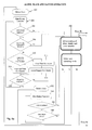
- FIGS. 8 a and 8 b are flow chart depicting the functions of the battery management system and method of the preferred embodiments taught herein;
- FIG. 9 is a flow chart of the preferred embodiment of method of determining master and slave batteries for the system and method of FIGS. 8 a and 8 b.
- the teachings disclosed herein are directed to coupling a plurality of batteries together in a stack in order to increase the capacity of a battery-based power supply to an electrical device.
- the stack can provide greater current to the device and/or can power the device for a greater length of time than can a single battery. This improvement can be achieved even with batteries having a relatively low capacity or current rating.
- FIG. 1 With reference to FIG. 1 , there are shown three batteries 10 , which in this example are identical in their characteristics, coupled together mechanically and electrically in parallel. The couplings, therefore, are such that the potential difference across the battery terminals remains the same but the total current rating of the batteries is, in this example, multiplied threefold. Other embodiments may provide for electrical coupling of batteries in series in order to increase potential difference.
- each battery has a female terminal block as well as a male terminal block.
- the batteries 10 therefore, are substantially identical in their structures, so as to be connectable in any order and such that a virtually unlimited number of batteries 10 can be coupled together.
- a variety of coupling arrangements could be devised although a preferred arrangement (shown in schematic form in FIGS. 5 and 6 ) is described in the applicant's co-pending British patent application no. 1115203.0 filed on 2 Sep. 2011. It is to be understood, however, that the mechanical coupling arrangement is not the focus of the present disclosure.
- the batteries 10 hereinafter referred to as a stack, are shown coupled to a professional camera 12 .
- the number of batteries 10 in the stack can be chosen according to the needs and use of camera 12 , from a single battery in some instances to a large number. It will be appreciated, of course, that there is likely to be a practical limit to the number of batteries which can be stacked together, dependent for example on weight, usage of the device and so on. There is, however, no theoretical limit to the number of batteries which can be stacked.
- FIGS. 3 and 4 show two different battery chargers, 14 and 16 respectively, designed for charging a plurality of batteries 10 .
- the batteries 10 can be controlled by the battery management system and method disclosed herein in a manner which allows charging of the batteries 10 when they are stacked together.
- Existing battery systems requires the batteries to be charged individually.
- a greater number of batteries can be charged simultaneously by a charger 14 , 16 , than with prior art arrangements.
- FIGS. 5 and 6 show, respectively, front and rear views of an embodiment of battery 10 according to the teachings herein. Specific details of the structure of the battery 10 can be found, as explained above, in the applicant's co-pending British patent application no. 1115203.0 filed 2 Sep. 2011.
- the front face 20 of battery 10 has extending out therefrom a female terminal block 22 , which lies substantially horizontally with respect to the base 24 of the battery.
- the female terminal block 22 includes, in this example, four female terminals which provide, respectively, a positive power terminal 26 , a communications line 28 , a link detect line 30 and a negative power terminal 32 .
- the negative terminal 32 will generally be at nominal ground.
- the battery 10 may typically produce 14 to 17 volts across its positive and negative terminals 26 , 32 .
- the female terminals 26 , 32 are, in this embodiment, channels or bores through the terminal block 22 which are lined with a tubular or annular female connector for receiving an associated male electrical terminal.
- the female connectors are coupled to the circuitry in the battery as well as to the battery cells.
- FIG. 6 there is shown in schematic form the rear side 34 of battery 10 of FIG. 5 .
- This side 34 has a recess 36 of a depth preferably sufficient to accommodate the projection of the female terminal dock 22 .
- a plurality of male terminal pins 38 - 44 which in this example are four in number, as per the female terminals 26 - 32 .
- the male terminal pins include a positive voltage terminal 38 , a communications line terminal 40 , a battery status terminal 42 and a negative or nominal ground terminal 44 .
- the pins of the terminals 38 - 44 are positioned and sized so as to fit into respective female terminals 26 - 32 and in particular such that: the positive female terminal 26 couples to the positive male terminal 38 of two batteries 10 coupled together; the female communications line terminal 28 couples to the male communications line terminal 40 ; the female link detect terminal 30 couples to the male battery status terminal 42 ; and the female negative terminal 32 couples to the negative male terminal 44 .
- the arrangement of female and male terminals can be transposed, such that the male terminals are located at the front face 20 of the battery 10 and the female terminals on the rear face 34 .
- the terminals are male or female is immaterial to the teachings herein, as long as a plurality of batteries 10 can be coupled together in a sequence of the type shown in FIG. 1 .
- any number of batteries 10 can be coupled together in a stack.
- the coupling is preferably such that the capacity (Watt-hours) increases with the number of batteries stacked together, thereby to provide greater current and/or greater operating time of the stack to a given electrical device.
- FIG. 7 there is shown in schematic form the principal components of battery 10 .
- These include a control unit 50 and a plurality of cells 52 , for instance of lithium ion (Li-ion).
- the cells 52 can be of conventional form and therefore are not described in any further detail herein.
- Each battery 10 also preferably includes a user interface 54 , which may include a display and/or input keys for operating or determining the status of the battery 10 .
- a user interface 54 may include a display and/or input keys for operating or determining the status of the battery 10 .
- the structure and functionality of the control unit 50 and user interface unit 54 will be apparent from the disclosure below.
- Each battery 10 is, in the preferred embodiment, configurable as an “alone”, a “master” or a “slave” battery, on the basis of the control system and method described below.
- a plurality of batteries 10 When a plurality of batteries 10 is coupled together, one battery 10 becomes the master battery or master controller, while the other batteries 10 act as slaves under the control of the master battery.
- each battery 10 has precisely the same structure and configuration, such that any battery 10 of a plurality of batteries at the disposal of a user can be configured as a master battery of any one stack. It is preferred that all the batteries are, for all purposes, the same in their functionality and ability to be configured.
- the batteries preferably self-configure, as taught below, such that the user does not have to choose a particular master or slave battery.
- the batteries 10 could be operated by a master control unit which is not a battery.
- the electrical device to be powered by the battery stack may include a controller able to act as the master controller for the stack of batteries.
- the control units of the batteries of the stack would configure themselves as slaves to that controller, even if they have the ability to be configurable as the master control unit.
- the embodiments described herein are able to behave in this manner.
- FIGS. 8 a and 8 b show a flow chart explaining the operation of the control units 50 of the batteries 10 in all their configurable states, that is as a battery acting alone, as a slave or as a master. Operation as battery acting alone or as a slave is shown in FIG. 8 a , whereas a control unit acting as a master is shown in FIG. 8 b .
- These three operating states all refer to a routine 100 for determining the operating state of each battery and which is described below in connection with FIG. 9 .
- FIGS. 8 a , 8 b and 9 the hardware, firmware and software to effect the functionality shown in FIGS. 8 a , 8 b and 9 is part of and carried out by the control unit 50 of the battery 10 .
- the hardware components required for the control unit are standard in the art and therefore not described in detail herein.
- sub-routine 102 operates when there is only one battery coupled to an electrical device. This subroutine is also the default state of the batteries 10 .
- the control unit 50 of a battery 10 carries out standard battery functions not directly related to the control of the battery or a stack of batteries. These functions include, for example, determining the capacity of the battery, charge status (typically as Watt-hours and/or percentage total charge), battery type, battery temperature and other functions commonly associated with smart batteries. These functions typically provide to an electrical device data related the battery for use by the device and reference by the user of the device. Data signals from the battery 10 will be transmitted by the battery's status terminal 42 (as shown in FIG. 6 ) or by a separate electrical terminal of the battery (not shown) matched to the electrical terminals of the electrical device to be powered by the battery 10 . In the latter case, the battery 10 may be provided with a plurality of other terminals, for instance at is base 24 , compatible with the electrical device and, of course, coupled internally to the terminals 26 - 32 and 38 - 44 as appropriate.
- control unit 50 of the battery 10 will determine whether its communication line 28 in the female terminal block 22 has been pulled low. This line is normally kept high and would be pulled to a low voltage only when another battery is coupled thereto. If at step 106 it is determined is that the communication line has not been pulled low, the routine passes to step 108 .
- the control unit 50 of battery 10 determines whether the link detector terminal 30 of the female terminal block 22 is at a low or high voltage. This line is normally kept at a low voltage. If it is detected to be low, sub-routine 102 returns to step 104 .
- the routine passes to the routine 100 to effect a determination of the status that battery 10 and any other batteries coupled thereto.
- the reason for this is that the link detector terminal 30 would be pulled high by when another battery is connected to it, given that the link detector 30 would become connected to the battery status terminal 42 of the other battery.
- sub-routine 102 circles through steps 104 - 108 , that battery will behave as a conventional battery, powering an electrical device and providing the conventional battery functions, indicated above, to the electrical device.
- sub-routine 102 would trigger the operation of routine 100 for the following reasons.
- the second battery has some charge, its battery status terminal 42 , which would be connected to the link detect terminal 30 of the first battery, would pull the link detect terminal 30 above 0 volts, thereby triggering a yes determination at step 108 of sub-routine 102 .
- a battery or stack of batteries periodically pulls the communication line(s) 40 low, thereby triggering a low detection at the communication line 28 of coupled batteries and giving a positive determination at step 106 .
- the first battery which would have been acting in an alone status, will be reset to a new operating mode. This will occur substantially instantly when the link detector terminal 30 is pulled high and periodically when the communication line 28 is pulled low, thereby to effect the determination of linked batteries both for a battery which is first in the stack and a newly connected battery.
- this shows the routine 100 which determines which battery is to be designated as the master battery and which configures the other batteries in the stack as slave batteries.
- Routine 100 also assigns a unique identifier, preferably a position number in the stack, to each of the batteries 10 in the stack.
- the routine 100 is entered from the battery alone sub-routine 102 , from the battery slave sub-routine 202 and from the battery master sub-routine 302 , the latter two being described in detail below.
- the first step of routine 100 sets the communication line 40 of all the batteries to a low voltage for a finite period, for example one second. This period can be of any length which will force a new determination procedure to take place. As soon as a determination is made that at least one of the batteries in a stack is not alone (typically from sub-routine 102 ) there would be at least two batteries 10 connected together and therefore setting the communication line 40 of both low for finite period can effect a determination for all of the batteries simultaneously.
- the control units 50 of all the batteries 10 monitor whether their communication line 28 / 40 goes high after the finite low period of step 120 . Where the communication line 28 of one battery is coupled to the communication line 40 of another battery in the stack, that battery will detect its line 28 going high. On the other hand, the last battery in a stack, that is one which has an exposed female terminal block 22 and no electrical couplings thereto, the communication line 28 of that battery will not go high. In this event, at step 124 , that battery will determine that it is the first battery in the stack and, in this example, the battery furthest from the electrical device powered by the stack of batteries. That battery is given a first identifier, for example battery zero (0).
- the first battery in the stack then cycles its battery status line 42 high and low for a finite period (for example one second). That cycling of the battery status line 42 will be detected by the link detect terminal 30 of the next battery coupled thereto, if there is such a battery. In this event, the coupled battery returns to the first battery, via communication terminals 28 and 40 , a signal indicative that it has detected the cycling of the battery status line 42 .
- the first battery which has cycled its battery status line 42 in step 126 , waits for a responses for the next battery in the series. If that response is received, the battery of step 126 is, at step 130 , designated as a slave battery.
- the first battery which is designated as a slave battery is the battery which is given the first identifier, in this example identifier 0.
- the battery which is coupled to battery 0 is given in step 128 the next identifier in the sequence, in this example battery 1 .
- step 128 determines whether the battery which has cycled its battery status line 42 high and low receives no response from a subsequent battery in the stack sequence.
- determination step 128 moves to step 134 to designate that battery as the master battery. This occurs, it will be appreciated, when the last battery in the stack does not get a response through its communications line that a battery has detected the cycling which it has effected on its battery status line 42 .
- steps 126 - 132 will repeat throughout the whole set of batteries in a stack until the very last battery is reached, such that all but the last battery are set as slave batteries and the last is configured as the master.
- this sub-routine is affected for each battery which is set as a slave battery in the stack, that is all but the master battery.
- each slave battery performs its conventional battery functions including, for example, determining its charge status, temperature and so on, and transmits that data through battery status line 42 .
- all of the batteries in a stack are time synchronised so that the data in each slave battery 10 is transferred in an orderly manner to the master battery for processing. That data will be accompanied, in a manner which will be evident to the person skilled in the art, with that battery's unique identifier.
- the (or each) slave battery determines whether its communication line 28 is held low. If so, indicating a new battery in the stack, sub-routine 202 is exited and routine 100 performed again. If, on the other hand, it is not detected at step 206 that the communication line 28 of the slave battery is held low, the routine passes to step 208 , which is a determination carried out by the first battery in the stack, that is battery 0 . At step 208 , therefore, if the identifier is 0 and it is determined that the link detect terminal 30 of that battery is high, sub-routine 202 is exited and routine 100 repeated. The reason is that if the link detect terminal 30 of battery 0 is pulled up, this is indicative of a new battery having been added to the stack and thus of it being necessary to reassign the battery statuses and battery identifiers.
- sub-routine 202 proceeds to steps 210 - 218 , which monitors for requests from the master battery and also carries out any instructions from the master battery. If the master fails to provide any instructions, sub-routine 202 is exited as explained hereinafter.
- each slave battery determines whether it has received an instruction from the master battery. If it has, the routine passes to step 212 , which clears a timeout counter of that slave and then passes to step 214 where the instruction received from the master is actioned. On the other hand, if no instruction has been received from the master, the routine passes to step 216 , where the timeout counter is incremented by one. It will be appreciated that the master battery will send an instruction to every slave within the pre-set count period even if the instruction is not to supply current. (The instruction may just be a status request).
- step 218 if at step 218 it is determined that the timeout counter has reached a threshold number of periods, in this example 3, sub-routine 212 is exited, on the basis that there has been loss of connection with the master. On the other hand, if the timeout counter has not reached the threshold count, this is example 3, sub-routine 202 is repeated.
- sub-routine 202 is carried out by every slave battery in the stack and thus, enables every slave to perform its functions (deliver charge) as and when instructed to do so by the master battery.
- the master does not have to be a battery but in some embodiments could be a separate control unit or a part of the electrical device to be powered by the battery stack. In such a case, the master would not perform any battery related functions but would simply perform the control functions set out in the flow chart of FIG. 8 b.
- the master battery will perform the normal battery functions of determining charge status, capacity, remaining time and so on, and will provide this data to the electrical device coupled thereto.
- the control unit 50 of the master battery will provide indications on the basis of all of the batteries in the stack and therefore combined charge, combined capacity and so on.
- the electrical device sees a single indication of battery status from the master control unit and, in practice, a battery of substantial capacity and charge.
- the master battery determines if its communication line 28 is held low, which may be indicative of another battery having been connected to it or to the stack. If so, sub-routine 306 is exited and routine 100 performed again in order to determine the status and sequence order of the batteries in the stack as well as to reassign unique identifiers to the batteries.
- step 306 reaches a negative determination and sub-routine 302 passes to step 308 .
- the master control unit 50 queries each slave battery to obtain, for example, the state of charge, maximum battery capacity (enabling batteries of different capacity to be stacked together), current draw of the batteries and battery temperature.
- the master battery synchronises the battery timers of all of the batteries in the stack.
- the control unit 50 of the master battery stores the data collected at step 308 in a table identifying the results of each query with the relevant battery identifier. If the master battery has failed to receive a response from one of the slave batteries to its queries step 308 , at step 312 the master battery increments a counter for that slave battery. At step 314 , the master control unit determines whether any slave battery has failed to respond within a predetermined number of periods, this example within 3 periods although that number can be different in other embodiments.
- routine 100 is performed again, on the basis that a failure to respond may be indicative of one or more slave batteries having been removed from the stack.
- routine 100 is performed to reassign battery statuses and battery identifiers.
- the master will trigger to its steady state, that is to a battery alone status, and then perform repeatedly sub-routine 102 until it is detected that another battery has been attached to the single battery.
- step 314 the master controller determines that no slave has failed for the predetermined numbered periods, it passes to step 318 , in which the master battery sorts all of the batteries in the stack by charge status, typically in accordance with the table generated at step 312 . It is preferred that when the master is a battery, it includes its charge status in the table generated at step 310 , and thus sorts itself also at step 318 . However, it is not excluded that in some embodiments the master battery would always retain some charge, irrespective of the charge status of any other batteries connected to it, in order to allow for any and all slave batteries to be removed from the stack for replacement with charged batteries, while still retaining (in the master battery) sufficient charge for powering the electrical device. Thus, the electrical device can remain powered on during replacement of batteries in the stack. This can provide for substantially continuous and uninterrupted power to an electrical device by regular replacement of discharged batteries with charged batteries.
- step 320 is an optional step, in which the master battery determines a total charge and total current deliverable by the battery stack that stores this in a table or other registry to enable a rapid answer if this data is requested from an external source, typically, an electrical device coupled to the battery stack.
- the master battery determines if any of a predetermined set of parameters of one or more of the batteries in the stack exceeds predetermined limits. These may be, for example be the current delivered by the operating batteries, the temperature of any battery or any other parameter limit which it is desirable to monitor.
- sub-routine 302 passes to step 324 , at which all or some of the slave units are shut down as required in order to ensure that those parameter limits of step 322 are no longer breached.
- This sequence is particularly important, in that it allows the provision of a battery stack having a much higher current capacity than that required for an electrical device coupled to the electrical device. Specifically, if for instance the maximum current capacity for safe operation of an electrical device happens to be total current deliverable by, for example, two batteries; a stack of more than two batteries, 5 , 6 or 8 for example (even more), can be coupled to the stack but by steps 322 , 324 , the master controller will power on only two of the batteries and power off all of the others in the stack. This will ensure that the electrical device is not supplied with more than the acceptable level of current.
- the master battery will ensure that the electrical device continues to be supplied with sufficient current during the course of discharge of the individual batteries in the stack. It is thus possible to connect to an electrical device a relatively large number of batteries, which are able to provide power for the device for a very long time and many times more than arrangements or other combinations in which the operation of the batteries cannot be controlled in this manner.
- step 326 the routine passes to step 326 .
- the master battery determines whether the total current associated with the battery stack, determined for example step 320 , is indicative of the batteries discharging or charging.
- the sub-routine passes to step 328 , that is to a discharge mode.
- master control unit connects only, in this example, the two batteries with the greater state of charge, as determined at step 318 .
- the number of batteries which will be instructed to provide power will, of course, be dependent upon the capacity of the individual batteries and the power requirement of the electrical device to which they are connected. Thus, in some examples only a single battery may provide current, whereas in other examples more than two batteries may be provide current.
- the master control unit will set any or all other batteries in the stack which are not to provide power in a non-powering state.
- the master control unit 50 or battery performs the following functions.
- the master battery 50 makes regular communications with its slave batteries 10 . There are a few reasons for this. The first is to confirm to the slave batteries 10 that they are still correctly linked to the master, by the virtue of being communicated with. A second is to allow the master battery 10 maintain a valid table of all connected battery details from which it will create any data transmitted to the application. A third is to transfer the requested connection status to each battery 10 .
- the periodic request may be in the form of a question (a request for basic information to be returned).
- the question is sent along with data, showing the current time to run prediction (so the slave battery 10 can display this figure to the user upon request via its user interface unit 54 ) and next connection request.
- Each slave battery 10 replies to the master battery's request with the information. This confirms each slave battery has also received the next connection status request.
- the master battery 10 When the master battery 10 has determined that all the slave batteries 10 have confirmed reception of this data, it will transmit a message for all the batteries 10 to action the connection status. The master battery 10 will at this point action its own status as part of the battery stack.
- Each battery 10 will action a request to be connected immediately and a request for a disconnection after a set number of milliseconds. This ensures that the electrical device is never without power. The duration of such power crossover is slight and the number of batteries switched is limited so as to prevent damage to the electrical device or any large deviation in output voltage.
- the sub-routine returns back to step 304 and is repeated again.
- the master battery will continue to provide power to an electrical device to which it is connected, in this example selecting always the two batteries which have the greatest states of charge. As those batteries become discharged, the control unit will select other batteries which will then be the most charged. In practice, the master battery will activate any “new” batteries to discharge before instructing a discharging battery to deactivate, thereby not to interrupt the power to the electrical device connected to the battery stack.
- the master controller sets, at step 332 , the charge mode.
- the master controller connects to the electrical device only that battery having the lowest state of charge.
- the control unit may connect more than one battery but preferably those having the lowest charge status as determined at step 318 .
- Steps 332 and 334 are relevant for charging of the batteries in particular when the batteries are connected to a charging unit in the arrangement shown, for example, in FIGS. 3 and 4 . This has the advantage of enabling batteries in stacked configuration to be coupled to a charger and be charged together.
Landscapes
- Engineering & Computer Science (AREA)
- Power Engineering (AREA)
- Chemical & Material Sciences (AREA)
- Chemical Kinetics & Catalysis (AREA)
- Electrochemistry (AREA)
- General Chemical & Material Sciences (AREA)
- Manufacturing & Machinery (AREA)
- Charge And Discharge Circuits For Batteries Or The Like (AREA)
- Secondary Cells (AREA)
Applications Claiming Priority (2)
| Application Number | Priority Date | Filing Date | Title |
|---|---|---|---|
| GB1115200.6A GB2494187B (en) | 2011-09-02 | 2011-09-02 | Battery management system, method and battery |
| GB1115200.6 | 2011-09-02 |
Publications (2)
| Publication Number | Publication Date |
|---|---|
| US20130057076A1 US20130057076A1 (en) | 2013-03-07 |
| US9641002B2 true US9641002B2 (en) | 2017-05-02 |
Family
ID=44882136
Family Applications (1)
| Application Number | Title | Priority Date | Filing Date |
|---|---|---|---|
| US13/525,880 Active 2034-09-09 US9641002B2 (en) | 2011-09-02 | 2012-06-18 | Battery management system, method and battery |
Country Status (3)
| Country | Link |
|---|---|
| US (1) | US9641002B2 (de) |
| EP (1) | EP2587619B1 (de) |
| GB (2) | GB2526005B (de) |
Cited By (19)
| Publication number | Priority date | Publication date | Assignee | Title |
|---|---|---|---|---|
| US20170005501A1 (en) * | 2015-07-01 | 2017-01-05 | Maxim Integrated Products, Inc. | Master Slave Charging Architecture With Communication Between Chargers |
| USD813815S1 (en) * | 2015-10-28 | 2018-03-27 | Mitsubishi Electric Corporation | Storage battery |
| US20180241237A1 (en) * | 2015-10-22 | 2018-08-23 | Innogy Innovation Gmbh | Mobile Electric Storage Device |
| US10714954B2 (en) * | 2014-09-24 | 2020-07-14 | Powertec Solutions International Llc | Portable switching power supply with attachable battery pack and enclosure |
| US10938221B1 (en) | 2020-06-02 | 2021-03-02 | Inventus Power, Inc. | Large-format battery management system with limp home mode |
| US11211806B2 (en) * | 2017-02-16 | 2021-12-28 | Sz Dji Osmo Technology Co., Ltd. | Power supply method, power supply device, and electronic device |
| US11223217B2 (en) * | 2016-12-28 | 2022-01-11 | Hubbell Incorporated | Modular device charging system |
| US11245268B1 (en) | 2020-07-24 | 2022-02-08 | Inventus Power, Inc. | Mode-based disabling of communiction bus of a battery management system |
| US11404885B1 (en) | 2021-02-24 | 2022-08-02 | Inventus Power, Inc. | Large-format battery management systems with gateway PCBA |
| US11411407B1 (en) | 2021-02-24 | 2022-08-09 | Inventus Power, Inc. | Large-format battery management systems with gateway PCBA |
| US11476677B2 (en) | 2020-06-02 | 2022-10-18 | Inventus Power, Inc. | Battery pack charge cell balancing |
| US11489343B2 (en) | 2020-06-02 | 2022-11-01 | Inventus Power, Inc. | Hardware short circuit protection in a large battery pack |
| US11509144B2 (en) | 2020-06-02 | 2022-11-22 | Inventus Power, Inc. | Large-format battery management system with in-rush current protection for master-slave battery packs |
| US11552479B2 (en) | 2020-06-02 | 2023-01-10 | Inventus Power, Inc. | Battery charge balancing circuit for series connections |
| US11588334B2 (en) | 2020-06-02 | 2023-02-21 | Inventus Power, Inc. | Broadcast of discharge current based on state-of-health imbalance between battery packs |
| US11594892B2 (en) | 2020-06-02 | 2023-02-28 | Inventus Power, Inc. | Battery pack with series or parallel identification signal |
| US20230229122A1 (en) * | 2012-06-26 | 2023-07-20 | Black & Decker Inc. | System, device and process for programming power tools |
| US12224603B2 (en) | 2020-06-02 | 2025-02-11 | Inventus Power, Inc. | Mode-based disabling of communication bus of a battery management system |
| US12301031B1 (en) | 2020-06-02 | 2025-05-13 | Inventus Power, Inc. | Large-format battery management systems with gateway PCBA |
Families Citing this family (21)
| Publication number | Priority date | Publication date | Assignee | Title |
|---|---|---|---|---|
| GB2526005B (en) | 2011-09-02 | 2016-04-06 | Pag Ltd | Battery management system, method and battery |
| US9653719B2 (en) | 2013-10-04 | 2017-05-16 | Pag Ltd. | Battery |
| JP6245947B2 (ja) | 2013-11-06 | 2017-12-13 | ヤマハ発動機株式会社 | 車両及びバッテリパック |
| WO2016134487A1 (de) | 2015-02-23 | 2016-09-01 | Wetrok Ag | Verfahren und vorrichtung zur steuerung und überwachung von batterien |
| FR3033452B1 (fr) | 2015-03-03 | 2018-04-06 | Renault S.A.S. | Procede et systeme d'allocation d'une requete de puissance a une pluralite de batteries connectees en parallele |
| US10197630B2 (en) * | 2015-04-10 | 2019-02-05 | Ross Kanarek | Wireless smart battery system |
| US10498150B2 (en) * | 2015-11-04 | 2019-12-03 | Cps Technology Holdings Llc | Hybrid battery control system architecture design systems and methods |
| CN105429224A (zh) * | 2015-12-16 | 2016-03-23 | 常州格力博有限公司 | 一种支持多个电池包的电气系统 |
| GB2554788B (en) * | 2016-05-26 | 2019-03-06 | Hyperdrive Innovation Ltd | Methods and apparatus for energy storage |
| EP3264491A1 (de) * | 2016-06-28 | 2018-01-03 | Wattsun pop-up power B.V. | Modulares energiesystem zur speicherung und abgabe von energie |
| CN108963353A (zh) | 2017-05-26 | 2018-12-07 | 宁德时代新能源科技股份有限公司 | 电池包的主从识别方法及装置 |
| EP3407458B1 (de) * | 2017-05-26 | 2020-09-09 | Contemporary Amperex Technology Co., Limited | Verfahren und vorrichtung zur identifizierung von master- und slave-batteriepacks |
| WO2019017020A1 (ja) * | 2017-07-19 | 2019-01-24 | パナソニックIpマネジメント株式会社 | 電子機器及び電子システム |
| US10680446B2 (en) | 2017-08-25 | 2020-06-09 | Black & Decker Inc. | Battery pack charger system |
| KR102401481B1 (ko) * | 2017-12-22 | 2022-05-24 | 삼성전자주식회사 | 가전 기기 및 이를 제어하는 제어 방법 |
| JP6522843B1 (ja) * | 2018-10-09 | 2019-05-29 | 株式会社アイ・ディー・エクス | バッテリ充電システムおよびその制御方法 |
| LU101735B1 (de) * | 2020-04-15 | 2021-10-15 | Betteries Amps Gmbh | Verfahren zum Betreiben einer Vorrichtung zum Zuführen oder Abführen von elektrischer Energie |
| WO2022078420A1 (en) * | 2020-10-16 | 2022-04-21 | Globe (jiangsu) Co., Ltd. | Charger, charging device, energy supply device and control method of charger |
| KR102483972B1 (ko) | 2020-11-13 | 2023-01-03 | (주)에너캠프 | 복수개의 배터리팩이 장착된 파워스테이션의 충전 및 방전 제어방법 |
| US11735841B1 (en) | 2022-09-02 | 2023-08-22 | Ross Kanarek | Mount plate for audiovisual devices |
| US11770012B1 (en) | 2022-10-20 | 2023-09-26 | Ross Kanarek | Device, system, and method of charging a battery for audiovisual equipment |
Citations (133)
| Publication number | Priority date | Publication date | Assignee | Title |
|---|---|---|---|---|
| US1536322A (en) | 1921-07-01 | 1925-05-05 | Benjamin Electric Mfg Co | Electrical-fixture-supporting device |
| US1646807A (en) | 1921-08-22 | 1927-10-25 | Benjamin Electric Mfg Co | Fixture connecter |
| US2542404A (en) | 1948-12-16 | 1951-02-20 | Ensign Electric And Mfg Compan | Power distribution system |
| US2899669A (en) | 1959-08-11 | Electrical connector | ||
| US3335330A (en) | 1964-03-13 | 1967-08-08 | Square D Co | Mounting pan assembly for electrical panelboard |
| US3564482A (en) | 1967-07-07 | 1971-02-16 | Matsushita Electric Works Ltd | Hook type surface mounted connector |
| US3588239A (en) | 1968-05-30 | 1971-06-28 | Zeiss Ikon Ag | Motion picture camera with movable handle |
| US3617985A (en) | 1969-10-24 | 1971-11-02 | Motorola Inc | Accessory connector |
| US3668605A (en) | 1970-08-10 | 1972-06-06 | North Electric Co | Multi-point program plug and receptacle connector arrangement having positive alignment prior to positive mating |
| US3728664A (en) | 1971-12-21 | 1973-04-17 | Repco Inc | Battery latching mechanism |
| US3740696A (en) | 1970-06-23 | 1973-06-19 | Schleicher Gmbh & Co | Locking mechanism |
| FR2179445A5 (de) | 1972-04-05 | 1973-11-16 | Semperit Ag | |
| US3836885A (en) | 1972-06-13 | 1974-09-17 | Technilec Sarl | Electrical connectors |
| US3967303A (en) | 1974-12-16 | 1976-06-29 | Polaroid Corporation | Accessory attachment for cameras |
| US3969796A (en) | 1975-09-17 | 1976-07-20 | General Electric Company | Releasable fastening arrangement for a radio housing and a battery housing |
| US3984169A (en) | 1972-03-10 | 1976-10-05 | Harvey Hubbell Incorporated | Keying for lever action connectors |
| US3997092A (en) | 1974-11-18 | 1976-12-14 | Pogwizd Kenneth W | Paint container carrier |
| DE2542933A1 (de) | 1975-09-26 | 1977-03-31 | Bock Orthopaed Ind | Akkumulator zum einbau in eine elektrische fremdkraftprothese |
| FR2333267A1 (fr) | 1975-11-29 | 1977-06-24 | Balda Werke Photographische | Appareil photographique a flash electronique |
| US4050003A (en) | 1974-08-23 | 1977-09-20 | The Black And Decker Manufacturing Company | Modular cordless tools |
| FR2360778A1 (fr) | 1976-08-06 | 1978-03-03 | Balda Werke Photographische | Dispositif de liaison pour supporter des accessoires, notamment des appareils a lampe eclair, sur des appareils photographiques |
| US4085253A (en) | 1975-05-27 | 1978-04-18 | Polaroid Corporation | Battery assembly |
| GB1532748A (en) | 1976-07-29 | 1978-11-22 | Ncr Co | Electrical connectors |
| EP0003649A1 (de) | 1978-02-03 | 1979-08-22 | AMP INCORPORATED (a New Jersey corporation) | Elektrischer Steckverbinder mit polarisiert gestaltetem Gehäuse |
| GB2026086A (en) | 1978-06-13 | 1980-01-30 | Yoshida Kogyo Kk | Lockable slider for a slide fastener |
| GB1571061A (en) | 1976-03-25 | 1980-07-09 | Syntronic Ag | Electrical connectors |
| US4218107A (en) | 1979-05-11 | 1980-08-19 | Anton/Bauer, Inc. | Battery pack connection |
| US4261495A (en) | 1978-09-01 | 1981-04-14 | Mueller Christoph | Bag construction |
| JPS5654754A (en) | 1979-10-09 | 1981-05-14 | Mitsubishi Electric Corp | Battery fixing structure |
| GB2071515A (en) | 1979-12-07 | 1981-09-23 | Disab Vacuumteknik Ab | Vacuum loading apparatus |
| GB2083296A (en) | 1980-08-19 | 1982-03-17 | Bosch Gmbh Robert | A plug and socket device |
| US4329962A (en) | 1980-09-29 | 1982-05-18 | General Motors Corporation | Diesel injection pump timing control with eccentric cam pin |
| US4340267A (en) | 1980-06-13 | 1982-07-20 | Tokuji Nukaga | Safety electrical plug |
| JPS58152231A (ja) | 1982-03-05 | 1983-09-09 | Konishiroku Photo Ind Co Ltd | 異種電池が使用可能なカメラ |
| US4420207A (en) | 1980-05-28 | 1983-12-13 | Yamaichi Electric Mfg. Co., Ltd. | Socket having means of no-load engaging with and releasing from electronic unit |
| US4431245A (en) | 1982-01-11 | 1984-02-14 | Christie Electric Corporation | Connector for battery pack |
| US4452383A (en) | 1981-06-25 | 1984-06-05 | Marttinen Toivo O | Carrying device for pot plant cell units |
| EP0118598A2 (de) | 1982-11-24 | 1984-09-19 | Accumulatorenfabrik Sonnenschein Gmbh | Einsetzteil für ein Schubfach |
| JPS59175554A (ja) | 1983-03-25 | 1984-10-04 | Hitachi Koki Co Ltd | 電池式丸のこ盤の電池収納カバ− |
| US4518217A (en) | 1983-04-08 | 1985-05-21 | Bauer Anton | Electrical connector and receptacle |
| JPS60150771A (ja) | 1984-01-20 | 1985-08-08 | 池田 寛 | パチンコ台の管理システム |
| EP0152650A1 (de) | 1984-01-09 | 1985-08-28 | Koninklijke Philips Electronics N.V. | Ladevorrichtung |
| US4545414A (en) | 1984-02-21 | 1985-10-08 | Baum Frank M | Belt-supported camera bag |
| US4550968A (en) | 1984-10-12 | 1985-11-05 | Anton/Bauer, Inc. | Battery pack connection |
| US4554221A (en) | 1985-01-23 | 1985-11-19 | Dsl Dynamic Sciences Limited | Rechargeable battery pack |
| US4554500A (en) | 1983-03-31 | 1985-11-19 | Anton/Bauer, Inc. | Battery charging apparatus and method |
| US4554621A (en) | 1984-10-29 | 1985-11-19 | Anton/Bauer, Inc. | Modular light assembly |
| US4586766A (en) | 1984-03-02 | 1986-05-06 | Robert Bosch Gmbh | Multi-terminal plug-socket connection arrangement |
| US4616169A (en) | 1985-04-08 | 1986-10-07 | Scovill Inc. | Battery-powered appliance |
| US4709974A (en) | 1985-10-15 | 1987-12-01 | Pag Limited | Battery connector |
| US4810199A (en) | 1987-11-25 | 1989-03-07 | Kar Kishore K | Safety electrical plug |
| US4810204A (en) | 1987-03-26 | 1989-03-07 | Anton/Bauer, Inc. | Battery pack connection |
| US4822296A (en) | 1987-06-19 | 1989-04-18 | Anton/Bauer, Inc. | Electrical connection for battery charging apparatus or the like |
| US4836799A (en) | 1987-03-04 | 1989-06-06 | Tomer Jitendra P | Electrical cable connector |
| US4849682A (en) | 1987-10-30 | 1989-07-18 | Anton/Bauer, Inc. | Battery charging system |
| US4878606A (en) | 1981-01-09 | 1989-11-07 | Murlyn Enterprises Ltd. | Harness for shoulder supported bag |
| GB2223134A (en) | 1988-04-07 | 1990-03-28 | Pag Ltd | Electrical plug and socket connector |
| US4965738A (en) | 1988-05-03 | 1990-10-23 | Anton/Bauer, Inc. | Intelligent battery system |
| US5007848A (en) | 1989-08-01 | 1991-04-16 | Lee Chiu Shan | Multipurpose safety receptacle |
| US5038093A (en) | 1990-09-27 | 1991-08-06 | Gates Energy Products, Inc. | Rechargeable cell terminal configuration and charging device |
| EP0448767A1 (de) | 1990-03-30 | 1991-10-02 | Anton/Bauer, Inc. | Batteriesystem |
| US5089834A (en) | 1988-05-16 | 1992-02-18 | Minolta Camera Kabushiki Kaisha | Mounting devices for removably mounting an accessory on a camera |
| US5104752A (en) | 1990-10-15 | 1992-04-14 | Allied-Signal, Inc. | Dual, series/parallel battery cell connects |
| US5135406A (en) | 1990-08-13 | 1992-08-04 | U.S. Philips Corp. | Rechargeable electric apparatus |
| GB2253513A (en) | 1989-10-11 | 1992-09-09 | Alan Roy Cooke | Portable power supplies |
| EP0504713A1 (de) | 1991-03-12 | 1992-09-23 | HERRMANN GmbH | Vorrichtung zur Aufnahme einer Batterieanordnung und einer zugehörigen Schaltungsanordnung |
| EP0506439A1 (de) | 1991-03-29 | 1992-09-30 | Nec Corporation | Aufladevorrichtung |
| US5195666A (en) | 1990-10-08 | 1993-03-23 | Sumiko Yamaguchi | Waist bag |
| GB2260040A (en) | 1991-09-28 | 1993-03-31 | Fu Ching Wang | Battery charger |
| JPH05159755A (ja) | 1991-12-02 | 1993-06-25 | Honda Motor Co Ltd | 車両用バッテリ |
| GB2263362A (en) | 1992-01-06 | 1993-07-21 | Pag Ltd | Radio interference suppression device |
| US5233281A (en) | 1991-12-02 | 1993-08-03 | Wen-Chi Chiang | Replaceable cartridge type high speed nickel-cadmium battery charger |
| EP0559573A1 (de) | 1992-03-06 | 1993-09-08 | Sony Corporation | Batteriepack |
| US5251329A (en) | 1990-03-07 | 1993-10-05 | Sony Corporation | Radio telephone apparatus with microphone mounted in battery case |
| US5256954A (en) | 1992-07-09 | 1993-10-26 | Jeff Chen | Battery pack charging device |
| US5287052A (en) | 1992-09-01 | 1994-02-15 | Wang Fu C | Size adjustable battery charger |
| GB2270832A (en) | 1992-09-29 | 1994-03-30 | Pag Ltd | Battery pack |
| JPH06104814A (ja) | 1992-09-18 | 1994-04-15 | Fujitsu Ltd | 通信装置 |
| US5306172A (en) | 1985-05-27 | 1994-04-26 | Sony Corporation | Video tape recorder having built-in camera detachable hand grip member |
| US5350993A (en) | 1992-01-20 | 1994-09-27 | Sanyo Electric Co., Ltd. | Power supply |
| US5369565A (en) | 1991-10-04 | 1994-11-29 | Innova Electronics Corp. | Modular power supply system |
| US5403093A (en) | 1993-11-12 | 1995-04-04 | Anton/Bauer, Inc. | DT/Dt detector for cell pack charge determination |
| US5412547A (en) | 1993-12-21 | 1995-05-02 | Dci Marketing | Illuminatable rechargeable display device |
| JPH07143372A (ja) | 1993-11-15 | 1995-06-02 | Sony Corp | ビデオカメラ |
| US5496657A (en) | 1994-03-16 | 1996-03-05 | Dixon, Jr.; Alfred R. | Modular battery system comprising individual interconnected modules |
| JPH08148233A (ja) | 1994-11-17 | 1996-06-07 | Fujikura Ltd | バッテリ用端子 |
| US5592064A (en) | 1992-11-26 | 1997-01-07 | Sanyo Electric Co., Ltd. | Battery charging apparatus, power supply, and attachment for connecting different types of battery packs to a battery charger |
| US5602454A (en) | 1992-09-18 | 1997-02-11 | Sony Corporation | Battery pack having identification recesses and terminals |
| US5613863A (en) | 1995-05-18 | 1997-03-25 | Motorola, Inc. | Power transformer |
| US5616968A (en) * | 1993-12-24 | 1997-04-01 | Omron Corporation | Expandable AC power supply device |
| US5652496A (en) | 1996-02-12 | 1997-07-29 | Rayovac Corporation | Electrical device having a discriminating, rechargeable battery system |
| US5656914A (en) | 1995-10-31 | 1997-08-12 | Motorola, Inc. | Battery charger having pocket with multiple sets of charging contacts |
| US5663012A (en) | 1995-03-08 | 1997-09-02 | Enersafe Corporation | Apparatus for gang-connecting batteries |
| US5777453A (en) | 1995-09-26 | 1998-07-07 | Kabushiki Kaisha Jnt | Method and apparatus for recharging batteries using a step shaped voltage pulse |
| US5816439A (en) | 1995-02-17 | 1998-10-06 | Industrial Containers Ltd. | Container with handle |
| US5821732A (en) | 1997-09-04 | 1998-10-13 | E. Lead Electronic Co., Ltd | Charger device |
| US5844401A (en) | 1996-05-16 | 1998-12-01 | Samsung Electronics Co., Ltd. | Charging device for easy mounting/dismounting of a battery |
| US5917152A (en) | 1996-12-19 | 1999-06-29 | Yazaki Corporation | Door wiring harness connecting structure |
| JPH11191854A (ja) | 1997-12-25 | 1999-07-13 | Sony Corp | ビデオカメラ用ワイヤレスレシーバー取り付けアダプタ |
| US5921797A (en) | 1997-12-17 | 1999-07-13 | The Whitaker Company | Electrical connector for use with removable electronic console |
| GB2335027A (en) | 1998-03-02 | 1999-09-08 | Pag Ltd | Light assembly with removable bulb holder |
| US5959368A (en) * | 1994-10-31 | 1999-09-28 | Fujitsu Limited | Power supply apparatus for supplying power from a plurality of batteries to a plurality of loads, and electronic appliance using the power supply apparatus |
| US6102725A (en) | 1998-09-10 | 2000-08-15 | Panagiotou; George N. | Replaceable battery housing electrical connector assembly |
| US6109938A (en) | 1998-04-09 | 2000-08-29 | Carrier Kheops Bac | Hermaphroditic electrical safety connector |
| US6233141B1 (en) | 1999-01-27 | 2001-05-15 | Compal Electronics Inc. | Securing structure for the battery cartridge of a notebook-type computer |
| US6247962B1 (en) | 1999-04-19 | 2001-06-19 | Anton/Bauer, Inc. | Battery pack connection adapter |
| US6285158B1 (en) | 1996-01-29 | 2001-09-04 | Sony Corporation | Battery discriminating method, dry cell battery pack, and electronic device |
| US6346793B1 (en) | 1999-10-26 | 2002-02-12 | Makita Corporation | Battery charger with a terminal protector |
| US6384575B1 (en) | 2000-11-28 | 2002-05-07 | Delta Electronics, Inc. | Battery charger capable of charging different size of batteries |
| US6457988B1 (en) | 2000-12-21 | 2002-10-01 | Richard S. Eisen | Electrical connector |
| US6489744B2 (en) | 2000-02-09 | 2002-12-03 | Pag Limited | Battery charger with movable battery fitting |
| US6638086B2 (en) | 2000-09-20 | 2003-10-28 | Pag Limited | Configurable battery connector |
| US6749960B2 (en) | 1999-02-17 | 2004-06-15 | Sony Corporation | Battery pack, battery loading device, power supplying device and electronic equipment |
| US6783403B2 (en) | 2002-01-15 | 2004-08-31 | Abb Entrelec | Connection device for an electronic box |
| US6805997B1 (en) | 2000-03-27 | 2004-10-19 | I·D·X Company Ltd. | Battery |
| US6935883B2 (en) | 2002-04-24 | 2005-08-30 | Innovative Office Products, Inc. | Quick interconnection system for electronic devices |
| US20050226741A1 (en) | 2004-04-08 | 2005-10-13 | Wen-Sheng Huang | Engagement terminals for DC power pack and copressor |
| US7064519B2 (en) | 2002-10-21 | 2006-06-20 | Makita Corporation | Battery charger with improved terminal protection |
| GB2425185A (en) | 2005-04-15 | 2006-10-18 | Pag Ltd | Camera support and associated apparatus |
| US20070037456A1 (en) | 2005-08-12 | 2007-02-15 | Burgess James P | Low resistance, low insertion force electrical connector |
| US7271760B2 (en) | 2004-07-14 | 2007-09-18 | Harly-Davidson Motor Company Group, Inc. | Radar detector for a motorcycle |
| US7347714B2 (en) | 2005-08-23 | 2008-03-25 | Hon Hai Precision Industry Co., Ltd. | Electronic device assembly having securing feature |
| US7390211B2 (en) | 1999-08-23 | 2008-06-24 | Jerry Moscovitch | Universal quick connector apparatus for an LCD monitor |
| US20080254670A1 (en) | 2007-04-13 | 2008-10-16 | Balsells Peter J | Electrical connectors with improved electrical contact performance |
| JP2009011138A (ja) | 2007-06-29 | 2009-01-15 | Toyota Motor Corp | 電源システムおよびそれを備えた車両、ならびに電源システムの制御方法およびその制御方法をコンピュータに実行させるためのプログラムを記録したコンピュータ読取可能な記録媒体 |
| US20090146610A1 (en) | 2007-12-11 | 2009-06-11 | Antonio Trigiani | Battery management system |
| EP2164127A1 (de) | 2008-09-03 | 2010-03-17 | Omron Corporation | Mehrzellenbatteriesystem und Verfahren zur Nummerierung der Zellen des Systems |
| US20110025258A1 (en) | 2009-07-29 | 2011-02-03 | The Regents Of The University Of Michigan | System for scheduling battery charge and discharge |
| US8029311B2 (en) | 2008-06-25 | 2011-10-04 | Sony Corporation | Female connector structure, male connector structure, battery, adapter and electric device |
| US20120038322A1 (en) * | 2010-08-11 | 2012-02-16 | A123 Systems, Inc. | Rechargeable Battery Management |
| US8299656B2 (en) | 2008-03-12 | 2012-10-30 | Whirlpool Corporation | Feature module connection system |
| US20130057076A1 (en) | 2011-09-02 | 2013-03-07 | Pag Ltd. | Battery management system, method and battery |
| US20130059477A1 (en) | 2011-09-02 | 2013-03-07 | Pag Ltd. | Battery coupling arrangement |
Family Cites Families (2)
| Publication number | Priority date | Publication date | Assignee | Title |
|---|---|---|---|---|
| US3277830A (en) | 1964-11-02 | 1966-10-11 | Acf Ind Inc | Valved pump |
| GB1115203A (en) | 1964-11-02 | 1968-05-29 | Junghaus Gmbh Geb | Improvements in or relating to electric clock movements |
-
2011
- 2011-09-02 GB GB1512383.9A patent/GB2526005B/en active Active
- 2011-09-02 GB GB1115200.6A patent/GB2494187B/en active Active
-
2012
- 2012-06-18 US US13/525,880 patent/US9641002B2/en active Active
- 2012-09-03 EP EP12275132.4A patent/EP2587619B1/de active Active
Patent Citations (135)
| Publication number | Priority date | Publication date | Assignee | Title |
|---|---|---|---|---|
| US2899669A (en) | 1959-08-11 | Electrical connector | ||
| US1536322A (en) | 1921-07-01 | 1925-05-05 | Benjamin Electric Mfg Co | Electrical-fixture-supporting device |
| US1646807A (en) | 1921-08-22 | 1927-10-25 | Benjamin Electric Mfg Co | Fixture connecter |
| US2542404A (en) | 1948-12-16 | 1951-02-20 | Ensign Electric And Mfg Compan | Power distribution system |
| US3335330A (en) | 1964-03-13 | 1967-08-08 | Square D Co | Mounting pan assembly for electrical panelboard |
| US3564482A (en) | 1967-07-07 | 1971-02-16 | Matsushita Electric Works Ltd | Hook type surface mounted connector |
| US3588239A (en) | 1968-05-30 | 1971-06-28 | Zeiss Ikon Ag | Motion picture camera with movable handle |
| US3617985A (en) | 1969-10-24 | 1971-11-02 | Motorola Inc | Accessory connector |
| US3740696A (en) | 1970-06-23 | 1973-06-19 | Schleicher Gmbh & Co | Locking mechanism |
| US3668605A (en) | 1970-08-10 | 1972-06-06 | North Electric Co | Multi-point program plug and receptacle connector arrangement having positive alignment prior to positive mating |
| US3728664A (en) | 1971-12-21 | 1973-04-17 | Repco Inc | Battery latching mechanism |
| US3984169A (en) | 1972-03-10 | 1976-10-05 | Harvey Hubbell Incorporated | Keying for lever action connectors |
| FR2179445A5 (de) | 1972-04-05 | 1973-11-16 | Semperit Ag | |
| US3836885A (en) | 1972-06-13 | 1974-09-17 | Technilec Sarl | Electrical connectors |
| US4050003A (en) | 1974-08-23 | 1977-09-20 | The Black And Decker Manufacturing Company | Modular cordless tools |
| US3997092A (en) | 1974-11-18 | 1976-12-14 | Pogwizd Kenneth W | Paint container carrier |
| US3967303A (en) | 1974-12-16 | 1976-06-29 | Polaroid Corporation | Accessory attachment for cameras |
| US4085253A (en) | 1975-05-27 | 1978-04-18 | Polaroid Corporation | Battery assembly |
| US3969796A (en) | 1975-09-17 | 1976-07-20 | General Electric Company | Releasable fastening arrangement for a radio housing and a battery housing |
| DE2542933A1 (de) | 1975-09-26 | 1977-03-31 | Bock Orthopaed Ind | Akkumulator zum einbau in eine elektrische fremdkraftprothese |
| FR2333267A1 (fr) | 1975-11-29 | 1977-06-24 | Balda Werke Photographische | Appareil photographique a flash electronique |
| GB1571061A (en) | 1976-03-25 | 1980-07-09 | Syntronic Ag | Electrical connectors |
| GB1532748A (en) | 1976-07-29 | 1978-11-22 | Ncr Co | Electrical connectors |
| FR2360778A1 (fr) | 1976-08-06 | 1978-03-03 | Balda Werke Photographische | Dispositif de liaison pour supporter des accessoires, notamment des appareils a lampe eclair, sur des appareils photographiques |
| EP0003649A1 (de) | 1978-02-03 | 1979-08-22 | AMP INCORPORATED (a New Jersey corporation) | Elektrischer Steckverbinder mit polarisiert gestaltetem Gehäuse |
| GB2026086A (en) | 1978-06-13 | 1980-01-30 | Yoshida Kogyo Kk | Lockable slider for a slide fastener |
| US4261495A (en) | 1978-09-01 | 1981-04-14 | Mueller Christoph | Bag construction |
| US4218107A (en) | 1979-05-11 | 1980-08-19 | Anton/Bauer, Inc. | Battery pack connection |
| JPS5654754A (en) | 1979-10-09 | 1981-05-14 | Mitsubishi Electric Corp | Battery fixing structure |
| GB2071515A (en) | 1979-12-07 | 1981-09-23 | Disab Vacuumteknik Ab | Vacuum loading apparatus |
| US4420207A (en) | 1980-05-28 | 1983-12-13 | Yamaichi Electric Mfg. Co., Ltd. | Socket having means of no-load engaging with and releasing from electronic unit |
| US4340267A (en) | 1980-06-13 | 1982-07-20 | Tokuji Nukaga | Safety electrical plug |
| GB2083296A (en) | 1980-08-19 | 1982-03-17 | Bosch Gmbh Robert | A plug and socket device |
| US4329962A (en) | 1980-09-29 | 1982-05-18 | General Motors Corporation | Diesel injection pump timing control with eccentric cam pin |
| US4878606A (en) | 1981-01-09 | 1989-11-07 | Murlyn Enterprises Ltd. | Harness for shoulder supported bag |
| US4452383A (en) | 1981-06-25 | 1984-06-05 | Marttinen Toivo O | Carrying device for pot plant cell units |
| US4431245A (en) | 1982-01-11 | 1984-02-14 | Christie Electric Corporation | Connector for battery pack |
| JPS58152231A (ja) | 1982-03-05 | 1983-09-09 | Konishiroku Photo Ind Co Ltd | 異種電池が使用可能なカメラ |
| EP0118598A2 (de) | 1982-11-24 | 1984-09-19 | Accumulatorenfabrik Sonnenschein Gmbh | Einsetzteil für ein Schubfach |
| JPS59175554A (ja) | 1983-03-25 | 1984-10-04 | Hitachi Koki Co Ltd | 電池式丸のこ盤の電池収納カバ− |
| US4554500A (en) | 1983-03-31 | 1985-11-19 | Anton/Bauer, Inc. | Battery charging apparatus and method |
| US4518217A (en) | 1983-04-08 | 1985-05-21 | Bauer Anton | Electrical connector and receptacle |
| EP0152650A1 (de) | 1984-01-09 | 1985-08-28 | Koninklijke Philips Electronics N.V. | Ladevorrichtung |
| JPS60150771A (ja) | 1984-01-20 | 1985-08-08 | 池田 寛 | パチンコ台の管理システム |
| US4545414A (en) | 1984-02-21 | 1985-10-08 | Baum Frank M | Belt-supported camera bag |
| US4586766A (en) | 1984-03-02 | 1986-05-06 | Robert Bosch Gmbh | Multi-terminal plug-socket connection arrangement |
| US4550968A (en) | 1984-10-12 | 1985-11-05 | Anton/Bauer, Inc. | Battery pack connection |
| US4554621A (en) | 1984-10-29 | 1985-11-19 | Anton/Bauer, Inc. | Modular light assembly |
| US4554221A (en) | 1985-01-23 | 1985-11-19 | Dsl Dynamic Sciences Limited | Rechargeable battery pack |
| US4616169A (en) | 1985-04-08 | 1986-10-07 | Scovill Inc. | Battery-powered appliance |
| US5306172A (en) | 1985-05-27 | 1994-04-26 | Sony Corporation | Video tape recorder having built-in camera detachable hand grip member |
| US4709974A (en) | 1985-10-15 | 1987-12-01 | Pag Limited | Battery connector |
| US4836799A (en) | 1987-03-04 | 1989-06-06 | Tomer Jitendra P | Electrical cable connector |
| US4810204A (en) | 1987-03-26 | 1989-03-07 | Anton/Bauer, Inc. | Battery pack connection |
| US4822296A (en) | 1987-06-19 | 1989-04-18 | Anton/Bauer, Inc. | Electrical connection for battery charging apparatus or the like |
| US4849682A (en) | 1987-10-30 | 1989-07-18 | Anton/Bauer, Inc. | Battery charging system |
| US4810199A (en) | 1987-11-25 | 1989-03-07 | Kar Kishore K | Safety electrical plug |
| GB2223134A (en) | 1988-04-07 | 1990-03-28 | Pag Ltd | Electrical plug and socket connector |
| US4965738A (en) | 1988-05-03 | 1990-10-23 | Anton/Bauer, Inc. | Intelligent battery system |
| EP0448755A1 (de) | 1988-05-03 | 1991-10-02 | Anton/Bauer, Inc. | Intelligentes System für eine Batterie |
| US5089834A (en) | 1988-05-16 | 1992-02-18 | Minolta Camera Kabushiki Kaisha | Mounting devices for removably mounting an accessory on a camera |
| US5007848A (en) | 1989-08-01 | 1991-04-16 | Lee Chiu Shan | Multipurpose safety receptacle |
| GB2253513A (en) | 1989-10-11 | 1992-09-09 | Alan Roy Cooke | Portable power supplies |
| US5251329A (en) | 1990-03-07 | 1993-10-05 | Sony Corporation | Radio telephone apparatus with microphone mounted in battery case |
| EP0448767A1 (de) | 1990-03-30 | 1991-10-02 | Anton/Bauer, Inc. | Batteriesystem |
| US5057383A (en) | 1990-03-30 | 1991-10-15 | Anton/Bauer, Inc | Battery system |
| US5135406A (en) | 1990-08-13 | 1992-08-04 | U.S. Philips Corp. | Rechargeable electric apparatus |
| US5038093A (en) | 1990-09-27 | 1991-08-06 | Gates Energy Products, Inc. | Rechargeable cell terminal configuration and charging device |
| US5195666A (en) | 1990-10-08 | 1993-03-23 | Sumiko Yamaguchi | Waist bag |
| US5104752A (en) | 1990-10-15 | 1992-04-14 | Allied-Signal, Inc. | Dual, series/parallel battery cell connects |
| EP0504713A1 (de) | 1991-03-12 | 1992-09-23 | HERRMANN GmbH | Vorrichtung zur Aufnahme einer Batterieanordnung und einer zugehörigen Schaltungsanordnung |
| EP0506439A1 (de) | 1991-03-29 | 1992-09-30 | Nec Corporation | Aufladevorrichtung |
| GB2260040A (en) | 1991-09-28 | 1993-03-31 | Fu Ching Wang | Battery charger |
| US5369565A (en) | 1991-10-04 | 1994-11-29 | Innova Electronics Corp. | Modular power supply system |
| JPH05159755A (ja) | 1991-12-02 | 1993-06-25 | Honda Motor Co Ltd | 車両用バッテリ |
| US5233281A (en) | 1991-12-02 | 1993-08-03 | Wen-Chi Chiang | Replaceable cartridge type high speed nickel-cadmium battery charger |
| GB2263362A (en) | 1992-01-06 | 1993-07-21 | Pag Ltd | Radio interference suppression device |
| US5350993A (en) | 1992-01-20 | 1994-09-27 | Sanyo Electric Co., Ltd. | Power supply |
| EP0559573A1 (de) | 1992-03-06 | 1993-09-08 | Sony Corporation | Batteriepack |
| US5256954A (en) | 1992-07-09 | 1993-10-26 | Jeff Chen | Battery pack charging device |
| US5287052A (en) | 1992-09-01 | 1994-02-15 | Wang Fu C | Size adjustable battery charger |
| JPH06104814A (ja) | 1992-09-18 | 1994-04-15 | Fujitsu Ltd | 通信装置 |
| US5602454A (en) | 1992-09-18 | 1997-02-11 | Sony Corporation | Battery pack having identification recesses and terminals |
| GB2270832A (en) | 1992-09-29 | 1994-03-30 | Pag Ltd | Battery pack |
| US5592064A (en) | 1992-11-26 | 1997-01-07 | Sanyo Electric Co., Ltd. | Battery charging apparatus, power supply, and attachment for connecting different types of battery packs to a battery charger |
| US5403093A (en) | 1993-11-12 | 1995-04-04 | Anton/Bauer, Inc. | DT/Dt detector for cell pack charge determination |
| JPH07143372A (ja) | 1993-11-15 | 1995-06-02 | Sony Corp | ビデオカメラ |
| US5412547A (en) | 1993-12-21 | 1995-05-02 | Dci Marketing | Illuminatable rechargeable display device |
| US5616968A (en) * | 1993-12-24 | 1997-04-01 | Omron Corporation | Expandable AC power supply device |
| US5496657A (en) | 1994-03-16 | 1996-03-05 | Dixon, Jr.; Alfred R. | Modular battery system comprising individual interconnected modules |
| US5959368A (en) * | 1994-10-31 | 1999-09-28 | Fujitsu Limited | Power supply apparatus for supplying power from a plurality of batteries to a plurality of loads, and electronic appliance using the power supply apparatus |
| JPH08148233A (ja) | 1994-11-17 | 1996-06-07 | Fujikura Ltd | バッテリ用端子 |
| US5816439A (en) | 1995-02-17 | 1998-10-06 | Industrial Containers Ltd. | Container with handle |
| US5663012A (en) | 1995-03-08 | 1997-09-02 | Enersafe Corporation | Apparatus for gang-connecting batteries |
| US5613863A (en) | 1995-05-18 | 1997-03-25 | Motorola, Inc. | Power transformer |
| US5777453A (en) | 1995-09-26 | 1998-07-07 | Kabushiki Kaisha Jnt | Method and apparatus for recharging batteries using a step shaped voltage pulse |
| US5656914A (en) | 1995-10-31 | 1997-08-12 | Motorola, Inc. | Battery charger having pocket with multiple sets of charging contacts |
| US6285158B1 (en) | 1996-01-29 | 2001-09-04 | Sony Corporation | Battery discriminating method, dry cell battery pack, and electronic device |
| US5652496A (en) | 1996-02-12 | 1997-07-29 | Rayovac Corporation | Electrical device having a discriminating, rechargeable battery system |
| US5844401A (en) | 1996-05-16 | 1998-12-01 | Samsung Electronics Co., Ltd. | Charging device for easy mounting/dismounting of a battery |
| US5917152A (en) | 1996-12-19 | 1999-06-29 | Yazaki Corporation | Door wiring harness connecting structure |
| US5821732A (en) | 1997-09-04 | 1998-10-13 | E. Lead Electronic Co., Ltd | Charger device |
| US5921797A (en) | 1997-12-17 | 1999-07-13 | The Whitaker Company | Electrical connector for use with removable electronic console |
| JPH11191854A (ja) | 1997-12-25 | 1999-07-13 | Sony Corp | ビデオカメラ用ワイヤレスレシーバー取り付けアダプタ |
| GB2335027A (en) | 1998-03-02 | 1999-09-08 | Pag Ltd | Light assembly with removable bulb holder |
| US6109938A (en) | 1998-04-09 | 2000-08-29 | Carrier Kheops Bac | Hermaphroditic electrical safety connector |
| US6102725A (en) | 1998-09-10 | 2000-08-15 | Panagiotou; George N. | Replaceable battery housing electrical connector assembly |
| US6233141B1 (en) | 1999-01-27 | 2001-05-15 | Compal Electronics Inc. | Securing structure for the battery cartridge of a notebook-type computer |
| US6749960B2 (en) | 1999-02-17 | 2004-06-15 | Sony Corporation | Battery pack, battery loading device, power supplying device and electronic equipment |
| US6247962B1 (en) | 1999-04-19 | 2001-06-19 | Anton/Bauer, Inc. | Battery pack connection adapter |
| US7390211B2 (en) | 1999-08-23 | 2008-06-24 | Jerry Moscovitch | Universal quick connector apparatus for an LCD monitor |
| US6346793B1 (en) | 1999-10-26 | 2002-02-12 | Makita Corporation | Battery charger with a terminal protector |
| US6489744B2 (en) | 2000-02-09 | 2002-12-03 | Pag Limited | Battery charger with movable battery fitting |
| US6805997B1 (en) | 2000-03-27 | 2004-10-19 | I·D·X Company Ltd. | Battery |
| US6638086B2 (en) | 2000-09-20 | 2003-10-28 | Pag Limited | Configurable battery connector |
| US6384575B1 (en) | 2000-11-28 | 2002-05-07 | Delta Electronics, Inc. | Battery charger capable of charging different size of batteries |
| US6457988B1 (en) | 2000-12-21 | 2002-10-01 | Richard S. Eisen | Electrical connector |
| US6783403B2 (en) | 2002-01-15 | 2004-08-31 | Abb Entrelec | Connection device for an electronic box |
| US6935883B2 (en) | 2002-04-24 | 2005-08-30 | Innovative Office Products, Inc. | Quick interconnection system for electronic devices |
| US7064519B2 (en) | 2002-10-21 | 2006-06-20 | Makita Corporation | Battery charger with improved terminal protection |
| US20050226741A1 (en) | 2004-04-08 | 2005-10-13 | Wen-Sheng Huang | Engagement terminals for DC power pack and copressor |
| US7271760B2 (en) | 2004-07-14 | 2007-09-18 | Harly-Davidson Motor Company Group, Inc. | Radar detector for a motorcycle |
| GB2425185A (en) | 2005-04-15 | 2006-10-18 | Pag Ltd | Camera support and associated apparatus |
| US20070037456A1 (en) | 2005-08-12 | 2007-02-15 | Burgess James P | Low resistance, low insertion force electrical connector |
| US7347714B2 (en) | 2005-08-23 | 2008-03-25 | Hon Hai Precision Industry Co., Ltd. | Electronic device assembly having securing feature |
| US20080254670A1 (en) | 2007-04-13 | 2008-10-16 | Balsells Peter J | Electrical connectors with improved electrical contact performance |
| JP2009011138A (ja) | 2007-06-29 | 2009-01-15 | Toyota Motor Corp | 電源システムおよびそれを備えた車両、ならびに電源システムの制御方法およびその制御方法をコンピュータに実行させるためのプログラムを記録したコンピュータ読取可能な記録媒体 |
| US20090146610A1 (en) | 2007-12-11 | 2009-06-11 | Antonio Trigiani | Battery management system |
| US8299656B2 (en) | 2008-03-12 | 2012-10-30 | Whirlpool Corporation | Feature module connection system |
| US8029311B2 (en) | 2008-06-25 | 2011-10-04 | Sony Corporation | Female connector structure, male connector structure, battery, adapter and electric device |
| EP2164127A1 (de) | 2008-09-03 | 2010-03-17 | Omron Corporation | Mehrzellenbatteriesystem und Verfahren zur Nummerierung der Zellen des Systems |
| US20110025258A1 (en) | 2009-07-29 | 2011-02-03 | The Regents Of The University Of Michigan | System for scheduling battery charge and discharge |
| US20120038322A1 (en) * | 2010-08-11 | 2012-02-16 | A123 Systems, Inc. | Rechargeable Battery Management |
| US20130057076A1 (en) | 2011-09-02 | 2013-03-07 | Pag Ltd. | Battery management system, method and battery |
| US20130059477A1 (en) | 2011-09-02 | 2013-03-07 | Pag Ltd. | Battery coupling arrangement |
Non-Patent Citations (5)
| Title |
|---|
| "NZ's Pro Audio Show 2011", NZ Video News, vol. 172, Aug. 2011. |
| Extended European Search Report in co-pending, related EP Application No. 12275132.4, mailed Apr. 8, 2015. |
| PAGlink website extract entitled "High Power Linking Batteries—A one-system Power Solution for Camera Types", Aug. 2011. |
| Search Report in a related GB Application No. 1115203.0, issued Oct. 25, 2011. |
| Search Report in co-pending, related GB Application No. 1115200.6, mailed Jan. 26, 2012. |
Cited By (32)
| Publication number | Priority date | Publication date | Assignee | Title |
|---|---|---|---|---|
| US20230229122A1 (en) * | 2012-06-26 | 2023-07-20 | Black & Decker Inc. | System, device and process for programming power tools |
| US10714954B2 (en) * | 2014-09-24 | 2020-07-14 | Powertec Solutions International Llc | Portable switching power supply with attachable battery pack and enclosure |
| US10396582B2 (en) * | 2015-07-01 | 2019-08-27 | Maxim Integrated Products, Inc. | Master slave charging architecture with communication between chargers |
| US20170005501A1 (en) * | 2015-07-01 | 2017-01-05 | Maxim Integrated Products, Inc. | Master Slave Charging Architecture With Communication Between Chargers |
| US20180241237A1 (en) * | 2015-10-22 | 2018-08-23 | Innogy Innovation Gmbh | Mobile Electric Storage Device |
| USD813815S1 (en) * | 2015-10-28 | 2018-03-27 | Mitsubishi Electric Corporation | Storage battery |
| US11223217B2 (en) * | 2016-12-28 | 2022-01-11 | Hubbell Incorporated | Modular device charging system |
| US12580396B2 (en) | 2016-12-28 | 2026-03-17 | Hubbell Incorporated | Modular device charging system |
| US11824384B2 (en) * | 2016-12-28 | 2023-11-21 | Hubbell Incorporated | Modular device charging system |
| US20220209555A1 (en) * | 2016-12-28 | 2022-06-30 | Hubbell Incorporated | Modular device charging system |
| US11211806B2 (en) * | 2017-02-16 | 2021-12-28 | Sz Dji Osmo Technology Co., Ltd. | Power supply method, power supply device, and electronic device |
| US11095140B1 (en) | 2020-06-02 | 2021-08-17 | Inventus Power, Inc. | Large-format battery managment system |
| US11699908B2 (en) | 2020-06-02 | 2023-07-11 | Inventus Power, Inc. | Large-format battery management system identifies power degradation |
| US11133690B1 (en) | 2020-06-02 | 2021-09-28 | Inventus Power, Inc. | Large-format battery management system |
| US10938221B1 (en) | 2020-06-02 | 2021-03-02 | Inventus Power, Inc. | Large-format battery management system with limp home mode |
| US12301031B1 (en) | 2020-06-02 | 2025-05-13 | Inventus Power, Inc. | Large-format battery management systems with gateway PCBA |
| US11476677B2 (en) | 2020-06-02 | 2022-10-18 | Inventus Power, Inc. | Battery pack charge cell balancing |
| US11489343B2 (en) | 2020-06-02 | 2022-11-01 | Inventus Power, Inc. | Hardware short circuit protection in a large battery pack |
| US11509144B2 (en) | 2020-06-02 | 2022-11-22 | Inventus Power, Inc. | Large-format battery management system with in-rush current protection for master-slave battery packs |
| US11552479B2 (en) | 2020-06-02 | 2023-01-10 | Inventus Power, Inc. | Battery charge balancing circuit for series connections |
| US11588334B2 (en) | 2020-06-02 | 2023-02-21 | Inventus Power, Inc. | Broadcast of discharge current based on state-of-health imbalance between battery packs |
| US11594892B2 (en) | 2020-06-02 | 2023-02-28 | Inventus Power, Inc. | Battery pack with series or parallel identification signal |
| US12224603B2 (en) | 2020-06-02 | 2025-02-11 | Inventus Power, Inc. | Mode-based disabling of communication bus of a battery management system |
| US12113378B2 (en) | 2020-06-02 | 2024-10-08 | Inventus Power, Inc. | Large-format battery management system with state of charge balancing |
| US10944279B1 (en) | 2020-06-02 | 2021-03-09 | Inventus Power, Inc. | Large-format battery management system with in-rush current management |
| US11817723B2 (en) | 2020-06-02 | 2023-11-14 | Inventus Power, Inc. | Large-format battery management system with in-rush protection using multiple thermistors |
| US10944278B1 (en) | 2020-06-02 | 2021-03-09 | Inventus Power, Inc. | Large-format battery management system with configuration list for master-slave battery packs |
| US11848580B2 (en) | 2020-06-02 | 2023-12-19 | Inventus Power, Inc. | Broadcast of discharge current based on state-of-health imbalance between battery packs |
| US11705741B2 (en) | 2020-07-24 | 2023-07-18 | Inventus Power, Inc. | Mode-based disabling of communication bus of a battery management system |
| US11245268B1 (en) | 2020-07-24 | 2022-02-08 | Inventus Power, Inc. | Mode-based disabling of communiction bus of a battery management system |
| US11411407B1 (en) | 2021-02-24 | 2022-08-09 | Inventus Power, Inc. | Large-format battery management systems with gateway PCBA |
| US11404885B1 (en) | 2021-02-24 | 2022-08-02 | Inventus Power, Inc. | Large-format battery management systems with gateway PCBA |
Also Published As
| Publication number | Publication date |
|---|---|
| GB2494187A (en) | 2013-03-06 |
| EP2587619B1 (de) | 2017-11-22 |
| GB2494187B (en) | 2016-02-17 |
| GB201115200D0 (en) | 2011-10-19 |
| GB201512383D0 (en) | 2015-08-19 |
| US20130057076A1 (en) | 2013-03-07 |
| EP2587619A3 (de) | 2015-05-06 |
| EP2587619A2 (de) | 2013-05-01 |
| GB2526005A (en) | 2015-11-11 |
| GB2526005B (en) | 2016-04-06 |
Similar Documents
| Publication | Publication Date | Title |
|---|---|---|
| US9641002B2 (en) | Battery management system, method and battery | |
| US20220250498A1 (en) | Charge-discharge apparatus, charge-discharge control method, and computer readable medium | |
| US9045047B2 (en) | Storage battery | |
| EP2928042B1 (de) | Batterieverwaltungssystem zum senden eines sekundärschutzsignals und -diagnosesignals mit wenigen isolierungselementen | |
| US10396570B2 (en) | Battery management system with temperature sensing and charge management for individual series-connected battery cells | |
| US9252463B2 (en) | Battery charging system having multiple charging modes | |
| US20110234165A1 (en) | Modular Charging System for Multi-Cell Series-Connected Battery Packs | |
| WO2012120745A1 (ja) | 電源システム及び電源システムの識別情報設定方法 | |
| GB2545698A (en) | Multi-module battery control | |
| GB2467231A (en) | High voltage battery controller with isolation | |
| JP6574952B2 (ja) | 配線診断装置、電池システム、および電力システム | |
| WO2012157475A1 (ja) | 電源システム及び電源システムの識別情報設定方法並びに電池ユニット | |
| US20140001866A1 (en) | Communication system and rechargeable battery system | |
| CN111845424A (zh) | 充电机功率控制系统及相应功率控制单元 | |
| JP2014143795A (ja) | 蓄電池装置および蓄電池システム | |
| JP2014124039A (ja) | 電源システム及び電源システムの識別情報設定方法 | |
| TWI552485B (zh) | 直流備援設備 | |
| CN114865114B (zh) | 一种电池管理系统及其控制方法 | |
| KR101439233B1 (ko) | 보조 전원을 구비한 배터리 관리 시스템 | |
| KR102205316B1 (ko) | Bms의 fet 제어 장치 및 방법 | |
| KR20200046619A (ko) | 배터리 단자 고정 구조의 외부전원이 필요 없는 배터리 관리 장치 | |
| CN112087010B (zh) | 一种电池包 | |
| JP7178067B2 (ja) | 電池システム及び電池ユニットの充電方法 | |
| KR20150048005A (ko) | 적은 수의 절연소자를 사용하여 2차 보호 신호 및 진단 신호를 전송할 수 있는 배터리 관리 시스템 | |
| CN222147172U (zh) | 一种便携式储能系统及储能电源 |
Legal Events
| Date | Code | Title | Description |
|---|---|---|---|
| AS | Assignment |
Owner name: PAG LTD., UNITED KINGDOM Free format text: ASSIGNMENT OF ASSIGNORS INTEREST;ASSIGNOR:LAVENDER, JOHN PAUL;REEL/FRAME:028843/0695 Effective date: 20120615 |
|
| STCF | Information on status: patent grant |
Free format text: PATENTED CASE |
|
| MAFP | Maintenance fee payment |
Free format text: PAYMENT OF MAINTENANCE FEE, 4TH YR, SMALL ENTITY (ORIGINAL EVENT CODE: M2551); ENTITY STATUS OF PATENT OWNER: SMALL ENTITY Year of fee payment: 4 |
|
| MAFP | Maintenance fee payment |
Free format text: PAYMENT OF MAINTENANCE FEE, 8TH YR, SMALL ENTITY (ORIGINAL EVENT CODE: M2552); ENTITY STATUS OF PATENT OWNER: SMALL ENTITY Year of fee payment: 8 |