US9644491B2 - Single bolting flange arrangement for variable guide vane connection - Google Patents
Single bolting flange arrangement for variable guide vane connection Download PDFInfo
- Publication number
- US9644491B2 US9644491B2 US14/304,134 US201414304134A US9644491B2 US 9644491 B2 US9644491 B2 US 9644491B2 US 201414304134 A US201414304134 A US 201414304134A US 9644491 B2 US9644491 B2 US 9644491B2
- Authority
- US
- United States
- Prior art keywords
- stem
- central axis
- stems
- radially
- defining
- Prior art date
- Legal status (The legal status is an assumption and is not a legal conclusion. Google has not performed a legal analysis and makes no representation as to the accuracy of the status listed.)
- Active, expires
Links
Images



Classifications
-
- F—MECHANICAL ENGINEERING; LIGHTING; HEATING; WEAPONS; BLASTING
- F01—MACHINES OR ENGINES IN GENERAL; ENGINE PLANTS IN GENERAL; STEAM ENGINES
- F01D—NON-POSITIVE DISPLACEMENT MACHINES OR ENGINES, e.g. STEAM TURBINES
- F01D17/00—Regulating or controlling by varying flow
- F01D17/10—Final actuators
- F01D17/12—Final actuators arranged in stator parts
- F01D17/14—Final actuators arranged in stator parts varying effective cross-sectional area of nozzles or guide conduits
- F01D17/16—Final actuators arranged in stator parts varying effective cross-sectional area of nozzles or guide conduits by means of nozzle vanes
-
- F—MECHANICAL ENGINEERING; LIGHTING; HEATING; WEAPONS; BLASTING
- F01—MACHINES OR ENGINES IN GENERAL; ENGINE PLANTS IN GENERAL; STEAM ENGINES
- F01D—NON-POSITIVE DISPLACEMENT MACHINES OR ENGINES, e.g. STEAM TURBINES
- F01D17/00—Regulating or controlling by varying flow
- F01D17/10—Final actuators
- F01D17/12—Final actuators arranged in stator parts
- F01D17/14—Final actuators arranged in stator parts varying effective cross-sectional area of nozzles or guide conduits
- F01D17/16—Final actuators arranged in stator parts varying effective cross-sectional area of nozzles or guide conduits by means of nozzle vanes
- F01D17/165—Final actuators arranged in stator parts varying effective cross-sectional area of nozzles or guide conduits by means of nozzle vanes for radial flow, i.e. the vanes turning around axes which are essentially parallel to the rotor centre line
-
- F—MECHANICAL ENGINEERING; LIGHTING; HEATING; WEAPONS; BLASTING
- F02—COMBUSTION ENGINES; HOT-GAS OR COMBUSTION-PRODUCT ENGINE PLANTS
- F02C—GAS-TURBINE PLANTS; AIR INTAKES FOR JET-PROPULSION PLANTS; CONTROLLING FUEL SUPPLY IN AIR-BREATHING JET-PROPULSION PLANTS
- F02C9/00—Controlling gas-turbine plants; Controlling fuel supply in air- breathing jet-propulsion plants
- F02C9/16—Control of working fluid flow
- F02C9/20—Control of working fluid flow by throttling; by adjusting vanes
-
- F—MECHANICAL ENGINEERING; LIGHTING; HEATING; WEAPONS; BLASTING
- F04—POSITIVE - DISPLACEMENT MACHINES FOR LIQUIDS; PUMPS FOR LIQUIDS OR ELASTIC FLUIDS
- F04D—NON-POSITIVE-DISPLACEMENT PUMPS
- F04D29/00—Details, component parts, or accessories
- F04D29/40—Casings; Connections of working fluid
- F04D29/42—Casings; Connections of working fluid for radial or helico-centrifugal pumps
- F04D29/44—Fluid-guiding means, e.g. diffusers
- F04D29/46—Fluid-guiding means, e.g. diffusers adjustable
- F04D29/462—Fluid-guiding means, e.g. diffusers adjustable especially adapted for elastic fluid pumps
-
- F—MECHANICAL ENGINEERING; LIGHTING; HEATING; WEAPONS; BLASTING
- F04—POSITIVE - DISPLACEMENT MACHINES FOR LIQUIDS; PUMPS FOR LIQUIDS OR ELASTIC FLUIDS
- F04D—NON-POSITIVE-DISPLACEMENT PUMPS
- F04D29/00—Details, component parts, or accessories
- F04D29/40—Casings; Connections of working fluid
- F04D29/52—Casings; Connections of working fluid for axial pumps
- F04D29/54—Fluid-guiding means, e.g. diffusers
- F04D29/56—Fluid-guiding means, e.g. diffusers adjustable
- F04D29/563—Fluid-guiding means, e.g. diffusers adjustable specially adapted for elastic fluid pumps
-
- F—MECHANICAL ENGINEERING; LIGHTING; HEATING; WEAPONS; BLASTING
- F05—INDEXING SCHEMES RELATING TO ENGINES OR PUMPS IN VARIOUS SUBCLASSES OF CLASSES F01-F04
- F05D—INDEXING SCHEME FOR ASPECTS RELATING TO NON-POSITIVE-DISPLACEMENT MACHINES OR ENGINES, GAS-TURBINES OR JET-PROPULSION PLANTS
- F05D2260/00—Function
- F05D2260/50—Kinematic linkage, i.e. transmission of position
Definitions
- the application relates generally to gas turbine engines and, more particularly, to an apparatus for actuating a variable guide vane for such engines.
- VGVs variable guide vanes
- the guide vanes are adjustable in an angular orientation in order to control the airflow being directed through the airflow duct.
- a rotary actuator ring positioned outside the airflow duct is conventionally used to actuate adjustment of the angular orientation of the VGVs.
- Various actuating apparatus have been created for connection between the rotary actuator ring and the VGVs, which however are generally for connection to an axial VGV system with guide vanes positioned substantially perpendicular to the center line of the engine, to be disposed in an axial inlet section of the airflow duct in the compressor section.
- VGV connection arrangements for a radial VGV system in which guide vanes are positioned parallel to the center line of the engine and the guide vanes are disposed in a radial inlet section of the airflow duct in the compressor section, for example, in a turboshaft engine with a radial inlet.
- a variable guide vane (VGV) apparatus comprising: a plurality of variable guide vanes (VGVs), each vane having a rotational axis and being rotatable in an adjustable angular orientation about the rotational axis of the vane; a unison ring defining a central axis and including a plurality of drive pins affixed to the unison ring, the drive pins with the unison ring being adjustable in an angular orientation about the central axis; a plurality of arms each including a base, a pair of parallel forks extending away from the base in a first direction and a bolting flange extending away from the base in a second direction opposite to the first direction, the pair of forks defining a slot therebetween, one of said drive pins being slidably received in the slot, the bolting flange defining a hole extending therethrough; a plurality of stems connected to the respective VGVs and rotatable
- a gas turbine engine comprising: a compressor section; a combustion section; a turbine section; and a variable guide vane (VGV) apparatus mounted to the compressor section and having a plurality of variable guide vanes (VGVs), each vane having a rotational axis and being rotatable about the rotational axis, the apparatus further including: a unison ring disposed around an engine central axis and including a plurality of drive pins affixed to a side of the unison ring and extending axially with respect to the central axis, the unison ring being adjustable in a circumferential direction with respect to the central axis; a plurality of arms each including a base, a pair of parallel forks extending radially outwardly from the base and a bolting flange extending radially and inwardly with respect to the central axis, the forks defining a slot therebetween, one of said axial drive pins being slidably
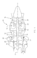
- FIG. 1 is a schematic side cross-sectional view of a gas turbine engine having variable inlet guide vanes (VIGVs);
- VIGVs variable inlet guide vanes
- FIG. 2 is a perspective view of an apparatus for actuating the VIGVs of FIG. 1 , according to one embodiment, showing a connection arm having one bolting flange at one side thereof connected to a stem of a VIGV;
- FIG. 3 is a perspective view of the apparatus of FIG. 2 , showing the other side of the connection arm being open to allow a bolting nut directly resting on the stem of the VIGV;
- FIG. 4 is a front elevational view of the connection arm according to another embodiment, connected to a stem of the VIGVs of FIG. 1 ;
- FIG. 5 is a partial and front elevational view of the connection arm according to another embodiment, connected to a stem of the VIGVs of FIG. 1 ;
- FIG. 6 is a partial and front elevational view of the connection arm of FIG. 5 , without being connected to a stem of a VIGV;
- FIG. 7 is a cross-sectional view of the connection arm, taken along line 7 - 7 of FIG. 6 ;
- FIG. 8 is a schematic front elevational view of a connection arm according to another embodiment, showing double bolting flanges for connection with the stem of a VIGV.
- FIG. 1 illustrates an example of a gas turbine engine.
- the turbine engine 10 is a turboshaft engine generally comprising in serial flow communication a compressor section 12 for pressurizing air, a combustor 14 in which the pressurized air is mixed with fuel and ignited for generating an annular stream of hot combustion gases, and a turbine section 16 for extracting energy from the combustion gases.
- the turbine engine 10 in this example can be seen to include a high pressure spool assembly 18 including a multistage compressor 19 and a high pressure turbine stage 20 , and a low pressure spool assembly 22 including a low pressure turbine stage 24 .
- the low pressure spool assembly 22 is connected to a power shaft (not numbered) via a gear arrangement.
- the high pressure spool assembly 18 can be referred to herein as a compressor spool, given that it contains at least one compressor stage, and the low pressure spool assembly 22 can be referred to herein as a power spool.
- the compressor section 12 defines an annular airflow duct 25 having a radial inlet section (not numbered) to direct an airflow radially inwardly into the annular airflow duct 25 of the compressor section 12 , as indicated by the arrows.
- a variable guide vane (VGV) apparatus 26 is mounted to the compressor section 12 and has a plurality of variable inlet guide vanes 28 (VIGVs) which are positioned and rotatably supported within the radial inlet section of the airflow duct 25 .
- the VIGV's 28 are each rotatable about a rotational axis 30 thereof, which is substantially parallel to the central axis 11 of the engine.
- the angular orientation of the VIGVs about the respective rotational axis 30 is adjustable such that the airflow entering the radial inlet section of the airflow duct 25 as indicated by the arrows, is controlled by the VIGVs 28 .
- the VIGVs 28 are connected to and the angular orientation thereof is actuated by other components of the apparatus 26 which are positioned outside of the radial inlet section of the airflow duct 25 .
- the apparatus 26 may further include a unison ring 32 defining a central axis thereof substantially superposed with the central axis 11 of the engine 10 .
- the unison ring 32 is supported in the engine 10 , for example by a support structure affixed to a casing forming the annular air duct 25 in order to allow the unison ring 32 to be adjustable in a circumferential direction with respect to the central axis 11 of the engine.
- the unison ring 32 may be disposed outside of the airflow duct 25 , for example behind the radial inlet section of the annular air duct 25 , and may have a plurality of drive pins 34 corresponding to the respective VIGVs 28 .
- Each of the drive pins 34 may be affixed to a front side (facing the VIGVs 28 ) of the unison ring 32 , and may extend substantially axially with respect to the central axis 11 of the engine 10 , from the front side of the unison ring 32 towards the VIGVs 28 . Therefore, the drive pins 34 together with the unison ring 32 are adjustable in an angular orientation about the central axis 11 .
- a connection arm 36 may be provided, which includes a base 38 , a pair of forks 40 extending in a parallel relationship and radially outwardly from the base 38 , and a bolting flange 42 extending radially inwardly from the base 38 with respect to the central axis 11 .
- the forks 40 and the base 38 may form a U-shaped profile and the bolting flange 42 may be disposed offset from a central axis 44 of the U-shaped profile.
- the bolting flange 42 may have a thickness greater than the thickness of the respective forks 40 .
- the forks 40 in combination may define a slot therebetween into which one of the axial drive pins 34 may be slidably received.
- the bolting flange 42 may define a hole 46 extending therethrough in a direction for example, substantially tangential to the central axis 11 of the engine 10 (normal to the central axis 44 of the U-shaped profile of the forks 40 /base 38 configuration as shown in FIG. 4 ).
- the apparatus 26 may further include a stem 48 connected to or integrated with each of the VIGVs 28 , and being disposed axially with respect to the central axis 11 of the engine 10 .
- the stem 48 may have a cylindrical section 50 rotatably supported in the engine to thereby define the rotational axis 30 of the respective VIGV 28 .
- the stem 48 according to one embodiment may include an end section 52 defining parallel opposed side surfaces 54 facing away one from the other.
- the end section 52 may further include a hole 56 extending therethrough between the opposed side surfaces 54 .
- the stem 48 may be axially disposed such that one of the side surfaces 54 is placed against one side of the bolting flange 42 with the hole 56 aligned with the hole 46 of the bolting flange 42 to receive a bolt 58 extending therethrough in a tangential direction with respect to the central axis 11 .
- the bolt 58 may be engaged with a nut (not numbered) to removably secure the end section 52 of the stem 48 to the connection arm 36 .
- the other side surface 54 may be in contact with the bolt assembly (an enlarged bolt head, nut or washers) but is free of contact with any part of the connection arm 36 .
- each of the drive pins 34 which is affixed on the unison ring 32 , moves together with the unison ring 32 in the circumferential direction to drive one of the connection arms 36 (which is connected with the stem 48 ) to rotate together with the stem 48 about the respective rotational axis 30 of the VIGVs 28 , resulting in adjustment of the angular orientation of the respective VIGVs 28 in order to control the airflow entering the radial inlet section of the annular air duct 25 .
- the drive pin 34 is allowed to slide along the slot defined between the two drive forks 40 when the drive pin 34 drives the connection arm 36 in rotation about the rotational axis 30 , because the circumferential movement of the drive pin 34 about the central axis 11 of the engine 10 has a rotation radius much larger than the rotation radius of the connection arm 36 about the respective rotational axis 30 of the VIGVs 28 .
- connection arm 36 may further include a support member 60 affixed to and extending from a radial end (not numbered) of the bolting flange 42 and may be spaced apart from the base 38 of the connection arm 36 .
- the base 38 and support member 60 of each connection arm 36 therefore provide a positioning and retaining function to receive the end section 52 to be retained radially therebetween when one of the side surfaces 54 of the end section 52 of the stem 48 is placed against one side of the bolting flange 42 during an assembly procedure of the apparatus 26 .
- the respective base 38 and support member 60 may have curved surfaces such as concave surfaces 62 and 64 .
- the end section 52 of the stem 48 may define a radially-outer surface 66 and a radially-inner surface 68 in a curved profile such as a convex profile which may be at least partially in contact with the concave surfaces 62 , 64 of the respective base 38 and support member 60 when the end section 52 of the stem 48 is connected to the bolting flange 42 of the connection arm 36 .
- the curved profiles of the respective connection arm 36 and the end section 52 of the stem 48 therefore provide an interlock function to further facilitate the positioning and retaining of the end section 52 of the stem 48 during an assembly procedure of the apparatus 26 without the need of manually holding the connection arm 36 in place.
- connection arm 36 may further include a back flange 70 affixed to and extending radially and inwardly from the base 38 with respect to the central axis 11 of the engine 10 .
- the back flange 70 may be disposed substantially normal to the bolting flange 42 and may be joined to the bolting flange 42 at a position adjacent the unison ring 32 , thereby forming an inner corner having a joint edge 72 extending substantially in a radial direction with respect to the center line 11 of the engine 10 .
- the bolting flange 42 and the back flange 70 in combination may provide an L-shaped configuration to allow the end section 52 of the stem 48 to be axially positioned in place by axially sliding along a side of the bolting flange 42 toward the back flange 70 , as indicated by the arrow in FIG. 7 .
- Positioning of the end section 52 of the stem 48 in place by a tangential/circumferential movement towards the bolting flange 42 is prohibited (as indicated by the crossed arrow in FIG. 6 ) due to the interlock function provided by the curved profile of the respective connection arm 36 and the end section 52 , as shown in FIG. 5 .
- the back flange 70 prevents the end section 52 of the stem 48 from over-insertion and therefore facilitates axial positioning of the stem 48 with respect to the connection arm 36 during the assembly procedure of the apparatus.
- the back flange 70 may also join with the support member 60 such that the bolting flange 42 , support member 60 , base 38 and the back flange 70 create a robust configuration defining a recess 74 therein with four sides of the recess 74 being closed and one side open to allow the end section 52 of the stem 48 to axially slide in and a second side open to expose the other side 54 of the end section 52 to be free of contact with any part of the connection arm 36 .
- connection arm 36 may be formed as an integral single-piece component, including the forks 40 , base 38 , bolting flange 42 and the support member 60 , and may further include the back flange 70 .
- connection arm 36 may have first and second bolting flanges 42 a and 42 b to define a slot 76 therebetween in order to receive the end section 52 of the stem 48 (see FIGS. 3 and 5 ).
- a bolt/nut assembly (not shown) which fastens the end section 52 of the stem 48 between the first and second bolting flanges 42 a , 42 b , applies a clamping action on the two bolting flanges 42 a , 42 b to urge the two bolting flanges 42 a and 42 b towards each other, as indicated by arrows 78 .
- the clamping action as indicated by arrows 78 may cause distortion of the connection arm 36 such that the pair of forks 40 move slightly away from each other, as indicated by arrows 80 , resulting in an increased width of the slot 77 defined between the pair of forks 40 .
- This increased width may cause a loose contact of the drive pin 34 with the pair of forks 40 and may impact the accurate adjustment of the angular orientation of the respective VIGVs 28 . Therefore, machining of the stems 48 of the VIGVs 28 and the connection arms 36 may require high accuracy with very restricted tolerances.
- the embodiments described with reference to FIGS. 2-7 have only a single bolting flange 42 and the clamping action created by the bolt/nut assembly is transferred to the opposite sides of the single bolting flange 42 which will create no distortion of the connection arm 36 . Therefore, tolerance relaxation in the machining process of the arms and stems can be achieved without compromising accurate adjustment of the VIGV's angular orientation.
- the actuating apparatus can be applicable in a variable guide vane (VGV) system which can be disposed in any location of an air duct, not limited to an inlet section thereof.
- VGV variable guide vane
- the actuating apparatus described above is also applicable when connected to an axial VGV system with guide vanes positioned substantially perpendicular (radially) to the central axis of the engine.
- the drive pin affixed to the unison ring and the stem connected to the VGV, extend radially (perpendicular to the central axis of the engine). Therefore, the drive pin drives the arm (which is disposed axially) to rotate together with the stem about a radial rotational axis of the stem.
Landscapes
- Engineering & Computer Science (AREA)
- Mechanical Engineering (AREA)
- General Engineering & Computer Science (AREA)
- Chemical & Material Sciences (AREA)
- Combustion & Propulsion (AREA)
- Physics & Mathematics (AREA)
- Fluid Mechanics (AREA)
- Structures Of Non-Positive Displacement Pumps (AREA)
Priority Applications (2)
| Application Number | Priority Date | Filing Date | Title |
|---|---|---|---|
| US14/304,134 US9644491B2 (en) | 2014-06-13 | 2014-06-13 | Single bolting flange arrangement for variable guide vane connection |
| CA2894032A CA2894032C (fr) | 2014-06-13 | 2015-06-08 | Ensemble bride a boulonnage simple pour raccordement d'aube guide variable |
Applications Claiming Priority (1)
| Application Number | Priority Date | Filing Date | Title |
|---|---|---|---|
| US14/304,134 US9644491B2 (en) | 2014-06-13 | 2014-06-13 | Single bolting flange arrangement for variable guide vane connection |
Publications (2)
| Publication Number | Publication Date |
|---|---|
| US20150361820A1 US20150361820A1 (en) | 2015-12-17 |
| US9644491B2 true US9644491B2 (en) | 2017-05-09 |
Family
ID=54835745
Family Applications (1)
| Application Number | Title | Priority Date | Filing Date |
|---|---|---|---|
| US14/304,134 Active 2035-07-10 US9644491B2 (en) | 2014-06-13 | 2014-06-13 | Single bolting flange arrangement for variable guide vane connection |
Country Status (2)
| Country | Link |
|---|---|
| US (1) | US9644491B2 (fr) |
| CA (1) | CA2894032C (fr) |
Cited By (3)
| Publication number | Priority date | Publication date | Assignee | Title |
|---|---|---|---|---|
| US11092032B2 (en) * | 2018-08-28 | 2021-08-17 | Pratt & Whitney Canada Corp. | Variable vane actuating system |
| US11092167B2 (en) * | 2018-08-28 | 2021-08-17 | Pratt & Whitney Canada Corp. | Variable vane actuating system |
| US11371380B2 (en) | 2020-12-01 | 2022-06-28 | Pratt & Whitney Canada Corp. | Variable guide vane assembly and vane arms therefor |
Families Citing this family (3)
| Publication number | Priority date | Publication date | Assignee | Title |
|---|---|---|---|---|
| DE102016224523A1 (de) | 2016-12-08 | 2018-06-14 | MTU Aero Engines AG | Leitschaufelverstellung mit seitlich montiertem Verstellhebel |
| JP7020396B2 (ja) * | 2018-12-27 | 2022-02-16 | 株式会社豊田自動織機 | ターボチャージャに用いられるリンク機構 |
| CN117189681A (zh) * | 2023-10-09 | 2023-12-08 | 中国科学院工程热物理研究所 | 一种用于驱动可调导叶的驱动机构 |
Citations (20)
| Publication number | Priority date | Publication date | Assignee | Title |
|---|---|---|---|---|
| US3685920A (en) | 1971-02-01 | 1972-08-22 | Gen Electric | Actuation ring for variable geometry compressors or gas turbine engines |
| US3982390A (en) * | 1974-08-22 | 1976-09-28 | General Motors Corporation | Gas turbine engine cooling system |
| US4035101A (en) * | 1976-03-24 | 1977-07-12 | Westinghouse Electric Corporation | Gas turbine nozzle vane adjusting mechanism |
| US4049360A (en) | 1975-05-01 | 1977-09-20 | Rolls-Royce (1971) Limited | Variable stator vane actuating mechanism |
| US4430043A (en) | 1980-06-28 | 1984-02-07 | Rolls-Royce Limited | Variable stator vane operating mechanism for turbomachines |
| US4773821A (en) | 1986-12-17 | 1988-09-27 | Societe Nationale D'etude Et De Construction De Moteurs D'aviation "S.N.E.C.M.A." | Control mechanism for variably settable vanes of a flow straightener in a turbine plant |
| US4826399A (en) | 1988-05-06 | 1989-05-02 | General Motors Corporation | Unison ring mounting arrangement |
| US5061152A (en) | 1989-03-15 | 1991-10-29 | Societe Nationale D'etude Et De Construction De Moteurs D'aviation | Mounting for variably settable stator blades in a compressor |
| US5096374A (en) | 1989-02-02 | 1992-03-17 | Hitachi, Ltd. | Vane controller |
| US5492446A (en) | 1994-12-15 | 1996-02-20 | General Electric Company | Self-aligning variable stator vane |
| US6699010B2 (en) | 2000-05-19 | 2004-03-02 | Mitsubishi Heavy Industries, Ltd. | Nozzle adjustment mechanism for variable-capacity turbine |
| US7004723B2 (en) | 2003-04-16 | 2006-02-28 | Snecma Moteurs | Device for controlling variable-pitch vanes in a turbomachine |
| US7011494B2 (en) | 2004-02-04 | 2006-03-14 | United Technologies Corporation | Dual retention vane arm |
| US7140838B2 (en) | 2003-05-07 | 2006-11-28 | Snecma Moteurs | Control lever attachment with play compensation for blades with variable setting angles |
| US7300245B2 (en) | 2004-12-16 | 2007-11-27 | Snecma | Stator vane stage actuated by an automatically-centering rotary actuator ring |
| US7938620B2 (en) | 2006-06-16 | 2011-05-10 | Snecma | Turbomachine stator including a stage of stator vanes actuated by an automatically centered rotary ring |
| FR2904669B1 (fr) * | 2006-08-02 | 2012-05-18 | Snecma | Dispositif de commande d'aube a angle de calage variable de turbomachine |
| US8215902B2 (en) | 2008-10-15 | 2012-07-10 | United Technologies Corporation | Scalable high pressure compressor variable vane actuation arm |
| US8226357B2 (en) | 2007-10-12 | 2012-07-24 | Snecma | Pitch control ring for stator vanes of a turbomachine |
| US9200640B2 (en) * | 2009-11-03 | 2015-12-01 | Ingersoll-Rand Company | Inlet guide vane for a compressor |
-
2014
- 2014-06-13 US US14/304,134 patent/US9644491B2/en active Active
-
2015
- 2015-06-08 CA CA2894032A patent/CA2894032C/fr active Active
Patent Citations (21)
| Publication number | Priority date | Publication date | Assignee | Title |
|---|---|---|---|---|
| US3685920A (en) | 1971-02-01 | 1972-08-22 | Gen Electric | Actuation ring for variable geometry compressors or gas turbine engines |
| US3982390A (en) * | 1974-08-22 | 1976-09-28 | General Motors Corporation | Gas turbine engine cooling system |
| US4049360A (en) | 1975-05-01 | 1977-09-20 | Rolls-Royce (1971) Limited | Variable stator vane actuating mechanism |
| US4035101A (en) * | 1976-03-24 | 1977-07-12 | Westinghouse Electric Corporation | Gas turbine nozzle vane adjusting mechanism |
| US4430043A (en) | 1980-06-28 | 1984-02-07 | Rolls-Royce Limited | Variable stator vane operating mechanism for turbomachines |
| US4773821A (en) | 1986-12-17 | 1988-09-27 | Societe Nationale D'etude Et De Construction De Moteurs D'aviation "S.N.E.C.M.A." | Control mechanism for variably settable vanes of a flow straightener in a turbine plant |
| US4826399A (en) | 1988-05-06 | 1989-05-02 | General Motors Corporation | Unison ring mounting arrangement |
| US5096374A (en) | 1989-02-02 | 1992-03-17 | Hitachi, Ltd. | Vane controller |
| US5061152A (en) | 1989-03-15 | 1991-10-29 | Societe Nationale D'etude Et De Construction De Moteurs D'aviation | Mounting for variably settable stator blades in a compressor |
| US5492446A (en) | 1994-12-15 | 1996-02-20 | General Electric Company | Self-aligning variable stator vane |
| US6699010B2 (en) | 2000-05-19 | 2004-03-02 | Mitsubishi Heavy Industries, Ltd. | Nozzle adjustment mechanism for variable-capacity turbine |
| US7004723B2 (en) | 2003-04-16 | 2006-02-28 | Snecma Moteurs | Device for controlling variable-pitch vanes in a turbomachine |
| US7140838B2 (en) | 2003-05-07 | 2006-11-28 | Snecma Moteurs | Control lever attachment with play compensation for blades with variable setting angles |
| US7011494B2 (en) | 2004-02-04 | 2006-03-14 | United Technologies Corporation | Dual retention vane arm |
| US7300245B2 (en) | 2004-12-16 | 2007-11-27 | Snecma | Stator vane stage actuated by an automatically-centering rotary actuator ring |
| USRE42523E1 (en) | 2004-12-16 | 2011-07-05 | Snecma | Stator vane stage actuated by an automatically-centering rotary actuator ring |
| US7938620B2 (en) | 2006-06-16 | 2011-05-10 | Snecma | Turbomachine stator including a stage of stator vanes actuated by an automatically centered rotary ring |
| FR2904669B1 (fr) * | 2006-08-02 | 2012-05-18 | Snecma | Dispositif de commande d'aube a angle de calage variable de turbomachine |
| US8226357B2 (en) | 2007-10-12 | 2012-07-24 | Snecma | Pitch control ring for stator vanes of a turbomachine |
| US8215902B2 (en) | 2008-10-15 | 2012-07-10 | United Technologies Corporation | Scalable high pressure compressor variable vane actuation arm |
| US9200640B2 (en) * | 2009-11-03 | 2015-12-01 | Ingersoll-Rand Company | Inlet guide vane for a compressor |
Non-Patent Citations (1)
| Title |
|---|
| Hinds, Paul. "Joinery Terms" accessed from http://www.hobbithouseinc.com/personal/woodpics/—joineryterms.htm on Aug. 22, 2016 available as of Jun. 4, 2013 via archive.org. * |
Cited By (3)
| Publication number | Priority date | Publication date | Assignee | Title |
|---|---|---|---|---|
| US11092032B2 (en) * | 2018-08-28 | 2021-08-17 | Pratt & Whitney Canada Corp. | Variable vane actuating system |
| US11092167B2 (en) * | 2018-08-28 | 2021-08-17 | Pratt & Whitney Canada Corp. | Variable vane actuating system |
| US11371380B2 (en) | 2020-12-01 | 2022-06-28 | Pratt & Whitney Canada Corp. | Variable guide vane assembly and vane arms therefor |
Also Published As
| Publication number | Publication date |
|---|---|
| CA2894032A1 (fr) | 2015-12-13 |
| US20150361820A1 (en) | 2015-12-17 |
| CA2894032C (fr) | 2022-08-30 |
Similar Documents
| Publication | Publication Date | Title |
|---|---|---|
| CA2894032C (fr) | Ensemble bride a boulonnage simple pour raccordement d'aube guide variable | |
| CN106286390B (zh) | 用于涡轮发动机的耳轴保持件 | |
| US10094223B2 (en) | Integrated strut and IGV configuration | |
| US7104754B2 (en) | Variable vane arrangement for a turbomachine | |
| US9494045B2 (en) | Exhaust-gas turbocharger | |
| US6951112B2 (en) | Methods and apparatus for assembling gas turbine engines | |
| US9890656B2 (en) | Variable stator vane arrangement | |
| US10436151B2 (en) | Modular fan for a gas turbine engine | |
| GB2525319A (en) | A device for locking a nut | |
| WO2013146590A1 (fr) | Segment d'aube de stator et machine à fluide à flux axial le comportant | |
| US8764387B2 (en) | Aggregate vane assembly | |
| US20220372890A1 (en) | Actuation system with spherical plain bearing | |
| US10443451B2 (en) | Shroud housing supported by vane segments | |
| KR102027199B1 (ko) | 가변 베인 구동장치 및 이를 포함하는 가스터빈 | |
| EP3722564B1 (fr) | Agencement de levier d'aube directrice pour moteur à turbine à gaz, procéde de rétention axiale redondante d'un levier d'aube directrice et moteur à turbine à gaz associés | |
| US10794200B2 (en) | Integral half vane, ringcase, and id shroud | |
| EP3219931B1 (fr) | Agencement d'aube distributrice et moteur à turbine à gaz associé | |
| US20160177835A1 (en) | Gas turbine engine with angularly offset turbine vanes | |
| EP3018301B1 (fr) | Bras d'aube à fente de rétention inclinée | |
| US11371352B2 (en) | Device for holding a centripetal radial air sampling member | |
| US11988229B2 (en) | Diffuser pipe alignment tool | |
| CN108661727B (zh) | 涡轮发动机轴承组件及其组装方法 | |
| EP3650637B1 (fr) | Étage statorique d'une tubine à gaz avec demi-aubes monobloc avec un carter extérieur et une virole interne | |
| US10781707B2 (en) | Integral half vane, ringcase, and id shroud | |
| US20050172638A1 (en) | Methods and apparatus for assembling gas turbine engines |
Legal Events
| Date | Code | Title | Description |
|---|---|---|---|
| AS | Assignment |
Owner name: PRATT & WHITNEY CANADA CORP., CANADA Free format text: ASSIGNMENT OF ASSIGNORS INTEREST;ASSIGNORS:ZHOU, YONGSHENG;URAC, TIBOR;LEUNG, ESTHER;AND OTHERS;SIGNING DATES FROM 20140618 TO 20140702;REEL/FRAME:033272/0545 |
|
| STCF | Information on status: patent grant |
Free format text: PATENTED CASE |
|
| MAFP | Maintenance fee payment |
Free format text: PAYMENT OF MAINTENANCE FEE, 4TH YEAR, LARGE ENTITY (ORIGINAL EVENT CODE: M1551); ENTITY STATUS OF PATENT OWNER: LARGE ENTITY Year of fee payment: 4 |
|
| MAFP | Maintenance fee payment |
Free format text: PAYMENT OF MAINTENANCE FEE, 8TH YEAR, LARGE ENTITY (ORIGINAL EVENT CODE: M1552); ENTITY STATUS OF PATENT OWNER: LARGE ENTITY Year of fee payment: 8 |