US9719905B2 - Methods of measuring electrode density and electrode porosity - Google Patents
Methods of measuring electrode density and electrode porosity Download PDFInfo
- Publication number
- US9719905B2 US9719905B2 US14/331,510 US201414331510A US9719905B2 US 9719905 B2 US9719905 B2 US 9719905B2 US 201414331510 A US201414331510 A US 201414331510A US 9719905 B2 US9719905 B2 US 9719905B2
- Authority
- US
- United States
- Prior art keywords
- electrode
- peak
- active material
- electrode active
- density
- Prior art date
- Legal status (The legal status is an assumption and is not a legal conclusion. Google has not performed a legal analysis and makes no representation as to the accuracy of the status listed.)
- Active, expires
Links
Images


Classifications
-
- G—PHYSICS
- G01—MEASURING; TESTING
- G01N—INVESTIGATING OR ANALYSING MATERIALS BY DETERMINING THEIR CHEMICAL OR PHYSICAL PROPERTIES
- G01N23/00—Investigating or analysing materials by the use of wave or particle radiation, e.g. X-rays or neutrons, not covered by groups G01N3/00 – G01N17/00, G01N21/00 or G01N22/00
- G01N23/20—Investigating or analysing materials by the use of wave or particle radiation, e.g. X-rays or neutrons, not covered by groups G01N3/00 – G01N17/00, G01N21/00 or G01N22/00 by using diffraction of the radiation by the materials, e.g. for investigating crystal structure; by using scattering of the radiation by the materials, e.g. for investigating non-crystalline materials; by using reflection of the radiation by the materials
-
- G—PHYSICS
- G01—MEASURING; TESTING
- G01N—INVESTIGATING OR ANALYSING MATERIALS BY DETERMINING THEIR CHEMICAL OR PHYSICAL PROPERTIES
- G01N9/00—Investigating density or specific gravity of materials; Analysing materials by determining density or specific gravity
- G01N9/36—Analysing materials by measuring the density or specific gravity, e.g. determining quantity of moisture
-
- G—PHYSICS
- G01—MEASURING; TESTING
- G01N—INVESTIGATING OR ANALYSING MATERIALS BY DETERMINING THEIR CHEMICAL OR PHYSICAL PROPERTIES
- G01N23/00—Investigating or analysing materials by the use of wave or particle radiation, e.g. X-rays or neutrons, not covered by groups G01N3/00 – G01N17/00, G01N21/00 or G01N22/00
- G01N23/20—Investigating or analysing materials by the use of wave or particle radiation, e.g. X-rays or neutrons, not covered by groups G01N3/00 – G01N17/00, G01N21/00 or G01N22/00 by using diffraction of the radiation by the materials, e.g. for investigating crystal structure; by using scattering of the radiation by the materials, e.g. for investigating non-crystalline materials; by using reflection of the radiation by the materials
- G01N23/207—Diffractometry using detectors, e.g. using a probe in a central position and one or more displaceable detectors in circumferential positions
-
- G—PHYSICS
- G01—MEASURING; TESTING
- G01N—INVESTIGATING OR ANALYSING MATERIALS BY DETERMINING THEIR CHEMICAL OR PHYSICAL PROPERTIES
- G01N25/00—Investigating or analyzing materials by the use of thermal means
- G01N25/20—Investigating or analyzing materials by the use of thermal means by investigating the development of heat, i.e. calorimetry, e.g. by measuring specific heat, by measuring thermal conductivity
-
- H—ELECTRICITY
- H01—ELECTRIC ELEMENTS
- H01M—PROCESSES OR MEANS, e.g. BATTERIES, FOR THE DIRECT CONVERSION OF CHEMICAL ENERGY INTO ELECTRICAL ENERGY
- H01M4/00—Electrodes
-
- G—PHYSICS
- G01—MEASURING; TESTING
- G01N—INVESTIGATING OR ANALYSING MATERIALS BY DETERMINING THEIR CHEMICAL OR PHYSICAL PROPERTIES
- G01N2223/00—Investigating materials by wave or particle radiation
- G01N2223/60—Specific applications or type of materials
- G01N2223/633—Specific applications or type of materials thickness, density, surface weight (unit area)
-
- G—PHYSICS
- G01—MEASURING; TESTING
- G01N—INVESTIGATING OR ANALYSING MATERIALS BY DETERMINING THEIR CHEMICAL OR PHYSICAL PROPERTIES
- G01N2223/00—Investigating materials by wave or particle radiation
- G01N2223/60—Specific applications or type of materials
- G01N2223/649—Specific applications or type of materials porosity
-
- H—ELECTRICITY
- H01—ELECTRIC ELEMENTS
- H01M—PROCESSES OR MEANS, e.g. BATTERIES, FOR THE DIRECT CONVERSION OF CHEMICAL ENERGY INTO ELECTRICAL ENERGY
- H01M4/00—Electrodes
- H01M4/02—Electrodes composed of, or comprising, active material
- H01M2004/021—Physical characteristics, e.g. porosity, surface area
-
- H—ELECTRICITY
- H01—ELECTRIC ELEMENTS
- H01M—PROCESSES OR MEANS, e.g. BATTERIES, FOR THE DIRECT CONVERSION OF CHEMICAL ENERGY INTO ELECTRICAL ENERGY
- H01M4/00—Electrodes
- H01M4/02—Electrodes composed of, or comprising, active material
- H01M4/13—Electrodes for accumulators with non-aqueous electrolyte, e.g. for lithium-accumulators; Processes of manufacture thereof
-
- Y—GENERAL TAGGING OF NEW TECHNOLOGICAL DEVELOPMENTS; GENERAL TAGGING OF CROSS-SECTIONAL TECHNOLOGIES SPANNING OVER SEVERAL SECTIONS OF THE IPC; TECHNICAL SUBJECTS COVERED BY FORMER USPC CROSS-REFERENCE ART COLLECTIONS [XRACs] AND DIGESTS
- Y02—TECHNOLOGIES OR APPLICATIONS FOR MITIGATION OR ADAPTATION AGAINST CLIMATE CHANGE
- Y02E—REDUCTION OF GREENHOUSE GAS [GHG] EMISSIONS, RELATED TO ENERGY GENERATION, TRANSMISSION OR DISTRIBUTION
- Y02E60/00—Enabling technologies; Technologies with a potential or indirect contribution to GHG emissions mitigation
- Y02E60/10—Energy storage using batteries
Definitions
- the present invention relates to methods of measuring electrode density and electrode porosity using X-ray diffraction.
- an electrode density or electrode porosity of electrodes used in a lithium secondary battery is obtained in a state in which a slurry is prepared by mixing a cathode or anode active material with a solvent, if necessary, a binder and a conductive agent and stirring, an electrode base material of a cathode or anode formed of a metallic material is coated therewith and dried, and the dried electrode based material is then pressed at an appropriate pressure.
- the electrode density is increased while the porosity decreases as the applied pressure increases.
- the electrode density and electrode porosity may be related to various battery characteristics including energy density of the battery, electrical conductivity of the electrode, and ionic conductivity.
- appropriate electrode density and electrode porosity may be different from desired battery characteristics, and it is very important to minimize the deviation thereof in a production process of the electrode.
- a method of measuring an electrode density (D) is performed in such a manner that weight and thickness of an electrode are measured by sampling a specific area of the electrode when needed, and the density is measured using a value in which mass and thickness of an electrode base material, i.e., a metal such as copper or aluminum, having the same area are subtracted from the respective measured values.
- the electrode density obtained by sampling the specific area of the electrode is subtracted from 1 to obtain a value
- an electrode porosity (P) is obtained by dividing the value by the density of the electrode excluding the electrode base material and then calculating in terms of percentage.
- the measurements of the electrode density and the electrode porosity by the above methods may have the following limitations. First, since an electrode must be sampled whenever density and porosity of each electrode are needed, a portion of the electrode must be destructed for each measurement. Thus, it may be time consuming as well as cost consuming. Also, since an electrode base material must be dissolved in a predetermined solvent to measure the density and thickness of the electrode excluding the electrode base material, a measurement process may be complicated.
- the present invention provides a method of efficiently measuring electrode density and porosity by a non-destructive method using X-ray diffraction.
- a method of measuring an electrode density including obtaining an I peak in parallel direction /I peak in perpendicular direction value of an electrode active material, on which a density is to be measured, by X-ray diffraction; and calculating a targeted electrode density according to a correlation between the electrode density and the I peak in parallel direction /I peak in perpendicular direction value of the electrode active material which are obtained in advance.
- a method of measuring an electrode porosity including 1) obtaining an I peak in parallel direction /I peak in perpendicular direction value of an electrode active material, on which a porosity is to be measured, by X-ray diffraction; and 2) calculating a targeted electrode porosity according to a correlation between the electrode porosity and the I peak in parallel direction /I peak in perpendicular direction value of the electrode active material which are obtained in advance.
- electrode density and electrode porosity may be efficiently measured by a non-destructive method using X-ray diffraction.
- FIG. 1 a illustrates a structure of an electrode active material coated on an electrode
- FIG. 1 b illustrates the principle of X-ray diffraction
- FIG. 1 c is a graph illustrating peaks of the electrode active material (e.g., graphite) coated on the electrode which are obtained by X-ray diffraction;
- FIG. 2 a is a graph illustrating peaks obtained by X-ray diffraction when an electrode active material is arranged parallel to a base plane of an electrode according to an embodiment of the present invention
- FIG. 2 b is a graph illustrating peaks obtained by X-ray diffraction when an electrode active material is arranged perpendicular to the base plane of the electrode;
- FIG. 3 is a graph illustrating a correlation between electrode density and I 004 /I 110 according to an embodiment of the present invention.
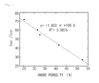
- FIG. 4 is a graph illustrating a correlation between electrode porosity and I 004 /I 110 according to an embodiment of the present invention.
- a method of measuring an electrode density may include 1) obtaining an I peak in parallel direction /I peak in perpendicular direction value of an electrode active material, on which a density is to be measured, by X-ray diffraction; and 2) calculating a targeted electrode density according to a correlation between the electrode density and the I peak in parallel direction /I peak in perpendicular direction value of the electrode active material which are obtained in advance.
- a method of measuring an electrode porosity may include 1) obtaining an I peak in parallel direction /I peak in perpendicular direction value of an electrode active material, on which a porosity is to be measured, by X-ray diffraction; and 2) calculating a targeted electrode porosity according to a correlation between the electrode porosity and the I peak in parallel direction /I peak in perpendicular direction value of the electrode active material which are obtained in advance.
- the methods of measuring electrode density and electrode porosity of the present invention use X-ray diffraction, there is no need to destruct a portion of the electrode for each measurement.
- the electrode density and electrode porosity may be measured simply and efficiently in terms of effort and time as well as cost.
- FIG. 1 ( FIGS. 1 a to 1 c ) illustrates an X-ray diffraction measurement method of an electrode according to an embodiment of the present invention.
- FIG. 1 a illustrates a structure of an electrode active material coated on an electrode
- FIG. 1 b illustrates the principle of X-ray diffraction
- FIG. 1 c illustrates peaks of the electrode active material coated on the electrode which are obtained by X-ray diffraction.
- the electrode coated with the electrode active material as in FIG. 1 is irradiate with X-ray to obtain relative intensities of diffraction peaks according to an incident angle, and electrode density and electrode porosity may be measured using the relative intensities.
- the electrode active material may include a carbon-based active material.
- the electrode coated with graphite having the above crystal structure may be irradiated with X-ray as illustrated in FIG. 1 b , and the principle thereof is as follows. That is, in a case where atoms in the graphite coated on the electrode are arranged on parallel lattice planes A, B, and C having spacing d, X-ray is scattered in all directions by the atoms when the X-ray with wavelength ⁇ is incident on the crystal at incident angle ⁇ . If P′RP′′ of the scattered X-ray is an integer multiple of the wavelength of the incident X-ray, the X-ray is intensified due to interference effects, and this phenomenon is referred to as a diffraction phenomenon.
- FIG. 1 c illustrates peaks obtained by X-ray diffraction as in FIG. 1 b , wherein a plurality of diffraction peaks having different intensities are presented when X-ray diffraction intensities are recorded while continuously changing the angle of X-ray incident on the electrode coated with a graphite-based electrode active material, and for example, 004 peak and 110 peak may be obtained.
- type and intensity of peaks of the electrode active material coated on the electrode obtained by X-ray diffraction may be different according to its orientation, and an example thereof is illustrated in FIG. 2 .
- diffraction peaks such as 002, 004, and 006 peaks, may only be observed.
- an electrode density or electrode porosity of electrodes used in a lithium secondary battery is obtained by coating an electrode base material with a slurry including an electrode active material, drying a solvent, and pressing the dried electrode based material at an appropriate pressure.
- the electrode density is increased while the porosity decreases as the applied pressure increases.
- the electrode density is in a high correlation with a value obtained by dividing an area (I peak in parallel direction ) of the peak in a parallel direction of the electrode active material illustrated in FIG. 2 a that is arranged parallel to the base plane of the electrode by an area (I peak in perpendicular direction ) of the peak in a perpendicular direction of the electrode active material illustrated in FIG. 2 b that is arranged perpendicular to the base plane of the electrode, i.e., I peak in parallel direction /I peak in perpendicular direction .
- the correlation between the electrode density and the I peak in parallel direction /I peak in perpendicular direction of the electrode active material may be a linear relationship with a high coefficient of determination.
- the electrode porosity is in a high correlation with a value obtained by dividing an area (I peak in parallel direction ) of the peak in a parallel direction of the electrode active material illustrated in FIG. 2 a that is arranged parallel to the base plane of the electrode by an area (I peak in perpendicular direction ) of the peak in a perpendicular direction of the electrode active material illustrated in FIG. 2 b that is arranged perpendicular to the base plane of the electrode, i.e., I peak in parallel direction /I peak in perpendicular direction .
- the correlation between the electrode porosity and the I peak in parallel direction /I peak in perpendicular direction of the electrode active material may be a linear relationship with a high coefficient of determination.
- coefficient of determination used in the present invention denotes a coefficient of measuring whether a regression line estimated by sample observation explains an actually observed sample to some extent, that is, whether the regression line represents an actual observed value to some extent to show the goodness of fit, and may be defined as a value representing a correlation between X value and Y value.
- the coefficient of determination is represented as R 2 and is the same as the square of a correlation coefficient (R).
- R 2 is a value between 0 and 1, wherein the larger the R 2 value is, the higher the correlation is.
- the estimated regression line fully explains the relationship between variables.
- correlation coefficient used in the present invention may be a statistical quantity for measuring the degree of a linear relationship between two variables, and may be defined as a numerical measure for measuring the strength of a linear relationship indicating how close points are scattered around a straight line.
- the correlation coefficient is represented as “R”, and R always has a value between ⁇ 1 and 1.
- R when R>0, x and y may be in a positive correlation, and this is a case in which when one variable increases, the other variable tends to increase.
- R ⁇ 0, x and y may be in a negative correlation, and this is a case in which when one variable increases, the other variable tends to decrease.
- R the larger the absolute value of R is, the higher the linear relationship between x and y may be.
- R is +1 or ⁇ 1, it is a case in which all measured values are perfectly located on the straight line.
- electrode density and electrode porosity may be measured by the above-described principle.
- step 1) is obtaining an I peak in parallel direction /I peak in perpendicular direction value of an electrode active material using X-ray diffraction of an electrode including the electrode active material, which is to be measured.
- an area (I peak in parallel direction ) of a peak in a parallel direction of an electrode active material that is arranged parallel to the base plane of the electrode and an area (I peak in perpendicular direction ) of a peak in a perpendicular direction of the electrode active material that is arranged perpendicular to the base plane of the electrode are obtained using X-ray diffraction of each electrode, and thus, a value obtained by dividing I peak in parallel direction by I peak in perpendicular direction , i.e., I peak in parallel direction /I peak in perpendicular direction , may be obtained.
- step 2) may include calculating a targeted electrode density according to a previously obtained correlation between the electrode density and the I peak in parallel direction /I peak in perpendicular direction value of the electrode active material which are obtained in advance.
- the correlation between the electrode density and the I peak in parallel direction /I peak in perpendicular direction value of the electrode active material, which are obtained in advance in step 2), may be obtained in such a manner that (a) densities of at least 3 or more electrodes including the same electrode active material are obtained according to a typical method, (b) an I peak in parallel direction /I peak in perpendicular direction value of the electrode active material of the corresponding electrode is obtained using X-ray diffraction, and the correlation between the electrode density and the I peak in parallel direction /I peak in perpendicular direction value is analyzed using the data obtained from (a) and (b).
- step 1) is obtaining an I peak in parallel direction /I peak in perpendicular direction value of an electrode active material using X-ray diffraction of an electrode including the electrode active material, which is to be measured.
- the I peak in parallel direction /I peak in perpendicular direction value of the electrode active material may be obtained in the same manner as in step 1).
- step 2) may include calculating a targeted electrode porosity according to a previously obtained correlation between the electrode porosity and the value of I peak in parallel direction /I peak in perpendicular direction of the electrode active material which are obtained in advance.
- the correlation between the electrode porosity and the I peak in parallel direction /I peak in perpendicular direction value of the electrode active material may be obtained in such a manner that (a) porosities of at least 3 or more electrodes including the same electrode active material are obtained according to a typical method, (b) an I peak in parallel direction /I peak in perpendicular direction value of the electrode active material of the corresponding electrode is obtained using X-ray diffraction, and the correlation between the electrode porosity and the I peak in parallel direction /I peak in perpendicular direction value is analyzed using the data obtained from (a) and (b).
- the I peak in parallel direction /I peak in perpendicular direction may be I 002 /I 100 , I 002 /I 110 , I 004 /I 100 , I 004 /I 110 , I 006 /I 100 , or I 006 /I 110 .
- a method typically used in the art may be used as the typical method of measuring electrode density (D) and electrode porosity (P), but the present invention is not limited thereto.
- the electrode density (D) for obtaining the correlation may be calculated from the following Equation 2
- the electrode porosity (P) may be calculated from the following Equation 3.
- D M /( S ⁇ H ) ⁇ Equation 2>
- S is an electrode area
- M is a mass of an electrode active material excluding an electrode base material in an electrode
- H represents a thickness of the electrode active material excluding the electrode base material in the electrode.
- P represents an electrode porosity
- D represents an electrode density
- T represents a true density of an electrode active material excluding an electrode base material in an electrode.
- the true density denotes an inherent density of an electrode active material without pores.
- electrode density and electrode porosity may be efficiently and simply measured using X-ray diffraction.
- the electrode base material and the electrode active material used in the electrode may be a cathode base material, an anode base material, a cathode active material, or an anode active material, which are typically used in the art.
- non-limiting examples of the cathode base material may be aluminum, nickel, or a foil prepared by a combination thereof
- non-limiting examples of the anode base material may be copper, gold, nickel, or a copper alloy, or a foil prepared by a combination thereof.
- the cathode active material may include a manganese-based spinel active material, lithium metal oxide, or a mixture thereof.
- a carbon-based anode active material such as crystalline carbon, amorphous carbon, or a carbon composite
- a carbon-based anode active material such as crystalline carbon, amorphous carbon, or a carbon composite
- Graphite-based carbon such as natural graphite and artificial graphite, may be used as the crystalline carbon.
- graphite as a carbon-based active material is described in detail as an example.
- the present invention is not limited thereto, and both cathode and anode active materials typically used in the art may be variously used.
- a coefficient of determination (R 2 ) of the electrode density obtained from the correlation is in a range of 0.6 to 1.0, may be in a range of 0.8 to 1.0, and for example, may be in a range of 0.9 to 1.0.
- a coefficient of determination (R 2 ) of the electrode porosity obtained from the correlation is in a range of 0.6 to 1.0, may be in a range of 0.8 to 1.0, and for example, may be in a range of 0.9 to 1.0.
- the coefficients of determination (R 2 ) of the electrode density and the electrode porosity are outside the above range, error ranges of the targeted electrode density and the electrode porosity may be increased, and thus, reliability may decrease.
- electrode density and electrode porosity may be efficiently measured by a non-destructive method using X-ray diffraction according to the embodiments of the present invention, and values of the electrode density and electrode porosity obtained by the above methods have considerably high accuracy.
- An anode mixture slurry was prepare by adding 96 wt % of graphite as an anode active material, 1 wt % of carboxymethyl cellulose (CMC) and 2 wt % of a styrene-butadiene rubber (SBR) as a binder, and 1 wt % of carbon black as a conductive agent to water as a solvent.
- CMC carboxymethyl cellulose
- SBR styrene-butadiene rubber
- An anode was prepared in the same manner as in Preparation Example 1 except that a thickness of the anode was 54.2 ⁇ m.
- An anode was prepared in the same manner as in Preparation Example 1 except that a thickness of the anode was 49.8 ⁇ m.
- An anode was prepared in the same manner as in Preparation Example 1 except that a thickness of the anode was 49.1 ⁇ m.
- An anode was prepared in the same manner as in Preparation Example 1 except that a thickness of the anode was 47.0 ⁇ m.
- An anode was prepared in the same manner as in Preparation Example 1 except that a thickness of the anode was 52.0 ⁇ m.
- An anode was prepared in the same manner as in Preparation Example 1 except that a thickness of the anode was 48.5 ⁇ m.
- the areas of the sampled anodes were the same for all samples, namely 1.4875 cm 2 , and the anode thickness included the thickness (21.2 ⁇ m) of copper.
- I 004 /I 110 of the anode active materials were obtained from the anodes prepared in Preparation Examples 1 to 5 by X-ray diffraction, and the results thereof are presented in Table 2 below:
- Densities of the anodes prepared in Preparation Examples 6 and 7 may be obtained by substituting the I 004 /I 110 values of the graphite active materials obtained using X-ray diffraction in 2) into the correlation, i.e., the graph of FIG. 3 , and the results thereof are presented in Table 4 below.
- the anode porosities and the I 004 /I 110 of the anode active materials obtained from the anodes prepared in Preparation Examples 1 to 5 exhibited a linear relationship with a high coefficient of determination.
- R 2 0.9875 and thus, it may be confirmed that R 2 was a value close to 1. This indicates that most of the measured porosity values of the anodes were located on a regression line and had a very high correlation.
- Porosities (%) of the anodes prepared in Preparation Examples 6 and 7 may be obtained by substituting the I 004 /I 110 values of the graphite active materials obtained using X-ray diffraction in 2) into the graph of FIG. 4 , and the results thereof are presented in Table 7 below.
- electrode density and porosity may be efficiently measured by a non-destructive method using X-ray diffraction while reducing errors.
Landscapes
- Chemical & Material Sciences (AREA)
- General Physics & Mathematics (AREA)
- Pathology (AREA)
- Health & Medical Sciences (AREA)
- Life Sciences & Earth Sciences (AREA)
- Analytical Chemistry (AREA)
- Biochemistry (AREA)
- Physics & Mathematics (AREA)
- Immunology (AREA)
- General Health & Medical Sciences (AREA)
- Crystallography & Structural Chemistry (AREA)
- Chemical Kinetics & Catalysis (AREA)
- Electrochemistry (AREA)
- General Chemical & Material Sciences (AREA)
- Battery Electrode And Active Subsutance (AREA)
- Analysing Materials By The Use Of Radiation (AREA)
Applications Claiming Priority (3)
| Application Number | Priority Date | Filing Date | Title |
|---|---|---|---|
| KR10-2013-0052345 | 2013-05-09 | ||
| KR1020130052345A KR101864904B1 (ko) | 2013-05-09 | 2013-05-09 | 전극 밀도 및 전극 공극률의 측정 방법 |
| PCT/KR2014/003801 WO2014181998A1 (ko) | 2013-05-09 | 2014-04-29 | 전극 밀도 및 전극 공극률의 측정 방법 |
Related Parent Applications (1)
| Application Number | Title | Priority Date | Filing Date |
|---|---|---|---|
| PCT/KR2014/003801 Continuation WO2014181998A1 (ko) | 2013-05-09 | 2014-04-29 | 전극 밀도 및 전극 공극률의 측정 방법 |
Publications (2)
| Publication Number | Publication Date |
|---|---|
| US20140336975A1 US20140336975A1 (en) | 2014-11-13 |
| US9719905B2 true US9719905B2 (en) | 2017-08-01 |
Family
ID=51867435
Family Applications (1)
| Application Number | Title | Priority Date | Filing Date |
|---|---|---|---|
| US14/331,510 Active 2035-10-19 US9719905B2 (en) | 2013-05-09 | 2014-07-15 | Methods of measuring electrode density and electrode porosity |
Country Status (7)
| Country | Link |
|---|---|
| US (1) | US9719905B2 (pl) |
| EP (1) | EP2995936B1 (pl) |
| JP (1) | JP5961912B2 (pl) |
| KR (1) | KR101864904B1 (pl) |
| CN (1) | CN104395741B (pl) |
| PL (1) | PL2995936T3 (pl) |
| WO (1) | WO2014181998A1 (pl) |
Families Citing this family (14)
| Publication number | Priority date | Publication date | Assignee | Title |
|---|---|---|---|---|
| DE102015108845B4 (de) * | 2015-06-03 | 2025-11-20 | Endress+Hauser SE+Co. KG | Verwendung eines Feldgeräts |
| KR20170019146A (ko) | 2015-08-11 | 2017-02-21 | 주식회사 엘지화학 | 이차 전지 전극 내부 구성 물질 및 기공의 분포를 분석하는 방법 및 이를 위한 조성물 |
| FR3058224B1 (fr) * | 2016-11-02 | 2018-11-30 | Renault S.A.S | Procede de caracterisation d'une orientation preferentielle d'un ensemble de particules d'une electrode d'un systeme electrochimique |
| KR102760195B1 (ko) | 2017-01-17 | 2025-02-04 | 삼성전자주식회사 | 기판 가공 방법 및 그를 이용한 반도체 소자의 제조 방법 |
| EP3633359B1 (en) | 2017-05-29 | 2024-06-12 | LG Energy Solution, Ltd. | Method for measuring pore distribution in electrode for secondary battery |
| KR102166478B1 (ko) | 2017-12-22 | 2020-10-16 | 주식회사 엘지화학 | 액정셀 |
| KR102184391B1 (ko) * | 2017-12-22 | 2020-11-30 | 주식회사 엘지화학 | 액정셀 |
| CN108489880A (zh) * | 2018-02-08 | 2018-09-04 | 深圳市博盛新材料有限公司 | 一种用于隔膜的检测装置及检测方法 |
| CN109060597A (zh) * | 2018-08-28 | 2018-12-21 | 中国工程物理研究院激光聚变研究中心 | 一种金属冲击破碎过程密度诊断方法及系统 |
| CN109406338A (zh) * | 2018-11-28 | 2019-03-01 | 凤城市宝山炭素有限公司 | 电极生坯热态密度在线智能测量装置 |
| WO2020185013A1 (ko) * | 2019-03-12 | 2020-09-17 | 주식회사 엘지화학 | 이차전지 |
| CN110108239B (zh) * | 2019-05-21 | 2021-04-02 | 东莞维科电池有限公司 | 极片质量信息获取方法、系统及设备 |
| CN111337842A (zh) * | 2020-02-20 | 2020-06-26 | 东莞维科电池有限公司 | 一种锂离子电池负极片最优压实密度的测试方法 |
| CN113433024B (zh) * | 2021-06-01 | 2022-08-23 | 风帆有限责任公司 | 一种起停用agm电池化成后负极板孔率的检测方法 |
Citations (13)
| Publication number | Priority date | Publication date | Assignee | Title |
|---|---|---|---|---|
| JP2001351687A (ja) | 2000-06-06 | 2001-12-21 | Fdk Corp | リチウムイオン二次電池 |
| KR20020029944A (ko) | 2000-07-07 | 2002-04-20 | 에다 데쓰야 | 전해구리도금한 r-t-b계 자석 및 그 도금 방법 |
| JP2003317708A (ja) | 2002-04-24 | 2003-11-07 | Mitsubishi Chemicals Corp | 電極の製造方法 |
| US20040023115A1 (en) * | 2002-07-31 | 2004-02-05 | Matsushita Electric Industrial Co., Ltd. | Lithium rechargeable battery |
| EP1720211A1 (en) | 2004-01-16 | 2006-11-08 | Hitachi Chemical Co., Ltd. | Negative electrode for lithium secondary battery and lithium secondary battery |
| EP1775789A2 (en) | 2005-10-13 | 2007-04-18 | Ohara Inc. | Lithium ion conductive solid electrolyte and method for manufacturing the same |
| JP2010267629A (ja) | 2010-07-26 | 2010-11-25 | Hitachi Chem Co Ltd | リチウム二次電池用負極及びリチウム二次電池 |
| JP2011076820A (ja) | 2009-09-30 | 2011-04-14 | Hitachi Vehicle Energy Ltd | リチウム二次電池及びリチウム二次電池用正極 |
| JP2012094354A (ja) | 2010-10-26 | 2012-05-17 | Dainippon Printing Co Ltd | リチウムイオン二次電池、および電池パック |
| CN102484244A (zh) | 2010-06-30 | 2012-05-30 | 松下电器产业株式会社 | 非水电解质二次电池用负极及其制造方法、以及非水电解质二次电池 |
| KR20120106512A (ko) | 2011-03-17 | 2012-09-26 | 히타치 덴센 가부시키가이샤 | 리튬이온 이차전지 집전체용 압연동박 |
| CN103022416A (zh) | 2011-09-20 | 2013-04-03 | 株式会社东芝 | 非水电解质电池、用于该非水电解质电池的其电极和电池组 |
| US20150318545A1 (en) * | 2012-12-26 | 2015-11-05 | Sanyo Electric Co., Ltd. | Negative electrode for nonaqueous electrolyte secondary batteries and nonaqueous electrolyte secondary battery including the same |
Family Cites Families (2)
| Publication number | Priority date | Publication date | Assignee | Title |
|---|---|---|---|---|
| JP5258228B2 (ja) * | 2007-08-21 | 2013-08-07 | 日立マクセル株式会社 | 非水二次電池 |
| CN102362380B (zh) * | 2009-03-27 | 2015-05-13 | 三菱化学株式会社 | 非水电解质二次电池用负极材料以及使用该负极材料的非水电解质二次电池 |
-
2013
- 2013-05-09 KR KR1020130052345A patent/KR101864904B1/ko active Active
-
2014
- 2014-04-29 WO PCT/KR2014/003801 patent/WO2014181998A1/ko not_active Ceased
- 2014-04-29 EP EP14757818.1A patent/EP2995936B1/en active Active
- 2014-04-29 CN CN201480001651.0A patent/CN104395741B/zh active Active
- 2014-04-29 PL PL14757818T patent/PL2995936T3/pl unknown
- 2014-04-29 JP JP2015515966A patent/JP5961912B2/ja active Active
- 2014-07-15 US US14/331,510 patent/US9719905B2/en active Active
Patent Citations (21)
| Publication number | Priority date | Publication date | Assignee | Title |
|---|---|---|---|---|
| JP2001351687A (ja) | 2000-06-06 | 2001-12-21 | Fdk Corp | リチウムイオン二次電池 |
| KR20020029944A (ko) | 2000-07-07 | 2002-04-20 | 에다 데쓰야 | 전해구리도금한 r-t-b계 자석 및 그 도금 방법 |
| US20030052013A1 (en) | 2000-07-07 | 2003-03-20 | Setsuo Ando | Electrolytic copper-plated r-t-b magnet and plating method thereof |
| JP2003317708A (ja) | 2002-04-24 | 2003-11-07 | Mitsubishi Chemicals Corp | 電極の製造方法 |
| US20040023115A1 (en) * | 2002-07-31 | 2004-02-05 | Matsushita Electric Industrial Co., Ltd. | Lithium rechargeable battery |
| US20110045353A1 (en) | 2004-01-16 | 2011-02-24 | Yoshito Ishii | Negative electrode for lithium secondary battery and lithium secondary battery |
| CN1906780A (zh) | 2004-01-16 | 2007-01-31 | 日立化成工业株式会社 | 锂二次电池用负极和锂二次电池 |
| EP1720211A1 (en) | 2004-01-16 | 2006-11-08 | Hitachi Chemical Co., Ltd. | Negative electrode for lithium secondary battery and lithium secondary battery |
| EP1775789A2 (en) | 2005-10-13 | 2007-04-18 | Ohara Inc. | Lithium ion conductive solid electrolyte and method for manufacturing the same |
| KR20070041358A (ko) | 2005-10-13 | 2007-04-18 | 가부시키가이샤 오하라 | 리튬 이온 전도성 고체 전해질 및 그의 제조 방법 |
| JP2011076820A (ja) | 2009-09-30 | 2011-04-14 | Hitachi Vehicle Energy Ltd | リチウム二次電池及びリチウム二次電池用正極 |
| US20120183839A1 (en) | 2009-09-30 | 2012-07-19 | Toyotaka Yuasa | Lithium secondary battery and cathode for a lithium secondary battery |
| US20120164530A1 (en) | 2010-06-30 | 2012-06-28 | Hiroshi Temmyo | Negative electrode for nonaqueous electrolyte secondary battery, method for producing same, and nonaqueous electrolyte secondary battery |
| CN102484244A (zh) | 2010-06-30 | 2012-05-30 | 松下电器产业株式会社 | 非水电解质二次电池用负极及其制造方法、以及非水电解质二次电池 |
| JP2010267629A (ja) | 2010-07-26 | 2010-11-25 | Hitachi Chem Co Ltd | リチウム二次電池用負極及びリチウム二次電池 |
| JP2012094354A (ja) | 2010-10-26 | 2012-05-17 | Dainippon Printing Co Ltd | リチウムイオン二次電池、および電池パック |
| KR20120106512A (ko) | 2011-03-17 | 2012-09-26 | 히타치 덴센 가부시키가이샤 | 리튬이온 이차전지 집전체용 압연동박 |
| CN103022416A (zh) | 2011-09-20 | 2013-04-03 | 株式会社东芝 | 非水电解质电池、用于该非水电解质电池的其电极和电池组 |
| JP2013069429A (ja) | 2011-09-20 | 2013-04-18 | Toshiba Corp | 非水電解質電池及び電池パック |
| US20130115508A1 (en) | 2011-09-20 | 2013-05-09 | Keigo Hoshina | Nonaqueous electrolyte battery, electrode for the same, and battery pack |
| US20150318545A1 (en) * | 2012-12-26 | 2015-11-05 | Sanyo Electric Co., Ltd. | Negative electrode for nonaqueous electrolyte secondary batteries and nonaqueous electrolyte secondary battery including the same |
Non-Patent Citations (3)
| Title |
|---|
| International Search Report from PCT/KR2014/003801, dated Aug. 14, 2014. |
| Suda, Souichirou et al., "Anode Material for High Energy Density Rechargeable Lithium-Ion Battery." American Carbon Society, Jul. 20, 2007, XP055258800, http://acs.omnibooksonline.com/data/2007.htm. |
| Yoshito Ishii, et al., "Anode Material for High Energy Density Rechargeable Lithium-ion Battery." Hitachi Chemical Technical Report, 2006, No. 47, p. 29-32 (English translation of Abstract only). |
Also Published As
| Publication number | Publication date |
|---|---|
| JP2015520860A (ja) | 2015-07-23 |
| EP2995936A4 (en) | 2016-04-20 |
| US20140336975A1 (en) | 2014-11-13 |
| JP5961912B2 (ja) | 2016-08-03 |
| WO2014181998A1 (ko) | 2014-11-13 |
| CN104395741B (zh) | 2018-04-10 |
| CN104395741A (zh) | 2015-03-04 |
| PL2995936T3 (pl) | 2020-05-18 |
| EP2995936A1 (en) | 2016-03-16 |
| KR101864904B1 (ko) | 2018-06-05 |
| KR20140132956A (ko) | 2014-11-19 |
| EP2995936B1 (en) | 2019-10-16 |
Similar Documents
| Publication | Publication Date | Title |
|---|---|---|
| US9719905B2 (en) | Methods of measuring electrode density and electrode porosity | |
| Oswald et al. | Novel method for monitoring the electrochemical capacitance by in situ impedance spectroscopy as indicator for particle cracking of nickel-rich NCMs: Part I. theory and validation | |
| Mao et al. | Selecting the best graphite for long-life, high-energy Li-ion batteries | |
| Conforto et al. | Editors’ choice—Quantification of the impact of chemo-mechanical degradation on the performance and cycling stability of NCM-based cathodes in solid-state Li-ion batteries | |
| Lee et al. | High performance well-developed single crystal LiNi0. 91Co0. 06Mn0. 03O2 cathode via LiCl-NaCl flux method | |
| Kumar et al. | Electrochemical characterization of poly (vinylidenefluoride)-zinc triflate gel polymer electrolyte and its application in solid-state zinc batteries | |
| Lin et al. | Phase evolution for conversion reaction electrodes in lithium-ion batteries | |
| Li et al. | Understanding long-term cycling performance of Li1. 2Ni0. 15Mn0. 55Co0. 1O2–graphite lithium-ion cells | |
| Talyosef et al. | Comparing the behavior of nano-and microsized particles of LiMn1. 5Ni0. 5O4 spinel as cathode materials for Li-ion batteries | |
| Yamamoto et al. | Improved cyclic performance of lithium-ion batteries: an investigation of cathode/electrolyte interface via in situ total-reflection fluorescence X-ray absorption spectroscopy | |
| EP3226331B1 (en) | Positive electrode active material for non-aqueous electrolyte secondary battery and producing method therefor, and non-aqueous electrolyte secondary battery using said positive electrode active material | |
| Lin et al. | Influence of synthesis conditions on the surface passivation and electrochemical behavior of layered cathode materials | |
| Srur-Lavi et al. | Studies of the electrochemical behavior of LiNi0. 80Co0. 15Al0. 05O2 electrodes coated with LiAlO2 | |
| Pfeiffer et al. | Origin of Aging of a P2-Na x Mn3/4Ni1/4O2 Cathode Active Material for Sodium-Ion Batteries | |
| Imashuku et al. | Three-dimensional lithium mapping of graphite anode using laser-induced breakdown spectroscopy | |
| Sole et al. | The role of re-aggregation on the performance of electrochemically exfoliated many-layer graphene for Li-ion batteries | |
| Quemin et al. | An advanced cell for measuring in situ electronic conductivity evolutions in all‐solid‐state battery composites | |
| Nam et al. | New insights into the phase evolution in CuS during lithiation and delithiation processes | |
| Çapraz et al. | Controlling expansion in lithium manganese oxide composite electrodes via surface modification | |
| Arise et al. | Functional role of aramid coated separator for dendrite suppression in lithium-ion batteries | |
| Lürenbaum et al. | Quantitative spatially resolved post-mortem analysis of lithium distribution and transition metal depositions on cycled electrodes via a laser ablation-inductively coupled plasma-optical emission spectrometry method | |
| Gomes et al. | All-solid-state lithium batteries with NMC955 cathodes: PVDF-free formulation with SBR and capacity recovery insights | |
| Alolaywi et al. | “Zero” porosity high loading NMC622 positive electrodes for Li-ion batteries | |
| Nagasubramanian et al. | Performance enhancement at low temperatures and in situ X-ray analyses of discharge reaction of Li/(CFx) n cells | |
| Gim et al. | An in-situ gas chromatography investigation into the suppression of oxygen gas evolution by coated amorphous cobalt-phosphate nanoparticles on oxide electrode |
Legal Events
| Date | Code | Title | Description |
|---|---|---|---|
| AS | Assignment |
Owner name: LG CHEM, LTD., KOREA, REPUBLIC OF Free format text: ASSIGNMENT OF ASSIGNORS INTEREST;ASSIGNORS:KIM, EUN KYUNG;SHIN, SUN YOUNG;KIM, JE YOUNG;AND OTHERS;REEL/FRAME:033320/0310 Effective date: 20140709 |
|
| STCF | Information on status: patent grant |
Free format text: PATENTED CASE |
|
| MAFP | Maintenance fee payment |
Free format text: PAYMENT OF MAINTENANCE FEE, 4TH YEAR, LARGE ENTITY (ORIGINAL EVENT CODE: M1551); ENTITY STATUS OF PATENT OWNER: LARGE ENTITY Year of fee payment: 4 |
|
| AS | Assignment |
Owner name: LG ENERGY SOLUTION, LTD., KOREA, REPUBLIC OF Free format text: ASSIGNMENT OF ASSIGNORS INTEREST;ASSIGNOR:LG CHEM, LTD.;REEL/FRAME:058295/0068 Effective date: 20211027 |
|
| MAFP | Maintenance fee payment |
Free format text: PAYMENT OF MAINTENANCE FEE, 8TH YEAR, LARGE ENTITY (ORIGINAL EVENT CODE: M1552); ENTITY STATUS OF PATENT OWNER: LARGE ENTITY Year of fee payment: 8 |