US9771725B2 - Modular flooring system - Google Patents
Modular flooring system Download PDFInfo
- Publication number
- US9771725B2 US9771725B2 US14/904,623 US201414904623A US9771725B2 US 9771725 B2 US9771725 B2 US 9771725B2 US 201414904623 A US201414904623 A US 201414904623A US 9771725 B2 US9771725 B2 US 9771725B2
- Authority
- US
- United States
- Prior art keywords
- floor panel
- shaped
- generally
- floor
- panel
- Prior art date
- Legal status (The legal status is an assumption and is not a legal conclusion. Google has not performed a legal analysis and makes no representation as to the accuracy of the status listed.)
- Expired - Fee Related, expires
Links
Images


Classifications
-
- E—FIXED CONSTRUCTIONS
- E04—BUILDING
- E04F—FINISHING WORK ON BUILDINGS, e.g. STAIRS, FLOORS
- E04F15/00—Flooring
- E04F15/02—Flooring or floor layers composed of a number of similar elements
- E04F15/024—Sectional false floors, e.g. computer floors
- E04F15/02405—Floor panels
-
- E—FIXED CONSTRUCTIONS
- E01—CONSTRUCTION OF ROADS, RAILWAYS, OR BRIDGES
- E01C—CONSTRUCTION OF, OR SURFACES FOR, ROADS, SPORTS GROUNDS, OR THE LIKE; MACHINES OR AUXILIARY TOOLS FOR CONSTRUCTION OR REPAIR
- E01C5/00—Pavings made of prefabricated single units
- E01C5/20—Pavings made of prefabricated single units made of units of plastics, e.g. concrete with plastics, linoleum
-
- E—FIXED CONSTRUCTIONS
- E01—CONSTRUCTION OF ROADS, RAILWAYS, OR BRIDGES
- E01C—CONSTRUCTION OF, OR SURFACES FOR, ROADS, SPORTS GROUNDS, OR THE LIKE; MACHINES OR AUXILIARY TOOLS FOR CONSTRUCTION OR REPAIR
- E01C9/00—Special pavings; Pavings for special parts of roads or airfields
- E01C9/08—Temporary pavings
- E01C9/086—Temporary pavings made of concrete, wood, bitumen, rubber or synthetic material or a combination thereof
-
- E—FIXED CONSTRUCTIONS
- E04—BUILDING
- E04F—FINISHING WORK ON BUILDINGS, e.g. STAIRS, FLOORS
- E04F15/00—Flooring
- E04F15/02—Flooring or floor layers composed of a number of similar elements
- E04F15/02005—Construction of joints, e.g. dividing strips
- E04F15/02022—Construction of joints, e.g. dividing strips with means for aligning the outer surfaces of the flooring elements
-
- E—FIXED CONSTRUCTIONS
- E04—BUILDING
- E04F—FINISHING WORK ON BUILDINGS, e.g. STAIRS, FLOORS
- E04F15/00—Flooring
- E04F15/02—Flooring or floor layers composed of a number of similar elements
- E04F15/10—Flooring or floor layers composed of a number of similar elements of other materials, e.g. fibrous or chipped materials, organic plastics, magnesite tiles, hardboard, or with a top layer of other materials
-
- E—FIXED CONSTRUCTIONS
- E01—CONSTRUCTION OF ROADS, RAILWAYS, OR BRIDGES
- E01C—CONSTRUCTION OF, OR SURFACES FOR, ROADS, SPORTS GROUNDS, OR THE LIKE; MACHINES OR AUXILIARY TOOLS FOR CONSTRUCTION OR REPAIR
- E01C2201/00—Paving elements
- E01C2201/12—Paving elements vertically interlocking
-
- E—FIXED CONSTRUCTIONS
- E04—BUILDING
- E04F—FINISHING WORK ON BUILDINGS, e.g. STAIRS, FLOORS
- E04F2201/00—Joining sheets or plates or panels
- E04F2201/02—Non-undercut connections, e.g. tongue and groove connections
- E04F2201/023—Non-undercut connections, e.g. tongue and groove connections with a continuous tongue or groove
-
- E—FIXED CONSTRUCTIONS
- E04—BUILDING
- E04F—FINISHING WORK ON BUILDINGS, e.g. STAIRS, FLOORS
- E04F2201/00—Joining sheets or plates or panels
- E04F2201/09—Puzzle-type connections for interlocking male and female panel edge-parts
- E04F2201/091—Puzzle-type connections for interlocking male and female panel edge-parts with the edge-parts forming part of the panel body
-
- E—FIXED CONSTRUCTIONS
- E04—BUILDING
- E04F—FINISHING WORK ON BUILDINGS, e.g. STAIRS, FLOORS
- E04F2201/00—Joining sheets or plates or panels
- E04F2201/09—Puzzle-type connections for interlocking male and female panel edge-parts
- E04F2201/095—Puzzle-type connections for interlocking male and female panel edge-parts with both connection parts, i.e. male and female connection parts alternating on one edge
Definitions
- the present invention generally relates to flooring.
- the present invention relates to floor panels and modular flooring systems.
- Modular flooring systems are useful for a variety of indoor and outdoor applications, including military applications, factory floors, temporary roadways, trade shows, outdoor gatherings, and stages, among others. For example, during installation or use of a tactical command post, terrain may be too sandy, wet, soft, uneven, or otherwise unsuitable, creating tripping or shock hazards for equipment operators. In such circumstances, modular flooring systems facilitate the creation of a dry, sturdy and generally flat floor that can be rapidly assembled to fit various spaces.
- a first floor panel connectable to a second floor panel in an array having a contiguous channel for retainably housing a cable.
- the array includes repeating panel units and each panel unit of the repeating panel units includes one or more floor panels.
- the contiguous channel is formed through, between or through and between respective panel units.
- the first floor panel includes a body having a generally planar top surface, a bottom surface defining a bottom plane, and a first side.
- the first side includes a cable-retaining lip proximal to the top surface and an interlocking support proximal to the bottom plane.
- the interlocking support includes an interlocking surface that is shaped to interlock with a corresponding side of the second floor panel to form a segment of the contiguous channel between the first side of the first floor panel and the corresponding side of the second floor panel.
- the segment of the contiguous channel is adapted to retainably house the cable, spaced apart from the bottom plane.
- the interlocking support may be shaped to interlock with the corresponding side of the second floor panel such that movement of the first floor panel relative to the second floor panel is restricted along a lateral plane parallel to the bottom plane.
- the interlocking support may be shaped to interlock with the corresponding side of the second floor panel such that movement of the first floor panel relative to the second floor panel is restricted along a transverse plane perpendicular to the lateral plane.
- the interlocking support may be shaped to interlock with the corresponding side of the second floor panel such that the first floor panel is movable relative to the second floor panel along the lateral plane between a seated and unseated position and movement along the transverse plane of the first floor panel relative to the second floor panel is restricted in the seated position and not restricted in the unseated position.
- the interlocking support may include one or more generally T-shaped projections which each extend and widen outward from the first side along the lateral plane.
- the interlocking support may include one or more generally T-one or more generally T-shaped retainers respectively shaped and disposed for retaining corresponding generally T-shaped projections of the second floor panel corresponding to the one or more generally T-shaped projections of the first floor panel.
- the interlocking support may include one or more generally T-shaped projections which each extend and widen outward from the first side along the lateral plane and one or more generally T-shaped retainers respectively shaped and disposed for retaining corresponding generally T-shaped projections of the second floor panel corresponding to the one or more generally T-shaped projections of the first floor panel.
- the one or more generally T-shaped projections may include a plurality of generally T-shaped projections which extend and widen outward from the first side along the lateral plane.
- the one or more generally T-shaped retainers may include a plurality of generally T-shaped retainers respectively shaped and disposed for retaining corresponding generally T-shaped projections of the second floor panel corresponding to the one or more generally T-shaped projections of the first floor panel.
- the interlocking support may further include an interlocking surface defining a first portion and a second portion juxtaposed along the lateral plane, the one or more generally T-shaped projections may include first and second generally T-shaped projections spaced apart on the first portion, and the one or more generally T-shaped retainers may include first and second generally T-shaped retainers spaced apart on the second portion.
- the interlocking surface may include either or both of curved projections extending outward from the first side and curved recesses shaped and disposed to receive corresponding curved projections of the second floor panel corresponding to the curved projections of the first floor panel.
- the curved projections may be disposed on the first portion with the curved recesses disposed on the second portion.
- the first side may be from about 75 cm to about 100 cm across the lateral plane and from about 3 cm to about 5 cm across the transverse plane.
- the first floor panel may further include a second side and a hypotenusal side such that the first side, the second side, and the hypotenusal side together define an isosceles right triangle, wherein the hypotenusal side includes connecting means for connecting to a corresponding hypotenusal side of the second floor panel such that the first floor panel and the second floor panel together form a square floor panel.
- the hypotenusal side may further include an inner face, an outer face, a retainer extending outward from the outer face proximal to the bottom plane, and a retainable member formed between the inner face and the outer face and oriented towards the bottom plane, wherein the retainer defines a trench open towards the top surface and shaped and disposed to retain a corresponding retainable member disposed on the second floor panel.
- the second side may be the same as the first side.
- the bottom surface may include support ribs for supporting the top surface.
- the first side may define a first side plane and the support ribs extend perpendicular to and parallel to the first side plane.
- the support ribs may define first cutout regions for increasing flexibility of the body.
- the bottom surface may further include structural ribs disposed between the support ribs and which are transversely shorter than the support ribs. Furthermore, the structural ribs may define second cutout regions for increasing flexibility of the body.
- the support ribs may further include a stacking projection transversely extending away from the bottom plane and the top surface may define an opening disposed and shaped to receive a corresponding stacking projection of the second floor panel when the second floor panel is stacked on the top surface of the first floor panel, for reducing lateral movement of the first floor panel relative to the second floor panel.
- the top surface may have a raised tread for traction.
- the top surface and the bottom surface may define a plurality of drainage bores extending through the body.
- the top surface and the bottom surface may define a spike-retaining bore extending through the body.
- the spike-retaining bore may have an internal diameter of about 1.8 cm to about 2.5 cm.
- the spike-retaining bore may include an internal surface defining a cutout portion.
- the spike-retaining bore may be surrounded by an inset edge portion of the top surface and a projecting edge portion of the bottom surface, wherein the inset edge portion is adapted to receive a corresponding projecting edge portion of the second floor panel when the second floor panel is stacked on the top surface of the first floor panel for reducing lateral movement of the first floor panel relative to the second floor panel.
- the cable-retaining lip may be adapted to overhang the segment of the contiguous channel so as to at least partially define a gap relative to a closest edge of the second floor panel that is less than 10 mm across.
- the body of the first floor panel may be integrally formed.
- the present invention also provides a modular flooring system comprising a plurality of interconnectable floor panels which includes the first floor panel.
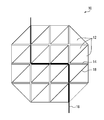
- FIG. 1 shows an embodiment of the present invention in a top plan view, illustrating a cable housed within the contiguous channel formed between floor panels that are connected in an array.
- FIG. 2 shows (A) top perspective, (B) bottom perspective, (C) top plan, (D) first side elevation, (E) second side elevation, (F) third side elevation, and (G) bottom plan views, respectively, of a floor panel accordingly to an embodiment of the present invention. For clarity, a portion of the raised tread and drainage bores is not shown in (A).
- FIG. 2 also shows (H) top perspective and (I) bottom perspective views, respectively, of an alternative embodiment of the present invention.
- FIG. 3 shows six floor panels according to the embodiment shown in FIGS. 2A to 2G , connected in an array, in (A) top and (C) bottom perspective views, respectively.
- FIG. 3(B) shows a close-up view in detail of the portion indicated in (A)
- FIG. 3(D) shows a close-up view in detail of the portion indicated in (C).
- FIG. 3 also shows (E) a bottom plan view of an array of four floor panels according to the embodiment shown in FIGS. 2H and 2I .
- FIG. 4 shows a laterally cross-sectioned portion of two connected floor panels according to the embodiment shown in FIGS. 2A to 2G in a top plan view, indicating (A) a path for a cable, (B) the seated position, and (C) the unseated position.
- FIG. 5 shows a laterally cross-sectioned portion of two connected floor panels according to another embodiment of the present invention, shown in a top plan view.
- FIG. 6 shows two connected floor panels according to the embodiment shown in FIGS. 2A to 2G in (A) a bottom plan view and (B) a cross-sectional view in detail of the portion indicated by the section lines in (A).
- FIG. 7 shows four floor panels according to the embodiment shown in FIGS. 2A to 2G , with a first pair of connected floor panels stacked on top of a second pair of connected floor panels, in (A) a top perspective view, and (B) a sectional side-elevation view cross-sectioned along the section lines in (A).
- the flooring system 10 includes repeating panel units 12 which together form an array throughout which a contiguous channel 14 is formed for retainably housing a cable 16 or multiple cables (not shown). Where the repeating panel unit 12 is a single floor panel (shown), segments of the contiguous channel 14 are formed between panel units 12 where they connect. Depending on the types of connectors between panel units 12 , connecting panel units 12 may form a segment of the contiguous channel 14 or may form a non-channel-forming connection 18 .
- segments of the contiguous channel may be formed through, between or through and between repeating panel units. While the embodiment shown in FIG. 1 demonstrates a repeating panel unit 12 consisting of a single triangular floor panel assembled in pairs to form square panels presenting four channel-forming sides, the individual floor panels may be triangular, square, rectangular, trapezoidal, hexagonal, polygonal, or any other suitable shape.
- the connecting sides may be generally straight, curved or irregular. All of the connecting sides may be channel-forming (not shown) or less than all of the connecting sides may be channel-forming (shown).
- the repeating panel unit may include a single floor panel (e.g. panel unit 12 ) or may include multiple floor panels (not shown).
- the first floor panel 40 includes a body 42 having a generally planar top surface 44 ( FIGS. 2A and 2C ), a bottom surface 46 ( FIGS. 2B and 2G ) defining a bottom plane 47 , and a first side 48 ( FIGS. 2A and 2D ).
- the first side 48 includes a cable-retaining lip 50 proximal to the top surface 44 and an interlocking support 52 proximal to the bottom plane 47 of the bottom surface 46 .
- the body 42 may or may not be integrally formed.
- the body 42 may be produced by high pressure injection moulding processes or other suitable means.
- the body 42 may be composed of a base polyolefin thermoplastic, optionally containing additives.
- the base polyolefin thermoplastic may contain an additive for superior impact resistance over a wide range of temperatures (e.g. resistant over an operating ambient temperature range of ⁇ 51° C. to +49° C. as per ASTM D256-10 Standard Test Methods for Determining the Izod Pendulum Impact Resistance of Plastics), a non-halogen fire retardant additive (e.g. as per ULC/CAN S102.2-10 standard), an anti-static additive (e.g. as per ANSI/ESD S 7.1-2005 standard within the range of 10E6 to 10E9 ohms of resistance), a UV resistance additive (e.g.
- the dimensions of the floor panels may be any suitable dimensions.
- the first floor panel 40 may form a right angle triangle (as shown in FIG. 2 ) having a first side 48 and a second side 49 ( FIGS. 2A and 2E ) equal to the first side 48 .
- Each of the first side 48 and the second side 49 may be about 70.0 cm to about 110.0 cm across the lateral (i.e. horizontal) plane, for example.
- the first floor panel 40 In the transverse (i.e. vertical) plane, perpendicular to the lateral plane, the first floor panel 40 may be from about 3.0 cm to about 6.0 cm, for example.
- FIGS. 3A to 3D An array of six floor panels 80 - 85 is shown in FIGS. 3A to 3D and a close-up sectional view of two connected floor panels 30 and 62 is shown in FIG. 4 .
- interlocking support 32 of floor panel 30 is shaped to interlock with the interlocking support 60 of floor panel 62 to form a segment of the contiguous channel indicated in FIG. 4 by the stippled cable 64 lying thereon.
- the size of the channel segment so indicated is dependent on the dimensions of its corresponding floor panels, e.g. the distance between the innermost surfaces 66 and 67 of the respective sides from which the interlocking supports 32 and 60 respectively extend.
- each channel segment may be wide enough to accommodate eight or more CAT-sized cables under a top plane defined by the top surface 44 (shown in FIGS. 2A and 2C ).
- the channel formed by interlocking supports 32 and 60 is adapted to retainably house cable 64 , spaced apart from the bottom plane 47 defined by the bottom surface 46 (see FIG. 2B ).
- FIGS. 3A to 3D six floor panels 80 - 85 are shown interlocked in an array.
- channel segments 86 and 88 are formed between floor panels 81 and 82 and between floor panels 82 and 84 , respectively.
- Channel segments 86 and 88 meet at junction 90 such that in a larger array, a contiguous channel is formed (see FIG. 1 ) which includes multiple perpendicular internal sub floor cable runs providing a cable-management system.
- the cable-retaining lip 92 of floor panel 81 may be adapted to overhang its corresponding channel segment 86 so as to at least partially define a gap 94 between cable-retaining lip 92 and opposing cable-retaining lip 96 .
- the gap 94 may be wide enough to accommodate most standard cable diameters but narrow enough so that standard wheeled chairs, carts and gurneys and chair legs will not penetrate the gap 94 .
- the gap 94 may be less than 10 mm across and larger than 6 mm across.
- the gap 94 may be about 8 mm across.
- the cable-retaining lips 92 and 96 protect any cable(s) (not shown) retainably housed within the channel segment 86 from damage and reduce tripping hazards created from loose cables sticking up above the gap 94 .
- the cable retaining lips 92 and 96 need not have a flat edge as shown in FIG. 3B , but may be curved, irregular, digitated or have any other shape suitable for retaining at least a portion of a cable.
- the interlocking support 32 of floor panel 30 may be shaped to interlock with the interlocking support 60 of the floor panel 62 such that movement of the floor panel 30 relative to floor panel 62 is restricted along a lateral (i.e. horizontal) plane.
- interlocking support 32 may include one or more generally T-shaped projections 100 which each extend and widen along the lateral plane.
- an interlocking support may include one or more generally T-shaped retainers 102 which are respectively shaped and disposed for retaining the generally T-shaped projections 100 of floor panel 30 .
- the generally T-shaped projections may have bevelled edges (as shown in FIG. 2A for generally T-shaped projections 20 ).
- FIG. 5 shows a variant of the present invention.
- Interlocking floor panels 110 and 111 have interlocking supports 112 and 113 , respectively.
- Interlocking support 112 has generally T-shaped projections 114 , distinctly shaped from the generally T-shaped projections 100 shown in FIG. 4A
- interlocking support 113 has generally T-shaped retainers 115 , distinctly shaped from the generally T-shaped projections 102 shown in FIG. 4A , but respectively shaped and disposed for retaining the generally T-shaped projections 114 .
- a single floor panel may include both generally T-shaped projections 20 and generally T-shaped retainers 22 disposed on the same side 48 . While the embodiments shown in FIGS. 1 to 7 show each floor panel having both generally T-shaped projections and retainers, corresponding floor panels of a repeating panel unit may include a plurality of generally T-shaped projections without any retainers, or a plurality of generally T-shaped retainers without any projections. These embodiments would then require at least two floor panels to form a repeating panel unit.
- interlocking support 32 may be shaped to interlock with the corresponding interlocking support 60 of the floor panel 62 such that movement of the floor panel 30 relative to floor panel 62 is restricted along the transverse (i.e. vertical) plane.
- the interlocking support 32 may be shaped to interlock with the corresponding interlocking support 60 of the floor panel 62 such that the floor panel 30 is movable relative to floor panel 62 along the lateral (i.e. horizontal) plane between a seated position (shown in FIG. 4B ) and an unseated position (shown in FIG. 4C ), and such that transverse (i.e. vertical) movement of floor panel 30 relative to floor panel 62 is restricted in the seated position but not restricted in the unseated position.
- interlocking support 52 may further include an interlocking surface defining a first portion 54 (shown to the right) and a second portion 56 (shown to the left) juxtaposed along the lateral plane with first and second generally T-shaped projections 20 spaced apart on the first portion and first and second generally T-shaped retainers 22 spaced apart on the second portion.
- interlocking support 52 of the first floor panel 40 is connectable with a corresponding interlocking support of a second floor panel (as shown in FIG. 3A with respect to panels 81 and 82 , for example) by pivoting one of the two panels relative to the other about a common laterally aligned axis centered on the interlocking supports.
- the interlocking surface may include either or both of curved projections 24 extending outward from first side 48 and curved recesses 26 shaped and disposed to receive corresponding curved projections of a second floor panel (not shown) corresponding to the curved projections 24 of the first floor panel 40 .
- the curved projections 24 may be disposed on the first portion 54 and the curved recesses 26 may be disposed on the second portion 56 , however, the curved projections 24 and curved recesses 26 may be disposed in any suitable manner.
- FIGS. 2H and 2I An alternative configuration of generally T-shaped projections 21 and generally T-shaped retainers 23 is shown in FIGS. 2H and 2I , which assemble into an array as shown in FIG. 3E .
- a first panel 120 and a second panel 122 are shown having channel-forming sides 124 and 126 , respectively.
- the first and second panels 120 and 122 may each have a non-channel-forming side 128 and 130 , respectively.
- the first floor panel 120 may have a first (channel-forming) side 124 and a second (channel-forming) side (not shown) such that the non-channel-forming side 128 defines the hypotenuse of an isosceles right triangle defined by all three sides combined.
- the second panel 122 also defines an isosceles right triangle, connecting together the non-channel-forming (i.e. hypotenusal) sides 128 and 130 forms a square floor panel.
- floor panel 40 may have a non-channel-forming side 140 (a side elevation view of which is shown in FIG. 2F ).
- the non-channel-forming side 140 may include an inner face 142 , an outer face 144 , a retainer 146 extending outward from outer face 144 proximal to the bottom plane 47 defined by the bottom surface 46 , and a retainable member 148 formed between the inner face 142 and the outer face 144 and oriented towards the bottom plane 47 .
- the retainer 146 defines a trench open towards the top surface 44 (best shown in FIG. 2B ) that is shaped and disposed to retain a corresponding retainable member disposed on a second floor panel (not shown).
- floor panel 120 has a retainer 160 adapted to retain retainable member 162 of floor panel 122 .
- floor panel 120 is pivoted relative to floor panel 122 about a common laterally aligned axis centered on the non-channel-forming sides 128 and 130 .
- the top surface 44 may be generally smooth or may be irregular.
- the top surface 44 may have a raised tread 150 for providing traction.
- the pattern of the tread 150 may provide traction from any walking direction.
- the bottom surface 24 may include a number of deep support ribs 152 which extend from the undersurface of the body 42 to the ground beneath.
- the support ribs 152 may extend perpendicular to and parallel to a plane defined by the first side 48 or may be configured in any reasonable arrangement that supports the body 42 .
- the bottom surface 46 may also include shallower structural ribs 154 , disposed between the support ribs 152 , which do not extend all the way to the ground.
- the support ribs 152 and the structural ribs 154 may include a number of cutout regions 156 and 158 , which enhance flexibility of the body 42 in two perpendicular directions.
- the top surface 44 and the bottom surface 46 may define a plurality of drainage bores 159 extending through the body 42 of the first floor panel 40 .
- Each drainage bore 159 may be radially tapered to further facilitate drainage.
- the top surface 44 includes a raised tread 150
- the raised tread 150 may be adapted to maximize liquid drainage including sand and loose dirt and/or to exclude water traps.
- the top surface 44 and the bottom surface 46 may define a spike-retaining bore 162 extending through the body 42 such that the first floor panel 40 can be anchored to the ground using a spike.
- the spike-retaining bore 162 may be sized to fit any particular diameter of spike.
- the spike-retaining bore 162 may have an internal diameter of about 1.5 cm to about 2.5 cm or any other suitable diameter.
- the internal diameter of the spike retaining bore 162 may be adapted to allow for the spike to be driven through the spike retaining bore 162 at a predetermined angle from vertical.
- the internal surface of the bore may have a cutout portion 163 sized to receive the finger of a user. This helps the user hold on to the floor panel when a spike is not received in the spike-retaining bore and, for example, facilitates lifting the floor panel during disassembly of the array.
- FIG. 7 shows floor panels 170 and 172 connected by their respective non-channel-forming sides and stacked on top of floor panels 174 and 176 (only visible in FIG. 7B ) also connected by their respective non-channel-forming sides.
- Floor panel 172 may have a spike-retaining bore 180 that is surrounded by an inset edge portion 182 of the top surface 184 and a projecting edge portion 186 of the bottom surface 188 .
- floor panel 176 may have a spike-retaining bore 190 that is surrounded by an inset edge portion 192 of the top surface 194 and a projecting edge portion 196 of the bottom surface 198 .
- the inset edge portion 192 of floor panel 176 may be adapted to receive the projecting edge portion 186 of floor panel 172 (on the top).
- Lateral sliding of stacked floor panels 172 and 176 may be further or alternatively reduced using an opening 200 defined in the top surface 194 of floor panel 176 that is adapted to receive a stacking projection 202 on the bottom surface 188 of floor panel 172 .
Landscapes
- Engineering & Computer Science (AREA)
- Architecture (AREA)
- Civil Engineering (AREA)
- Structural Engineering (AREA)
- General Engineering & Computer Science (AREA)
- Floor Finish (AREA)
Priority Applications (1)
| Application Number | Priority Date | Filing Date | Title |
|---|---|---|---|
| US14/904,623 US9771725B2 (en) | 2013-07-15 | 2014-07-04 | Modular flooring system |
Applications Claiming Priority (3)
| Application Number | Priority Date | Filing Date | Title |
|---|---|---|---|
| US201361846432P | 2013-07-15 | 2013-07-15 | |
| US14/904,623 US9771725B2 (en) | 2013-07-15 | 2014-07-04 | Modular flooring system |
| PCT/CA2014/000553 WO2015006855A1 (fr) | 2013-07-15 | 2014-07-04 | Système de revêtement de sol modulaire |
Publications (2)
| Publication Number | Publication Date |
|---|---|
| US20160153202A1 US20160153202A1 (en) | 2016-06-02 |
| US9771725B2 true US9771725B2 (en) | 2017-09-26 |
Family
ID=52345646
Family Applications (1)
| Application Number | Title | Priority Date | Filing Date |
|---|---|---|---|
| US14/904,623 Expired - Fee Related US9771725B2 (en) | 2013-07-15 | 2014-07-04 | Modular flooring system |
Country Status (3)
| Country | Link |
|---|---|
| US (1) | US9771725B2 (fr) |
| CA (1) | CA2953837C (fr) |
| WO (1) | WO2015006855A1 (fr) |
Cited By (4)
| Publication number | Priority date | Publication date | Assignee | Title |
|---|---|---|---|---|
| US10914081B2 (en) * | 2017-12-15 | 2021-02-09 | Wearwell, Llc | Interlocking modular mat with sponge insert |
| WO2021243445A1 (fr) | 2020-05-31 | 2021-12-09 | Osbak Gordon A | Plancher modulaire interverrouillable et son procédé d'assemblage |
| US20230279670A1 (en) * | 2022-03-01 | 2023-09-07 | Suzhou Hred Mat Co., Ltd. | Mat for hidden-type splicing |
| US12031336B2 (en) | 2020-08-26 | 2024-07-09 | Wearwell, Llc | Integrated mat assembly and method of use |
Families Citing this family (7)
| Publication number | Priority date | Publication date | Assignee | Title |
|---|---|---|---|---|
| US9980591B2 (en) | 2016-03-01 | 2018-05-29 | Skip Hop, Inc. | Playmat |
| CA2947352A1 (fr) * | 2016-11-03 | 2018-05-03 | Hockeyshot Inc. | Carreau de plancher de jeu de hockey |
| JP6893097B2 (ja) * | 2017-03-09 | 2021-06-23 | 株式会社イノアック住環境 | フロアパネル材 |
| GB2561384A (en) | 2017-04-13 | 2018-10-17 | Oxford Plastic Sys Ltd | Cover |
| CN110056157B (zh) * | 2019-03-19 | 2020-11-27 | 顾海兵 | 一种快拆地板构件及一种拼装地板 |
| CN116348650A (zh) * | 2020-10-12 | 2023-06-27 | 尊荣设计与交付公司 | 模块化庇护所 |
| US12338648B2 (en) * | 2022-11-07 | 2025-06-24 | Sean Dehlinger | Modular tent floor assembly |
Citations (18)
| Publication number | Priority date | Publication date | Assignee | Title |
|---|---|---|---|---|
| US2950575A (en) * | 1958-01-13 | 1960-08-30 | Hellwig August | Raceway network |
| US4018025A (en) | 1975-11-28 | 1977-04-19 | Pawling Rubber Corporation | Ventilated interlocking floor tile |
| US5197244A (en) * | 1988-10-31 | 1993-03-30 | Kabushiki Kaisha Toshiba | Interior panel unit for permitting arrangement of cables and devices on room floor |
| US5263289A (en) | 1986-10-22 | 1993-11-23 | Cablescape Access Flooring Pty. Limited | Modular hollow floor panels with integral ducting |
| US5787654A (en) * | 1995-09-21 | 1998-08-04 | Sport Court, Inc. | Isogrid tile |
| US5907934A (en) * | 1997-09-22 | 1999-06-01 | Austin; John | Interfacing floor tile |
| US6076315A (en) * | 1996-08-30 | 2000-06-20 | Sumitomo Wiring Systems, Ltd | Floor-wiring structure and floor members for storing cable in such structure |
| US20030084626A1 (en) | 2001-11-06 | 2003-05-08 | Hsieh Juu Rong | Modular raised floor system with cable-receiving groove network |
| USD497213S1 (en) | 2003-10-30 | 2004-10-12 | Jiri Poliacek | Triangle tile module |
| WO2008015045A1 (fr) | 2006-08-01 | 2008-02-07 | Ceramicas Del Foix, S.A. | Panneau de revêtement de sol modulaire |
| US7490443B1 (en) | 2006-03-01 | 2009-02-17 | Bike Track, Inc. | Modular flooring system |
| US20090282769A1 (en) | 2005-06-02 | 2009-11-19 | Moller Jr Jorgen J | Modular floor tile system with sliding lock |
| US20100275541A1 (en) | 2009-05-01 | 2010-11-04 | Unity Creations, Ltd. | Interlocking rubber tiles for playgrounds |
| USD634029S1 (en) | 2008-11-07 | 2011-03-08 | Newage Products Inc. | Floor tile |
| US20110107706A1 (en) | 2009-11-06 | 2011-05-12 | Gregg Fleishman | System of interlocking building blocks |
| US20110120037A1 (en) | 2006-09-27 | 2011-05-26 | Barlow David R | Interlocking floor system with barbs for retaining covering |
| US8006443B2 (en) | 2004-02-20 | 2011-08-30 | Tennessee Mat Company, Inc. | Interlocking modular floor tile |
| USD732208S1 (en) * | 2013-07-15 | 2015-06-16 | John Bradley Matchung | Interconnectable floor panel |
-
2014
- 2014-07-04 US US14/904,623 patent/US9771725B2/en not_active Expired - Fee Related
- 2014-07-04 WO PCT/CA2014/000553 patent/WO2015006855A1/fr not_active Ceased
- 2014-07-04 CA CA2953837A patent/CA2953837C/fr active Active
Patent Citations (19)
| Publication number | Priority date | Publication date | Assignee | Title |
|---|---|---|---|---|
| US2950575A (en) * | 1958-01-13 | 1960-08-30 | Hellwig August | Raceway network |
| US4018025A (en) | 1975-11-28 | 1977-04-19 | Pawling Rubber Corporation | Ventilated interlocking floor tile |
| US5263289A (en) | 1986-10-22 | 1993-11-23 | Cablescape Access Flooring Pty. Limited | Modular hollow floor panels with integral ducting |
| US5197244A (en) * | 1988-10-31 | 1993-03-30 | Kabushiki Kaisha Toshiba | Interior panel unit for permitting arrangement of cables and devices on room floor |
| US5787654A (en) * | 1995-09-21 | 1998-08-04 | Sport Court, Inc. | Isogrid tile |
| US6076315A (en) * | 1996-08-30 | 2000-06-20 | Sumitomo Wiring Systems, Ltd | Floor-wiring structure and floor members for storing cable in such structure |
| US5907934A (en) * | 1997-09-22 | 1999-06-01 | Austin; John | Interfacing floor tile |
| US20030084626A1 (en) | 2001-11-06 | 2003-05-08 | Hsieh Juu Rong | Modular raised floor system with cable-receiving groove network |
| USD497213S1 (en) | 2003-10-30 | 2004-10-12 | Jiri Poliacek | Triangle tile module |
| US8006443B2 (en) | 2004-02-20 | 2011-08-30 | Tennessee Mat Company, Inc. | Interlocking modular floor tile |
| US20090282769A1 (en) | 2005-06-02 | 2009-11-19 | Moller Jr Jorgen J | Modular floor tile system with sliding lock |
| US7490443B1 (en) | 2006-03-01 | 2009-02-17 | Bike Track, Inc. | Modular flooring system |
| US7921618B2 (en) | 2006-03-01 | 2011-04-12 | Bike Track, Inc. | Modular flooring system |
| WO2008015045A1 (fr) | 2006-08-01 | 2008-02-07 | Ceramicas Del Foix, S.A. | Panneau de revêtement de sol modulaire |
| US20110120037A1 (en) | 2006-09-27 | 2011-05-26 | Barlow David R | Interlocking floor system with barbs for retaining covering |
| USD634029S1 (en) | 2008-11-07 | 2011-03-08 | Newage Products Inc. | Floor tile |
| US20100275541A1 (en) | 2009-05-01 | 2010-11-04 | Unity Creations, Ltd. | Interlocking rubber tiles for playgrounds |
| US20110107706A1 (en) | 2009-11-06 | 2011-05-12 | Gregg Fleishman | System of interlocking building blocks |
| USD732208S1 (en) * | 2013-07-15 | 2015-06-16 | John Bradley Matchung | Interconnectable floor panel |
Non-Patent Citations (2)
| Title |
|---|
| International Preliminary Report on Patentability issued in corresponding International Application No. PCT/CA2014/000553, dated Jan. 19, 2016, 5 pages. |
| International Search Report issued in corresponding International Application No. PCT/CA2014/000553, dated Sep. 2, 2014, 3 pages. |
Cited By (7)
| Publication number | Priority date | Publication date | Assignee | Title |
|---|---|---|---|---|
| US10914081B2 (en) * | 2017-12-15 | 2021-02-09 | Wearwell, Llc | Interlocking modular mat with sponge insert |
| US11174648B2 (en) | 2017-12-15 | 2021-11-16 | Wearwell, Llc | Interlocking modular mat with sponge insert |
| US11454037B1 (en) | 2017-12-15 | 2022-09-27 | Wearwell, Llc | Interlocking modular mat with sponge insert |
| WO2021243445A1 (fr) | 2020-05-31 | 2021-12-09 | Osbak Gordon A | Plancher modulaire interverrouillable et son procédé d'assemblage |
| US11873646B2 (en) | 2020-05-31 | 2024-01-16 | Gordon A. OSBAK | Interlockable modular floor tile and method of assembling same |
| US12031336B2 (en) | 2020-08-26 | 2024-07-09 | Wearwell, Llc | Integrated mat assembly and method of use |
| US20230279670A1 (en) * | 2022-03-01 | 2023-09-07 | Suzhou Hred Mat Co., Ltd. | Mat for hidden-type splicing |
Also Published As
| Publication number | Publication date |
|---|---|
| US20160153202A1 (en) | 2016-06-02 |
| CA2953837C (fr) | 2018-08-14 |
| WO2015006855A1 (fr) | 2015-01-22 |
| CA2953837A1 (fr) | 2015-01-22 |
Similar Documents
| Publication | Publication Date | Title |
|---|---|---|
| US9771725B2 (en) | Modular flooring system | |
| US10697130B2 (en) | Modular flooring tiles and system | |
| US10196826B1 (en) | Elevated flooring system | |
| US7921618B2 (en) | Modular flooring system | |
| US7955025B2 (en) | Tile for synthetic grass system | |
| US7145079B1 (en) | Modular cable protector | |
| RU2673160C2 (ru) | Пластиковый блок инфильтрации, система, содержащая множество пластиковых блоков инфильтрации | |
| US9534399B2 (en) | Method of using interlocking mat with integral ramp | |
| US20040258869A1 (en) | Modular plastic flooring | |
| US6598366B2 (en) | Modular raised floor system with cable-receiving groove network | |
| US20160365715A1 (en) | Cable protector with expandable center section | |
| US20070022689A1 (en) | Plastic flooring with improved seal | |
| EP0330669A1 (fr) | Panneaux de sol creux modulaires a gaine solidaire. | |
| CA2876899A1 (fr) | Blocs de construction munis d'un connecteur arriere pour les fixer ensemble | |
| US7364383B2 (en) | Roll-up surface, system and method | |
| US8272624B1 (en) | Fence engageable weed barrier system | |
| US12049749B2 (en) | Module for drainage and method of assembly | |
| US10851514B2 (en) | Building block and methods | |
| US20200181902A1 (en) | Concrete block system, method and connector | |
| CN107002412A (zh) | 铺地模块 | |
| AU2013269711B2 (en) | Ducting chamber ring and module, a ducted chamber and a method of assembling a modular chamber system | |
| WO2012158037A1 (fr) | Ensemble de carreaux pour former un plancher | |
| GB2353543A (en) | Floor tile | |
| EP0857839A2 (fr) | Système de bordure | |
| US10662589B2 (en) | Industrial support mat interlock device |
Legal Events
| Date | Code | Title | Description |
|---|---|---|---|
| STCF | Information on status: patent grant |
Free format text: PATENTED CASE |
|
| FEPP | Fee payment procedure |
Free format text: ENTITY STATUS SET TO MICRO (ORIGINAL EVENT CODE: MICR); ENTITY STATUS OF PATENT OWNER: MICROENTITY |
|
| MAFP | Maintenance fee payment |
Free format text: PAYMENT OF MAINTENANCE FEE, 4TH YEAR, MICRO ENTITY (ORIGINAL EVENT CODE: M3551); ENTITY STATUS OF PATENT OWNER: MICROENTITY Year of fee payment: 4 |
|
| FEPP | Fee payment procedure |
Free format text: MAINTENANCE FEE REMINDER MAILED (ORIGINAL EVENT CODE: REM.); ENTITY STATUS OF PATENT OWNER: MICROENTITY |
|
| LAPS | Lapse for failure to pay maintenance fees |
Free format text: PATENT EXPIRED FOR FAILURE TO PAY MAINTENANCE FEES (ORIGINAL EVENT CODE: EXP.); ENTITY STATUS OF PATENT OWNER: MICROENTITY |
|
| STCH | Information on status: patent discontinuation |
Free format text: PATENT EXPIRED DUE TO NONPAYMENT OF MAINTENANCE FEES UNDER 37 CFR 1.362 |
|
| FP | Lapsed due to failure to pay maintenance fee |
Effective date: 20250926 |