US9776159B2 - Device for conducting sonochemical reactions and processing liquids - Google Patents
Device for conducting sonochemical reactions and processing liquids Download PDFInfo
- Publication number
- US9776159B2 US9776159B2 US15/217,456 US201615217456A US9776159B2 US 9776159 B2 US9776159 B2 US 9776159B2 US 201615217456 A US201615217456 A US 201615217456A US 9776159 B2 US9776159 B2 US 9776159B2
- Authority
- US
- United States
- Prior art keywords
- rotor
- channel
- channel element
- longitudinal axis
- discharge orifice
- Prior art date
- Legal status (The legal status is an assumption and is not a legal conclusion. Google has not performed a legal analysis and makes no representation as to the accuracy of the status listed.)
- Expired - Fee Related
Links
- 239000007788 liquid Substances 0.000 title claims abstract description 72
- 238000012545 processing Methods 0.000 title claims abstract description 12
- 238000006243 chemical reaction Methods 0.000 title description 32
- 238000011144 upstream manufacturing Methods 0.000 claims description 3
- XLYOFNOQVPJJNP-UHFFFAOYSA-N water Substances O XLYOFNOQVPJJNP-UHFFFAOYSA-N 0.000 abstract description 6
- 238000000034 method Methods 0.000 description 17
- 230000008569 process Effects 0.000 description 12
- 230000035485 pulse pressure Effects 0.000 description 10
- 230000003068 static effect Effects 0.000 description 10
- 239000007789 gas Substances 0.000 description 7
- 239000003054 catalyst Substances 0.000 description 6
- 230000006835 compression Effects 0.000 description 6
- 238000007906 compression Methods 0.000 description 6
- 239000000203 mixture Substances 0.000 description 6
- 238000012986 modification Methods 0.000 description 5
- 230000004048 modification Effects 0.000 description 5
- 230000000694 effects Effects 0.000 description 4
- 238000010438 heat treatment Methods 0.000 description 4
- 239000002245 particle Substances 0.000 description 4
- 230000015572 biosynthetic process Effects 0.000 description 3
- 230000006872 improvement Effects 0.000 description 3
- VTYYLEPIZMXCLO-UHFFFAOYSA-L Calcium carbonate Chemical compound [Ca+2].[O-]C([O-])=O VTYYLEPIZMXCLO-UHFFFAOYSA-L 0.000 description 2
- CURLTUGMZLYLDI-UHFFFAOYSA-N Carbon dioxide Chemical compound O=C=O CURLTUGMZLYLDI-UHFFFAOYSA-N 0.000 description 2
- -1 biochemistry Substances 0.000 description 2
- 238000001311 chemical methods and process Methods 0.000 description 2
- 239000003153 chemical reaction reagent Substances 0.000 description 2
- 229940079593 drug Drugs 0.000 description 2
- 239000003814 drug Substances 0.000 description 2
- 239000012776 electronic material Substances 0.000 description 2
- 239000000839 emulsion Substances 0.000 description 2
- 238000005755 formation reaction Methods 0.000 description 2
- 239000011344 liquid material Substances 0.000 description 2
- 230000010355 oscillation Effects 0.000 description 2
- 230000009257 reactivity Effects 0.000 description 2
- 239000011347 resin Substances 0.000 description 2
- 229920005989 resin Polymers 0.000 description 2
- 239000000126 substance Substances 0.000 description 2
- IJGRMHOSHXDMSA-UHFFFAOYSA-N Atomic nitrogen Chemical compound N#N IJGRMHOSHXDMSA-UHFFFAOYSA-N 0.000 description 1
- BVKZGUZCCUSVTD-UHFFFAOYSA-M Bicarbonate Chemical compound OC([O-])=O BVKZGUZCCUSVTD-UHFFFAOYSA-M 0.000 description 1
- OYPRJOBELJOOCE-UHFFFAOYSA-N Calcium Chemical compound [Ca] OYPRJOBELJOOCE-UHFFFAOYSA-N 0.000 description 1
- 230000004913 activation Effects 0.000 description 1
- 239000003570 air Substances 0.000 description 1
- 230000004075 alteration Effects 0.000 description 1
- 238000013459 approach Methods 0.000 description 1
- QVGXLLKOCUKJST-UHFFFAOYSA-N atomic oxygen Chemical compound [O] QVGXLLKOCUKJST-UHFFFAOYSA-N 0.000 description 1
- 230000009286 beneficial effect Effects 0.000 description 1
- 230000008901 benefit Effects 0.000 description 1
- 239000002551 biofuel Substances 0.000 description 1
- 229910052791 calcium Inorganic materials 0.000 description 1
- 239000011575 calcium Substances 0.000 description 1
- 229910000019 calcium carbonate Inorganic materials 0.000 description 1
- 239000001569 carbon dioxide Substances 0.000 description 1
- 229910002092 carbon dioxide Inorganic materials 0.000 description 1
- 239000011203 carbon fibre reinforced carbon Substances 0.000 description 1
- 230000008859 change Effects 0.000 description 1
- 238000003889 chemical engineering Methods 0.000 description 1
- 239000004020 conductor Substances 0.000 description 1
- 238000001816 cooling Methods 0.000 description 1
- 238000007872 degassing Methods 0.000 description 1
- 239000003925 fat Substances 0.000 description 1
- 239000000945 filler Substances 0.000 description 1
- 230000004907 flux Effects 0.000 description 1
- 230000007062 hydrolysis Effects 0.000 description 1
- 238000006460 hydrolysis reaction Methods 0.000 description 1
- 239000003999 initiator Substances 0.000 description 1
- 230000000977 initiatory effect Effects 0.000 description 1
- 230000003993 interaction Effects 0.000 description 1
- 230000007246 mechanism Effects 0.000 description 1
- 230000000813 microbial effect Effects 0.000 description 1
- 239000000178 monomer Substances 0.000 description 1
- 239000002105 nanoparticle Substances 0.000 description 1
- JCXJVPUVTGWSNB-UHFFFAOYSA-N nitrogen dioxide Inorganic materials O=[N]=O JCXJVPUVTGWSNB-UHFFFAOYSA-N 0.000 description 1
- 239000003921 oil Substances 0.000 description 1
- 239000001301 oxygen Substances 0.000 description 1
- 229910052760 oxygen Inorganic materials 0.000 description 1
- 230000037361 pathway Effects 0.000 description 1
- 239000003444 phase transfer catalyst Substances 0.000 description 1
- 150000003904 phospholipids Chemical class 0.000 description 1
- 239000010773 plant oil Substances 0.000 description 1
- 229920000642 polymer Polymers 0.000 description 1
- 238000002360 preparation method Methods 0.000 description 1
- 230000000644 propagated effect Effects 0.000 description 1
- 239000000376 reactant Substances 0.000 description 1
- 230000009467 reduction Effects 0.000 description 1
- 238000011160 research Methods 0.000 description 1
- 239000007787 solid Substances 0.000 description 1
- 238000006467 substitution reaction Methods 0.000 description 1
- 230000001629 suppression Effects 0.000 description 1
- 238000003786 synthesis reaction Methods 0.000 description 1
- 238000012546 transfer Methods 0.000 description 1
- 238000002604 ultrasonography Methods 0.000 description 1
Images


Classifications
-
- B—PERFORMING OPERATIONS; TRANSPORTING
- B01—PHYSICAL OR CHEMICAL PROCESSES OR APPARATUS IN GENERAL
- B01J—CHEMICAL OR PHYSICAL PROCESSES, e.g. CATALYSIS OR COLLOID CHEMISTRY; THEIR RELEVANT APPARATUS
- B01J19/00—Chemical, physical or physico-chemical processes in general; Their relevant apparatus
- B01J19/008—Processes for carrying out reactions under cavitation conditions
-
- B—PERFORMING OPERATIONS; TRANSPORTING
- B01—PHYSICAL OR CHEMICAL PROCESSES OR APPARATUS IN GENERAL
- B01J—CHEMICAL OR PHYSICAL PROCESSES, e.g. CATALYSIS OR COLLOID CHEMISTRY; THEIR RELEVANT APPARATUS
- B01J19/00—Chemical, physical or physico-chemical processes in general; Their relevant apparatus
- B01J19/08—Processes employing the direct application of electric or wave energy, or particle radiation; Apparatus therefor
- B01J19/10—Processes employing the direct application of electric or wave energy, or particle radiation; Apparatus therefor employing sonic or ultrasonic vibrations
-
- B—PERFORMING OPERATIONS; TRANSPORTING
- B06—GENERATING OR TRANSMITTING MECHANICAL VIBRATIONS IN GENERAL
- B06B—METHODS OR APPARATUS FOR GENERATING OR TRANSMITTING MECHANICAL VIBRATIONS OF INFRASONIC, SONIC, OR ULTRASONIC FREQUENCY, e.g. FOR PERFORMING MECHANICAL WORK IN GENERAL
- B06B3/00—Methods or apparatus specially adapted for transmitting mechanical vibrations of infrasonic, sonic, or ultrasonic frequency
-
- B—PERFORMING OPERATIONS; TRANSPORTING
- B01—PHYSICAL OR CHEMICAL PROCESSES OR APPARATUS IN GENERAL
- B01J—CHEMICAL OR PHYSICAL PROCESSES, e.g. CATALYSIS OR COLLOID CHEMISTRY; THEIR RELEVANT APPARATUS
- B01J2219/00—Chemical, physical or physico-chemical processes in general; Their relevant apparatus
- B01J2219/08—Processes employing the direct application of electric or wave energy, or particle radiation; Apparatus therefor
- B01J2219/0869—Feeding or evacuating the reactor
-
- B—PERFORMING OPERATIONS; TRANSPORTING
- B01—PHYSICAL OR CHEMICAL PROCESSES OR APPARATUS IN GENERAL
- B01J—CHEMICAL OR PHYSICAL PROCESSES, e.g. CATALYSIS OR COLLOID CHEMISTRY; THEIR RELEVANT APPARATUS
- B01J2219/00—Chemical, physical or physico-chemical processes in general; Their relevant apparatus
- B01J2219/08—Processes employing the direct application of electric or wave energy, or particle radiation; Apparatus therefor
- B01J2219/0873—Materials to be treated
- B01J2219/0877—Liquid
Definitions
- This invention relates to devices for conducting sonochemical reactions in aqueous and non-aqueous liquid media, to devices utilizing hydrodynamic cavitation effects for conducting the sonochemical reactions and processing liquids utilizing ultra-high energy from the collapse of cavitation bubbles. More specifically, the present invention relates to a device which is effective and useful in the fields of chemistry, electronic materials, biochemistry, water treatment, food, agriculture, medication, and the pharmaceutical industry.
- Sonochemistry is the application of ultrasound to chemical reactions and processes.
- the mechanism causing sonochemical effects in liquids is the phenomenon of ultrasonic cavitation.
- ultrasonic cavitation Up to the present time, it is well known that there are many chemical reactions that essentially alter the speed and yield of finished products under the influence of ultrasonic cavitation.
- sonochemical effects can be observed in chemical reactions and processes: increase in reaction output and speed, changing of reaction pathway and increase in the reactivity of reagents or catalysts, improvement of phase transfer and activation catalysts, avoidance of catalysts and breakage of molecular bonds, improvement of particle and droplets formations and synthesis.
- a method disclosed in U.S. Pat. Nos. 5,937,906; 6,012,492; 6,035,897, for conducting sonochemical reactions and processes using large scale liquid medium volumes involves passing a hydrodynamic liquid flow at a velocity through a flow through channel internally containing at least one element to produce a local constriction of the hydrodynamic liquid flow.
- the velocity of the liquid flow in the local constriction is at least 16 m/sec.
- a hydrodynamic cavitation cavern is created downstream of the local constriction, thereby generating cavitation bubbles.
- the cavitation bubbles are shifted with the liquid flow to an outlet from the flow through channel and the static pressure of the liquid flow is increased to at least 12 psi.
- the cavitation bubbles are then collapsed in the elevated static pressure zone, thereby initiating the sonochemical reactions and processes.
- maximum temperature inside a collapsing bubble can be calculated by:
- the present invention contemplates a new and improved device for conducting sonochemical reactions and processes that makes use of hydrodynamic cavitation for generation of controlled shockwave pressure and temperature conditions in liquids and carries out an ultrafine crush treatment for liquid materials, or achieves effective chemical reactions of liquid materials.
- a device for processing a liquid comprising a housing, a channel element and a rotor, the channel element being connected to the housing and extending at least partially within the housing, a distal portion of the channel element having a cylindrical external surface, the channel element having a first longitudinal axis, the channel element having at least one discharge orifice having a second longitudinal axis which extends through a point on the first longitudinal axis and is perpendicular to the first longitudinal axis, the rotor being mounted on a shaft and being located within the housing, the rotor having a cylindrical internal surface facing the channel element cylindrical external surface, the rotor having at least one rotor channel having a third longitudinal axis which is perpendicular to the first longitudinal axis, the rotor being rotatable about the distal portion of the channel element such that, as the rotor rotates, the rotor channel will periodically line up with the discharge orifice so that the discharge orifice is open, the channel element having at least one local constriction which defines an
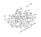
- FIG. 1 is a longitudinal cross-sectional view of a device according to the invention that can be used for conducting sonochemical reactions and processes;
- FIG. 2 is a cross-sectional view of the device shown in FIG. 1 , taken along the plane defined by line A-A in FIG. 1 ;
- FIG. 3 is a longitudinal cross-sectional view of an alternative embodiment of a portion of the device of FIG. 1 ;
- FIG. 4 is a longitudinal cross-sectional view of an alternative embodiment of a portion of the device of FIG. 1 ;
- FIG. 5 is an elevational view of the downstream face or side of an alternative embodiment of a local constriction.
- a range such as 5-25 (or 5 to 25) is given, this means preferably at least 5 and, separately and independently, preferably not more than 25.
- FIGS. 1 and 2 show one embodiment of a device 100 for conducting sonochemical reactions and processes in liquids.
- the device 100 can include a housing 101 defined by a cylindrical housing wall 102 having a longitudinal axis 120 , and a pair of flat or substantially flat end walls 103 , 103 a.
- cylindrical stationary channel element 105 has the longitudinal axis 120 and is mounted in the end wall 103 of the housing 101 .
- Channel element 105 has a proximal portion 122 and a distal portion 124 .
- Channel element 105 defines at least one inlet port 114 and a channel or initial channel 126 .
- Pump 121 supplies liquid to inlet port 114 under pressure.
- Channel 126 is cylindrical as shown but can be rectangular, square or polygonal in cross section.
- Distal portion 124 has a cylindrical external surface 106 (facing the housing wall 102 ) and an end wall 125 .
- Channel element 105 defines a plurality of discharge orifices 107 , 107 a, each having a longitudinal axis which (a) originates at central point 127 on the longitudinal axis 120 and (b) extends perpendicular to the longitudinal axis 120 .
- Two discharge orifices are shown, but there can alternatively be 3, 4, 5, 6, 7, 8, 9, 10, 11, 12 or more discharge orifices, preferably spaced symmetrically around the channel element 105 as shown.
- rotor 108 is located within the housing 101 and is mounted on shaft 109 extending within the housing 101 and has a cylindrical internal surface 110 facing the external surface 106 .
- the shaft 109 is connected to a motive means 130 , such as a motor, effective to rotate the rotor 108 .
- the gap 116 between internal surface 110 and external surface 106 is preferably substantially uniform around the distal portion 124 of the channel element 105 and is preferably 10-1000, 10-500, 10-300, 10-200 or 10-100, microns.
- Rotor 108 is provided with at least one radially-extending rotor channel 111 (four are shown, as 111 , 111 a, 111 b, 111 c ). Alternatively, 2, 3, 5,6, 7, 8, 9, 10, 11, 12 or more rotor channels can be provided, preferably spaced symmetrically around the rotor 108 as shown.
- the rotor channels are preferably positioned such that rotor 108 can rotate to a position where each longitudinal axis of each discharge orifice coincides, at the same time, with the longitudinal axis of a rotor channel, such as is shown in FIG. 2 . As shown in FIGS.
- the rotor channel 111 will periodically line up with the discharge orifice 107 so that the discharge orifice 107 is open and, as the rotor 108 rotates, the discharge orifice 107 will periodically be closed by being covered by the internal surface 110 of the rotor 108 .
- Channel element 105 comprises at least one local constriction 112 , which defines an opening 128 and which can be at least an orifice, nozzle, baffle body or aperture as shown or as is known in the art (the contents of U.S. Pat. No. 5,937,906 are incorporated herein by reference; all of the local constrictions shown therein can be used in the present invention), the downstream end 129 of the local constriction or of the opening or of the orifice or aperture being located at a distance L from the surface 113 of the end wall 125 .
- the surface 113 and the downstream end 129 are preferably flat or substantially flat and preferably oriented perpendicular to longitudinal axis 120 .
- FIG. 4 illustrates an alternative embodiment wherein three local constrictions 112 a (with 2 openings 8 h, 8 j ), 112 b (with 2 openings) and 112 c (with 1 opening) are shown in series.
- the distance L is measured from the downstream side or face 129 of the most downstream local constriction (eg., 112 c ).
- FIG. 5 shows the downstream face or side 129 of an alternative local constriction 112 d, having openings 8 a, 8 b, 8 c, 8 d, 8 e, 8 f, 8 g, which are arranged in parallel, that is, each of these openings is a channel extending through the local constriction 112 d in a direction parallel to longitudinal axis 120 .
- Local constriction 112 d can have 2, 3, 4, 5, 6, 7, 8, 9, 10 or more openings/channels in parallel, preferably arranged symmetrically.
- the local constrictions are in a series, they can all have only one opening (like 112 or 112 c ), all have a plurality of openings in parallel (eg.
- the openings in the local constrictions are preferably cylindrical with a diameter of at least 0.1, 0.3, 0.5, 1, 5, 10, 15, 20, 30, 40, 50 or 60 mm or more, preferably 0.1-60 mm or more, and preferably have a cross sectional area (whether cylindrical or not) corresponding to at least the cross sectional areas of these cylindrical diameters.
- Each opening can have a different diameter or cross-sectional area.
- the channel 126 is preferably cylindrical and preferably has a diameter and a cross sectional area (whether cylindrical or not) which is at least 1, 2, 4, 5, 10, 20, 30, 50, 75, 100, 200, 300, 400, 500 or 600, percent (or more) bigger than the opening 128 in the local constriction 112 .
- the cross sectional area of the channel 126 is preferably substantially the same as the combined cross sectional areas of all the discharge orifices.
- Discharge orifices 107 , 107 a and rotor channels 111 , 111 a, 111 b, 111 c can have a cylindrical, square, rectangular, polygonal or other cross sectional shape and, in one example, the transverse surface area of the rotor channel is equal to or larger than the transverse surface area of the discharge orifice, for example, not more than 1, 2, 3, 5, 7, 9, 10, 15, 20, 30, 40, 50, 70, 90, 100, 200, 300 or 400 percent greater than the transverse surface area of the discharge orifice.
- each discharge orifice can have an inner surface which is tangent with, or coplanar with, the plane defined by surface 113 .
- Housing 101 has an outlet port 115 to allow the exhaust or exit of liquid which has been processed.
- the desirable or preferred distance L can be calculated using the equation: L ⁇ 0.5 c t, where t is the time period in seconds that it takes to close the discharge orifices, that is, to go from open to closed, L is the length in meters, and c is the speed of sound in the liquid in meters per second.
- the length L is preferably at least 5, 10, 20, 30, 40, 50, 70, 100, 200, 300, 400, 500, 600, 700, 800, 900, 1000 or 1250 mm.
- the rotor preferably rotates at at least 500, 700, 900, 1000, 1500, 2000, 2500, 3000, 3500, 4000, 5000, 6000, 7500 or 10,000 RPM.
- the time period (t) that it takes to close the discharge orifices, that is, to go from open to closed, is preferably less than 0.0000068, 0.000027, 0.000067, 0.00013, 0.00067, 0.001, 0.0013, 0.002 or 0.01 seconds.
- each discharge orifice e.g., 107 , 107 a
- a rotor channel e.g., 111 , 111 a, 111 b, 111 c, as shown in FIG. 2 .
- discharge orifice 107 is open, and discharge orifice 107 will be closed when rotor 108 rotates 45 degrees.
- the device 100 generally provides for introduction of a liquid or liquid media into the inlet port 114 and through the local constriction 112 where formations of hydrodynamic cavitation bubbles are generated downstream of the local constriction 112 .
- the preferred time period t is calculated using the equation: t ⁇ 2 L/c.
- pump 121 forces processing liquid through inlet port 114 and the liquid flows through local constriction 112 .
- static pressure applied by pump 121 to the liquid forces a liquid jet through the local constriction 112 and generates a liquid jet containing hydrodynamic cavitation bubbles, for example, downstream of local constriction 112 in channel 126 .
- the liquid then flows through the discharge orifices 107 , 107 a.
- the sudden blockage of processing liquid through all the discharge orifices and thus through channel 126 creates a sudden change in liquid velocity and the kinetic energy is converted to pressure energy, in other words a water hammer hydraulic pulse is produced in channel 126 due to all the discharge orifices being suddenly and simultaneously closed.
- the rotor 108 acts as a rotational dynamic valve capable of producing hydraulic pulses for converting kinetic energy into pressure energy.
- This pulse of pressure is propagated at the velocity of sound from the surface 113 and in a direction against the original flow direction (i.e. arrow entering inlet 114 ) and the pulse is reflected at the local constriction 112 .
- the pressure pulse or surge reaches its maximum height when the time t is: t ⁇ 2 L/c, where t, c and L are as defined above.
- P ⁇ ⁇ c v
- P ⁇ the magnitude of the water hammer hydraulic pulse pressure (Pa)
- ⁇ the density of the liquid (kg/m 3 )
- v the initial velocity of the liquid in the channel (e.g., channel 126 ) before closing (m/s).
- the velocity of the liquid within the length L of the channel (channel 126 ) before closing has to be at least 1.4 m/sec at the exit from the channel 126 for supporting the presence of cavitation bubbles in the channel. More preferably, the velocity of the liquid in the channel 126 before closing is at least 2, 3, 4, 5, 6, 7, 8, 9, 10, 20, 30, 40, 50, 60, 70, 80, 90, 100, 150, 200, 300, 400, 500 or 600 m/sec or more.
- the leakage through the gap 116 between the rotor 108 and the channel element 105 must be minimized.
- This water hammer hydraulic pulse pressure P ⁇ can be several orders of magnitude higher than the static pressure in the liquid, for example, the inlet pressure of the liquid at inlet port 114 . Elevated hydraulic pulse pressure P ⁇ propagates through channel 126 from the surface 113 against the original flow direction and collapses the cavitation bubbles in the liquid jet containing hydrodynamic cavitation bubbles, for example, downstream of local constriction 112 in channel 126 . Elevated hydraulic pulse pressures P ⁇ are generally beneficial for the generation of ultra-high controlled pressure shockwaves and temperature conditions in liquids that result from the collapse of cavitation bubbles.
- T max T 0 ⁇ ( P ⁇ P v ) ( ⁇ - 1 ) / ⁇ ,
- T 0 is the liquid temperature in the device
- P ⁇ is the external hydraulic pulse pressure which initiated cavitation bubble collapse
- ⁇ is the ratio of specific heats of gas or vapor inside the cavitation bubble before collapse, indicating how much heat is released from the gas during the adiabatic compression
- P v is the gas or vapor pressure inside the cavitation bubble before collapse.
- the processing liquids which can be used in the present invention include water, aqueous liquids, organic liquids and mixtures thereof.
- the organic liquids can be low, medium and high molecular weight liquids, such as monomers, polymers, oligomers, plant oils, fats, resins and mixtures thereof.
- the processing liquids can be any liquids which are presently used in the art of hydrodynamic cavitation.
- the liquids can be comprised of a mixture of two or more liquids such as one liquid soluble in or miscible with another liquid as well as mutually insoluble or immiscible liquids, for example, in the form of emulsions.
- the liquids used in the invention can carry solid or semisolid particles or mixtures thereof.
- the liquid can carry particles which act as a reactant, a filler or a catalyst. Mixtures of different particles can be carried by the liquid.
- the liquid can also carry a gaseous component, such as air, oxygen, nitrogen or carbon dioxide.
- utilization of the hydraulic pulse pressure in the liquid flow for compression of the cavitation bubbles is an effective method that leads to a high intensity of sonochemical reactions and an increase in the degree of heating of the medium.
- Use of the devices described herein can increase the rate of chemical reactions, cause reactions to occur under less restrictive conditions, reduce the number of steps required in a reaction or reaction chain, and enhance catalyst efficiency or initiate of reduction at carbon-carbon bonds.
- the present invention can be used with respect to the following sonochemical reactions: preparation of high purity, narrow size distribution nanoparticles and emulsions with uniform shapes; improvement of the performance of phase transfer catalysts and the reactivity of catalysts or reagents; degassing of the liquids and hydrolysis non hydratable phospholipids in oil, promote conversion of dissolved calcium and bicarbonate ions into calcium carbonate and microbial cell disruption, treatment of various bio-fuels, increases both yield and temperature, producing a filled resin to provide electrically and thermally conductive materials.
- the present invention relates to a reaction and processes method which are effective and useful in the fields of chemistry, electronic materials, biochemistry, agriculture, medication, and the pharmaceutical industry.
Landscapes
- Chemical & Material Sciences (AREA)
- Organic Chemistry (AREA)
- Chemical Kinetics & Catalysis (AREA)
- Health & Medical Sciences (AREA)
- General Health & Medical Sciences (AREA)
- Toxicology (AREA)
- Engineering & Computer Science (AREA)
- Mechanical Engineering (AREA)
- Physical Or Chemical Processes And Apparatus (AREA)
Priority Applications (1)
| Application Number | Priority Date | Filing Date | Title |
|---|---|---|---|
| US15/217,456 US9776159B2 (en) | 2015-07-31 | 2016-07-22 | Device for conducting sonochemical reactions and processing liquids |
Applications Claiming Priority (2)
| Application Number | Priority Date | Filing Date | Title |
|---|---|---|---|
| US201562199394P | 2015-07-31 | 2015-07-31 | |
| US15/217,456 US9776159B2 (en) | 2015-07-31 | 2016-07-22 | Device for conducting sonochemical reactions and processing liquids |
Publications (2)
| Publication Number | Publication Date |
|---|---|
| US20170028375A1 US20170028375A1 (en) | 2017-02-02 |
| US9776159B2 true US9776159B2 (en) | 2017-10-03 |
Family
ID=57886491
Family Applications (1)
| Application Number | Title | Priority Date | Filing Date |
|---|---|---|---|
| US15/217,456 Expired - Fee Related US9776159B2 (en) | 2015-07-31 | 2016-07-22 | Device for conducting sonochemical reactions and processing liquids |
Country Status (4)
| Country | Link |
|---|---|
| US (1) | US9776159B2 (de) |
| EP (1) | EP3328528A4 (de) |
| CA (1) | CA2990713A1 (de) |
| WO (1) | WO2017023581A1 (de) |
Cited By (4)
| Publication number | Priority date | Publication date | Assignee | Title |
|---|---|---|---|---|
| US10065167B2 (en) * | 2015-07-08 | 2018-09-04 | Arisdyne Systems, Inc. | Rotor and channel element apparatus with local constrictions for conducting sonochemical reactions with cavitation and methods for using the same |
| US10065158B2 (en) | 2016-08-19 | 2018-09-04 | Arisdyne Systems, Inc. | Device with an inlet suction valve and discharge suction valve for homogenizaing a liquid and method of using the same |
| US10202288B2 (en) * | 2013-08-22 | 2019-02-12 | Sieva D.O.O. | Cavitation device for treatment of water by cavitation |
| US10315172B2 (en) * | 2014-12-22 | 2019-06-11 | Arisdyne Systems, Inc. | Rotor and stator device having bore holes for cavitational mixing |
Families Citing this family (3)
| Publication number | Priority date | Publication date | Assignee | Title |
|---|---|---|---|---|
| CA2964993C (en) * | 2013-11-01 | 2022-05-10 | Mitton Valve Technology Inc. | Cavitation reactor |
| US10639599B2 (en) | 2016-04-12 | 2020-05-05 | Arisdyne Systems, Inc. | Method and device for cavitationally treating a fluid |
| CN108355510A (zh) * | 2018-03-08 | 2018-08-03 | 广州泰若智能化科技有限公司 | 一种新型饮用水有机物的高级催化装置 |
Citations (6)
| Publication number | Priority date | Publication date | Assignee | Title |
|---|---|---|---|---|
| US5937906A (en) | 1997-05-06 | 1999-08-17 | Kozyuk; Oleg V. | Method and apparatus for conducting sonochemical reactions and processes using hydrodynamic cavitation |
| US20040022122A1 (en) | 2002-08-02 | 2004-02-05 | Kozyuk Oleg V. | Devices for cavitational mixing and pumping and methods of using same |
| US20050237855A1 (en) * | 2004-04-23 | 2005-10-27 | Kozyuk Oleg V | Device and method for creating vortex cavitation in fluids |
| RU49608U1 (ru) | 2005-06-16 | 2005-11-27 | Дворников Виктор Миронович | Кавитационный реактор |
| RU2305073C9 (ru) | 2005-07-04 | 2007-12-10 | Степан Григорьевич Николаев | Установка для очистки и обеззараживания воды |
| US20100103768A1 (en) | 2008-10-27 | 2010-04-29 | Cavitation Technologies, Inc. | Cavitation generator |
Family Cites Families (3)
| Publication number | Priority date | Publication date | Assignee | Title |
|---|---|---|---|---|
| CA2175296A1 (en) * | 1996-04-29 | 1997-10-30 | Bruno H. Walter | Flow pulsing method and apparatus for the increase of the rate of drilling |
| US20140316180A1 (en) * | 2013-04-23 | 2014-10-23 | Quantum Vortex, Inc. | Apparatuses and methods for hydrodynamic cavitation treatment of liquids |
| US10065167B2 (en) * | 2015-07-08 | 2018-09-04 | Arisdyne Systems, Inc. | Rotor and channel element apparatus with local constrictions for conducting sonochemical reactions with cavitation and methods for using the same |
-
2016
- 2016-07-22 EP EP16833520.6A patent/EP3328528A4/de not_active Withdrawn
- 2016-07-22 WO PCT/US2016/043644 patent/WO2017023581A1/en not_active Ceased
- 2016-07-22 US US15/217,456 patent/US9776159B2/en not_active Expired - Fee Related
- 2016-07-22 CA CA2990713A patent/CA2990713A1/en not_active Abandoned
Patent Citations (8)
| Publication number | Priority date | Publication date | Assignee | Title |
|---|---|---|---|---|
| US5937906A (en) | 1997-05-06 | 1999-08-17 | Kozyuk; Oleg V. | Method and apparatus for conducting sonochemical reactions and processes using hydrodynamic cavitation |
| US6012492A (en) | 1997-05-06 | 2000-01-11 | Kozyuk; Oleg V. | Method and apparatus for conducting sonochemical reactions and processes using hydrodynamic cavitation |
| US6035897A (en) | 1997-05-06 | 2000-03-14 | Kozyuk; Oleg Vyacheslavovich | Method and apparatus for conducting sonochemical reactions and processes using hydrodynamic cavitation |
| US20040022122A1 (en) | 2002-08-02 | 2004-02-05 | Kozyuk Oleg V. | Devices for cavitational mixing and pumping and methods of using same |
| US20050237855A1 (en) * | 2004-04-23 | 2005-10-27 | Kozyuk Oleg V | Device and method for creating vortex cavitation in fluids |
| RU49608U1 (ru) | 2005-06-16 | 2005-11-27 | Дворников Виктор Миронович | Кавитационный реактор |
| RU2305073C9 (ru) | 2005-07-04 | 2007-12-10 | Степан Григорьевич Николаев | Установка для очистки и обеззараживания воды |
| US20100103768A1 (en) | 2008-10-27 | 2010-04-29 | Cavitation Technologies, Inc. | Cavitation generator |
Non-Patent Citations (4)
| Title |
|---|
| Mason, T. J.,"Advances in Sonochemistry", vol. 3, 1993, Jai Press Inc., pp. cover,v-ix,1. |
| Pandit, A. B., Moholkar, V. S., "Harness Cavitation to Improve Processing", Chemical Engineering Process, Jul. 1996, pp. 57-69. |
| Suslick, K. S.,"Sonochemistry", Science, vol. 247, Mar. 23, 1990, pp. 1439-1445. |
| The International Search Report and Written Opinion issued in corresponding International PCT Application No. PCT/US2016/043644; Dated: Nov. 3, 2016. |
Cited By (4)
| Publication number | Priority date | Publication date | Assignee | Title |
|---|---|---|---|---|
| US10202288B2 (en) * | 2013-08-22 | 2019-02-12 | Sieva D.O.O. | Cavitation device for treatment of water by cavitation |
| US10315172B2 (en) * | 2014-12-22 | 2019-06-11 | Arisdyne Systems, Inc. | Rotor and stator device having bore holes for cavitational mixing |
| US10065167B2 (en) * | 2015-07-08 | 2018-09-04 | Arisdyne Systems, Inc. | Rotor and channel element apparatus with local constrictions for conducting sonochemical reactions with cavitation and methods for using the same |
| US10065158B2 (en) | 2016-08-19 | 2018-09-04 | Arisdyne Systems, Inc. | Device with an inlet suction valve and discharge suction valve for homogenizaing a liquid and method of using the same |
Also Published As
| Publication number | Publication date |
|---|---|
| EP3328528A4 (de) | 2019-03-13 |
| WO2017023581A1 (en) | 2017-02-09 |
| CA2990713A1 (en) | 2017-02-09 |
| EP3328528A1 (de) | 2018-06-06 |
| US20170028375A1 (en) | 2017-02-02 |
Similar Documents
| Publication | Publication Date | Title |
|---|---|---|
| US10065167B2 (en) | Rotor and channel element apparatus with local constrictions for conducting sonochemical reactions with cavitation and methods for using the same | |
| US20170028375A1 (en) | Device for conducting sonochemical reactions and processing liquids | |
| US7762715B2 (en) | Cavitation generator | |
| US6012492A (en) | Method and apparatus for conducting sonochemical reactions and processes using hydrodynamic cavitation | |
| US6857774B2 (en) | Devices for cavitational mixing and pumping and methods of using same | |
| Zhang et al. | Ultrasound-assisted gas–liquid mass transfer process in microreactors: the influence of surfactant, channel size and ultrasound frequency | |
| Dehane et al. | Insight into the impact of excluding mass transport, heat exchange and chemical reactions heat on the sonochemical bubble yield: Bubble size-dependency | |
| US9782741B2 (en) | Method for conducting sonochemical reactions and processes | |
| US20180303135A1 (en) | Material processing by controllably generated acoustic effects | |
| US20090309244A1 (en) | Procedure and device of high efficiency for the generation of drops and bubbles | |
| Song et al. | Liquid-liquid colliding micro-dispersion and general scaling laws in novel T-junction microdevices | |
| RU2131094C1 (ru) | Кавитационный тепловой генератор | |
| RU2016268C1 (ru) | Эжекторная установка | |
| US8453997B2 (en) | Supersonic nozzle | |
| EP1501626B1 (de) | Vorrichtung und verfahren zur erzeugung von hydrodynamischer kavitation in fluiden | |
| RU2412750C1 (ru) | Способ разрушения молекулярных связей в жидких средах и установка для его осуществления | |
| US10233097B2 (en) | Liquid treatment apparatus with ring vortex processor and method of using same | |
| RU85838U1 (ru) | Эжектор с газоструйными ультразвуковыми генераторами | |
| Dubovkina | Modeling of alternating impulses of pressure for hydrodynamic conditions in mixing technology | |
| RU2554432C2 (ru) | Механический способ прямого получения водорода и кислорода из жидкости водородогазогенератора для его осуществления | |
| SONOCHEMICA | 2) Patent Application Publication o Pub. No.: US 2015/0367313A1 | |
| RU111457U1 (ru) | Устройство для создания акустических колебаний в проточной жидкой среде |
Legal Events
| Date | Code | Title | Description |
|---|---|---|---|
| AS | Assignment |
Owner name: ARISDYNE SYSTEMS, INC., OHIO Free format text: ASSIGNMENT OF ASSIGNORS INTEREST;ASSIGNOR:KOZYUK, OLEG;REEL/FRAME:039498/0748 Effective date: 20160721 |
|
| STCF | Information on status: patent grant |
Free format text: PATENTED CASE |
|
| FEPP | Fee payment procedure |
Free format text: MAINTENANCE FEE REMINDER MAILED (ORIGINAL EVENT CODE: REM.); ENTITY STATUS OF PATENT OWNER: SMALL ENTITY |
|
| LAPS | Lapse for failure to pay maintenance fees |
Free format text: PATENT EXPIRED FOR FAILURE TO PAY MAINTENANCE FEES (ORIGINAL EVENT CODE: EXP.); ENTITY STATUS OF PATENT OWNER: SMALL ENTITY |
|
| STCH | Information on status: patent discontinuation |
Free format text: PATENT EXPIRED DUE TO NONPAYMENT OF MAINTENANCE FEES UNDER 37 CFR 1.362 |
|
| FP | Lapsed due to failure to pay maintenance fee |
Effective date: 20211003 |