US9790980B2 - Fastener nut for channel framing - Google Patents
Fastener nut for channel framing Download PDFInfo
- Publication number
- US9790980B2 US9790980B2 US14/581,588 US201414581588A US9790980B2 US 9790980 B2 US9790980 B2 US 9790980B2 US 201414581588 A US201414581588 A US 201414581588A US 9790980 B2 US9790980 B2 US 9790980B2
- Authority
- US
- United States
- Prior art keywords
- nut
- fastener
- channel framing
- fastener nut
- wings
- Prior art date
- Legal status (The legal status is an assumption and is not a legal conclusion. Google has not performed a legal analysis and makes no representation as to the accuracy of the status listed.)
- Active, expires
Links
Images




Classifications
-
- F—MECHANICAL ENGINEERING; LIGHTING; HEATING; WEAPONS; BLASTING
- F16—ENGINEERING ELEMENTS AND UNITS; GENERAL MEASURES FOR PRODUCING AND MAINTAINING EFFECTIVE FUNCTIONING OF MACHINES OR INSTALLATIONS; THERMAL INSULATION IN GENERAL
- F16B—DEVICES FOR FASTENING OR SECURING CONSTRUCTIONAL ELEMENTS OR MACHINE PARTS TOGETHER, e.g. NAILS, BOLTS, CIRCLIPS, CLAMPS, CLIPS OR WEDGES; JOINTS OR JOINTING
- F16B37/00—Nuts or like thread-engaging members
- F16B37/04—Devices for fastening nuts to surfaces, e.g. sheets, plates
- F16B37/045—Devices for fastening nuts to surfaces, e.g. sheets, plates specially adapted for fastening in channels, e.g. sliding bolts, channel nuts
-
- Y—GENERAL TAGGING OF NEW TECHNOLOGICAL DEVELOPMENTS; GENERAL TAGGING OF CROSS-SECTIONAL TECHNOLOGIES SPANNING OVER SEVERAL SECTIONS OF THE IPC; TECHNICAL SUBJECTS COVERED BY FORMER USPC CROSS-REFERENCE ART COLLECTIONS [XRACs] AND DIGESTS
- Y10—TECHNICAL SUBJECTS COVERED BY FORMER USPC
- Y10T—TECHNICAL SUBJECTS COVERED BY FORMER US CLASSIFICATION
- Y10T29/00—Metal working
- Y10T29/49—Method of mechanical manufacture
- Y10T29/49826—Assembling or joining
- Y10T29/49947—Assembling or joining by applying separate fastener
-
- Y—GENERAL TAGGING OF NEW TECHNOLOGICAL DEVELOPMENTS; GENERAL TAGGING OF CROSS-SECTIONAL TECHNOLOGIES SPANNING OVER SEVERAL SECTIONS OF THE IPC; TECHNICAL SUBJECTS COVERED BY FORMER USPC CROSS-REFERENCE ART COLLECTIONS [XRACs] AND DIGESTS
- Y10—TECHNICAL SUBJECTS COVERED BY FORMER USPC
- Y10T—TECHNICAL SUBJECTS COVERED BY FORMER US CLASSIFICATION
- Y10T29/00—Metal working
- Y10T29/49—Method of mechanical manufacture
- Y10T29/49826—Assembling or joining
- Y10T29/49947—Assembling or joining by applying separate fastener
- Y10T29/49948—Multipart cooperating fastener [e.g., bolt and nut]
Definitions
- the present invention generally relates to a fastener nut for channel framing, and a channel framing assembly including the fastener nut.
- strut channel One type of channel framing is called strut channel, which is used in the construction and electrical industries for structural support, often for supporting wiring, plumbing, or mechanical components such as air conditioning or ventilation systems.
- Strut channel is usually formed from metal sheet, folded over to define an open channel with interned lips to provide additional stiffness and as a location to mount interconnecting components.
- a fastener nut may be inserted into the interior of the channel framing, in opposing relationship to the open channel, for use in securing a part to the open channel side of the strut channel.
- the side of the strut channel opposite the open channel usually has holes of some sort in the base, to facilitate interconnection or fastening strut to underlying building structures.
- a fastener nut for securing a part to channel framing having a length and an open interior defining at least one internal, generally T-shaped track extending lengthwise of the channel framing.
- the fastener nut includes a nut body having a top, a bottom, opposite first and second longitudinal ends, opposite sides extending between the opposite longitudinal ends.
- a fastener opening extends from the top toward the bottom for receiving a fastener for securing the part to the channel framing, and a length extending between the opposite first and second longitudinal ends.
- First and second wings of the fastener nut extend longitudinally outward from the respective first and second longitudinal ends of the body.
- the first and second wings have respective terminal ends defining an effective wing span therebetween that is greater than the length of the body such that at least a portion of the fastener nut has a generally T-shaped side profile.
- the fastener nut is insertable in the generally T-shaped track of the channel framing to allow the fastener nut to slide along the length of the channel framing and to restrict transverse movement of the fastener nut in the interior, relative to length of the framing, for use in positioning the fastener nut along the channel framing.
- channel framing assembly generally includes channel framing having a length and an open interior defining at least one internal, generally T-shaped track extending lengthwise of the channel framing, and a fastener nut for securing a part to the channel framing.
- the fastener nut includes a nut body having a top, a bottom, opposite first and second longitudinal ends, opposite sides extending between the opposite longitudinal ends, a fastener opening extending from the top toward the bottom for receiving a fastener for securing the part to the channel framing, and a length extending between the opposite first and second longitudinal ends.
- First and second wings extend longitudinally outward from the respective first and second longitudinal ends of the body.
- the first and second wings having respective terminal ends defining an effective wing span therebetween that is greater than the length of the body such that at least a portion of the fastener nut has a generally T-shaped side profile.
- the fastener nut is insertable in the generally T-shaped track of the channel framing to allow the fastener nut to slide along the length of the channel framing and to restrict transverse movement of the fastener nut in the interior, relative to length of the framing, for use in positioning the fastener nut along the channel framing.
- a method of assembling a channel framing assembly generally comprises inserting a fastener nut in a generally T-shaped track defined by an interior of channel framing.
- the fastener nut includes: a nut body having a top, a bottom, opposite first and second longitudinal ends, opposite sides extending between the opposite longitudinal ends, a fastener opening extending from the top toward the bottom for receiving a fastener for securing a part to the channel framing, and a length extending between the opposite first and second longitudinal ends; and first and second wings extending longitudinally outward from the respective first and second longitudinal ends of the body, the first and second wings having respective terminal ends defining an effective wing span therebetween that is greater than the length of the body such that at least a portion of the fastener nut has a generally T-shaped side profile.
- a part is secured to an exterior of the channel framing using the fastener nut.
- FIG. 1 is a front perspective of one embodiment of channel framing for use in a channel framing assembly
- FIG. 2 is a front elevation of the channel framing, with upper and lower T-shaped tracks defined by an interior of the channel framing being shown in broken lines;
- FIG. 3 is similar to FIG. 2 , except with left and right T-shaped tracks defined by an interior of the channel framing being shown in broken lines;
- FIG. 4 is a front perspective of one embodiment of a fastener nut for use with channel framing for forming a channel framing assembly;
- FIG. 5 is a bottom perspective of the fastener nut
- FIG. 6 is a left elevation of the fastener nut (the right elevation being identical);
- FIG. 7 is a front elevation of the fastener nut (the rear elevation being identical);
- FIG. 8 is a top plan view of the fastener nut
- FIG. 9 is a bottom plan view of the fastener nut
- FIG. 10 is an exploded view of one embodiment of a channel framing assembly including a plurality of the fastener nuts and the channel framing;
- FIG. 11 is a front elevation of the channel framing assembly in FIG. 10 ;
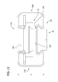
- FIG. 12 is an exploded view of a second embodiment of a channel framing assembly including a plurality of the fastener nuts and the channel framing;
- FIG. 13 is a front elevation of the channel framing assembly in FIG. 12 ;
- FIG. 14 is a perspective of a second embodiment of a fastener nut
- FIG. 15 is a left elevation of the second fastener nut
- FIG. 16 is a top elevation of the second fastener nut
- FIG. 17 is a front elevation of a third embodiment of a channel framing assembly including a plurality of the second fastener nuts and the channel framing;
- FIG. 18 is a perspective of a third embodiment of a fastener nut
- FIG. 19A is a front elevation of a third embodiment of a channel framing assembly including a plurality of the third nuts;
- FIG. 19B is similar to FIG. 19B , but showing the third nuts in left and right tracks of the channel framing;
- FIG. 20 is a perspective of a fourth embodiment of a fastener nut
- FIG. 21 is a front elevation of a fourth embodiment of a channel framing assembly including the fourth embodiment of the fastener nut;
- FIG. 22 is another example of the fourth embodiment of the channel framing assembly
- FIG. 23 is a perspective of a fifth embodiment of a fastener nut
- FIG. 24 is a bottom perspective of the fifth embodiment of the fastener nut
- FIG. 24A is a bottom plan view of the fifth embodiment of the fastener nut
- FIG. 25 is a front elevation of a fifth embodiment of a channel framing including the fifth embodiment of the fastener nut.
- FIG. 26 is another example of the fifth embodiment of the channel framing assembly.
- the present disclosure is directed to a fastener nut for channel framing, one embodiment of which is indicated generally at reference numeral 8 in FIGS. 4-9 .
- the disclosure is also directed to a channel framing assembly 9 including the fastener nut 8 and channel framing 10 (see, e.g., FIGS. 10-11 ).
- the channel framing assembly 9 is configured for use in securing a part P (such as bracket) to the assembly.
- the channel framing assembly 9 may be constructed for use in many different fields, industries, and applications, including, but not limited to, safety grating industry, spring steel fastener industry, cable trays and ladders, pipe hangers, solar industry, racks and runways, electrical enclosures, seismic industry, and rooftop supports.
- the channel framing 10 is elongate with a generally square or rectangular cross-sectional shape having four sides and a longitudinal axis A extending along its length.
- the body 11 of the framing 10 has an upper side 12 , a lower side 14 , a right side 16 , and a left side 18 (each indicated generally).
- the terms defining relative locations and positions of structures and components of the channel framing including but not limited to the terms “upper,” “lower,” “right,” “left,” “top,” and “bottom,” are meant to provide a point of reference for such components and structures as shown in the drawings, with the understanding that the respective relative locations of such components and structures will depend on the orientation of the channel framing in use.
- the terms “inner” and “outer” are relative locations with respect to the longitudinal axis A of the channel framing 10 .
- the upper side 12 (or slot side) defines a continuous opening or slot 19 (i.e., the upper side is open) having a width W 1 ( FIG. 2 ).
- the upper side 12 has outer portions 13 on either side of the slot 19 , and inturned (or downwardly extending, as illustrated) lips 20 defining the slot and leading to an open interior 22 of the channel framing 10 .
- each of the lower, right and left sides 14 , 16 , 18 , respectively, of the channel framing 10 has an inward portion, generally indicated at 23 , and opposite outer portions 24 on either side of the inward portion, extending lengthwise of channel framing 10 .
- An exterior of the inward portion 23 defines an external fitting groove 26
- an interior surface of the inward portion defines an internal rail 27 .
- the illustrated channel framing 10 includes respective left, right, and lower fitting grooves 26 and corresponding left, right, and lower internal rails 27 .
- Each inward portion 23 includes opposing side walls 28 extending generally inwardly from the respective ones of the outer portions 24 of the corresponding side 14 , 16 , 18 .
- the side walls 28 extend to a planar inner wall 30 that spans between and interconnects the side walls.
- the side walls 28 flare away from one another as they extend inward from the outer portions 24 toward the inner wall 30 so that each inward portion 23 has a generally dovetail cross-sectional shape or longitudinal end profile. It is understood that the inner portion 23 , including one or both of the fitting groove 26 and the internal rail 27 , may be of other shapes and configurations without departing from the scope of the present disclosure.
- openings 31 extend through each of the inner walls 30 of the inward portions 23 of the left, right, and lower sides 18 , 16 , 14 , respectively.
- a fastener F e.g., a bolt
- the openings 31 may be, for example, knockouts, or punched, or half-slots, or slots, as are generally known in the art.
- the openings 31 in the channel framing 10 will be the same type of opening, although the same channel framing may include a mix of different types of openings, such as shown in the illustrated embodiments. It is also understood that the sides may not include openings without departing from the scope of the present invention.
- the fitting grooves 26 are substantially identical to one another.
- Each fitting groove 26 has a generally dovetail-shaped profile with a first relatively narrower width W 2 (e.g., a minimum width) adjacent its entrance and a second relatively wider width W 3 (e.g., a maximum width) adjacent the inner wall 30 .
- the fitting grooves 26 are used for securing a fitting, such as the fastener nut 8 , to the channel framing 10 .
- the fastener nut 8 of the present disclosure may be inserted in the fitting grooves 26 for securing the part P (e.g., the bracket) to the exterior of the channel framing 10 .
- fittings which include a coupling component that is complementary to the fitting grooves 26 (e.g., a dovetail-shaped coupling component that can be inserted into the dovetail-shaped fitting groove) can also be used with the channel framing 10 .
- Each rail 27 has a generally dovetail-shaped profile with opposite internal shoulders 32 at the junctions of the inner wall 30 and the side walls 28 . Accordingly, the left and right rails 27 have upper and lower internal shoulders 32 , as illustrated, and the lower rail 27 has left and right internal shoulders 32 , as illustrated.
- the open interior 22 of the channel framing 10 defines at least one track in which the fastener nut 8 can be inserted for use in positioning the fastener nut at a desired location along the length of the channel framing, as explained in more detail below. Referring to FIGS.
- FIG. 2 includes a general outline (shown in broken line) of both a first T-shaped track 40 (e.g., an upper T-shaped track), defined by the inturned lips 20 , and the upper shoulders 32 and inner faces (defined by the inner walls 30 ) of the respective left and right internal rails; and a second T-shaped track 42 (e.g., a lower T-shaped track), defined by the lower shoulders 32 and inner faces (defined by the inner walls 30 ) of the respective left and right internal rails 27 , and the inner face (defined by the inner wall 30 ) of the lower internal rail.
- a first T-shaped track 40 e.g., an upper T-shaped track
- a second T-shaped track 42 e.g., a lower T-shaped track
- FIG. 3 includes a general outline (shown in broken line) of both a third T-shaped track 44 (e.g., a left T-shaped track), defined by the left inturned lip 20 , the inner face (defined by the inner wall 30 ) of the left internal rail 27 , and the left shoulder and inner face (defined by the inner wall 30 ) of the lower internal rail; and a fourth T-shaped track 46 (e.g., a right T-shaped track) defined by the right inturned lip 20 , the inner face (defined by the inner wall 30 ) of the right internal rail 27 , and the right shoulder and inner face (defined by the inner wall 30 ) of the lower internal rail.
- a third T-shaped track 44 e.g., a left T-shaped track
- the fourth T-shaped track 46 e.g., a right T-shaped track
- the channel framing 10 may be formed from a sheet of rigid metal, such as low carbon steel, stainless steel, aluminum, or other metals, or from other material, such as fiberglass or plastic.
- the channel framing 10 may be cold formed using a rolling mill, such as when forming the channel framing from steel, or the channel framing may be extruded from an extrusion die, such as when forming the channel framing from aluminum.
- the channel framing 10 may be formed in other ways.
- the channel framing 10 may be formed from a metal sheet having uniform thickness from about 0.5 mm to about 4 mm.
- the channel framing 10 may be formed from 18 gauge (1.2 mm) steel sheet metal, or from 20 gauge (0.9 mm) steel sheet metal.
- the dimension of each of the width and height of the channel framing 10 may be 53.5 mm, as opposed to 50 mm.
- the fastener nut 8 includes a nut body, generally indicated at 52 , and opposite end extensions (e.g., integral extensions) or wings 54 extending outward from respective opposite longitudinal ends 56 (e.g., left and right ends) of the body.
- opposite end extensions e.g., integral extensions
- wings 54 extending outward from respective opposite longitudinal ends 56 (e.g., left and right ends) of the body.
- the terms denoting relative locations and positions of structures and components of the fastener nut including but not limited to the terms “upper,” “lower,” “right,” “left,” “top,” and “bottom,” are meant to provide a point of reference for such components and structures of the fastener nut as shown in FIGS.
- the nut body 52 has a top 60 , a bottom 62 , and opposite sides 64 extending longitudinally (i.e., along a length L 1 of the fastener nut 8 ; e.g., FIG. 6 ) between the opposite longitudinal ends 56 .
- the longitudinal ends 56 are rounded (e.g., radiused) between the opposite sides 64 to facilitate insertion and positioning of the fastener nut 8 in a selected one of the T-shaped tracks 42 , 44 , 46 , 48 in a crosswise or transverse orientation relative to the longitudinal axis A of the channel framing 10 , as explained in detail below.
- the top 60 of the body portion 52 defines lip-receiving grooves 66 adjacent the opposite longitudinal ends 56 of the body portion and the wings 54 .
- the lip-receiving grooves 66 extend generally transverse to the length L 1 of the fastener nut 8 , and are configured for receiving the inturned lips 20 when the fastener nut is fastened within the upper T-shaped track 40 ( FIG. 2 ).
- a plurality of teeth 68 are disposed in the lip-receiving grooves 66 to facilitate frictional engagement with the inturned lips 20 .
- the bottom 62 of the nut body 52 is generally planar (e.g., flat) although it may have other contours.
- a threaded fastener opening 70 (e.g., a through opening) extends from the top 60 through the bottom 62 of the nut body 52 , in a direction generally transverse (e.g., orthogonal) to the length L 1 of the fastener nut 8 .
- the fastener opening 70 receives a fastener F (e.g., a threaded bolt or threaded stud; e.g., FIGS.
- the fastener opening 70 may be non-threaded and/or may be a blind opening, as opposed to the illustrated through opening.
- a threaded fastener opening may extend from the top 60 toward the bottom 62 but does not extend through the bottom.
- Each of the sides 64 of the nut body 52 has a lower, flared portion 72 that flares outward toward the bottom 62 of the body 52 such that the sides 64 and the bottom together define a generally dovetail shape.
- an end profile of the body 52 (particularly, the end profile defined by the sides 64 and the bottom 62 ), as shown in FIG. 7 , generally corresponds to the end profiles (or cross-sectional shapes) of the fitting grooves 26 defined by the channel framing 10 .
- the body 52 in particular the flared portion 72 , is sized so that it is capable of being slidingly received and captured in the grooves 26 , as shown in FIGS. 11 and 13 , through the open longitudinal ends of the grooves.
- the fastener nut 8 can slide longitudinally within the groove, but the fastener nut is inhibited from being withdrawn from the groove in a direction transverse from the longitudinal axis A of the channel framing.
- the fastener nut 8 can be positioned at a desired longitudinal location on the exterior of the channel framing 10 by sliding the fastener nut lengthwise of the channel framing within the groove 26 .
- the fastener nut 8 has a maximum width W 4 at the dovetail portion of the nut body 52 that is less than the width W 1 of the slot 19 in the upper side 12 of the channel framing 10 so that the fastener nut can be inserted through the slot and into the interior 22 of the channel framing, as explained in more detail below.
- the fastener nut 8 also has a height H 1 extending between the top 60 and the bottom 62 of the nut body 52 .
- the wings 54 extend longitudinally outward from respective longitudinal ends 56 of the nut body 52 adjacent the top 60 of the nut body.
- the wings 54 comprise flanges having generally planar upper surfaces that are generally coplanar (i.e., flush) with the top 60 of the nut body.
- the wings 54 may have other shapes and configurations.
- the wings 54 have respective terminal ends and together the wings define an effective wing span WS extending between the terminal ends of the wings, which in the illustrated embodiment is the same as the length L 1 of the fastener nut 8 .
- the effective wing span WS is greater than a length L 2 of the nut body 52 such that at least a portion of the fastener nut 8 has a generally T-shaped side profile.
- the entirety of the fastener nut 8 has a generally T-shaped profile, although it is contemplated that the fastener nut may have a cross-shaped profile where the top 60 of the nut body 52 extends above the wings 54 .
- a portion of the fastener nut i.e., the portion of the fastener nut below the plane defined by the upper surface of the wings
- Diagonally-opposite rounded portions 78 of the terminal ends of the wings 54 are rounded (radiused) widthwise of the wings so that the terminal ends of the wings fall off toward diagonally-opposite corners of the wings.
- These diagonally-opposite rounded portions 78 facilitate insertion of the wings 54 into the respective T-shaped tracks 40 , 42 , 44 , 46 as the fastener nut 8 is rotated to a position that is generally traverse or crosswise relative to the longitudinal axis A of the channel framing 10 .
- Remaining portions 80 of the terminal ends of the wings 54 are substantially squared off to inhibit over rotation of the fastener nut 8 in the T-shaped tracks 40 , 42 , 44 , 46 .
- the wings 54 are formed integrally with the nut body, although it is contemplated that the wings may be formed separately and then fastened to the nut body.
- the fastener nut 8 may be formed by a stamping operation or other suitable operation.
- the fastener nut 8 may be formed from metal, such as a zinc-coated, heat treated, AISI 1018 steel having a Rockwell hardness of 30-50 C and more preferably 40-45 C. Other materials may be used.
- the wings may be formed separate from the nut body and then secured to the nut body, such as by fastener(s), welding, or in other ways.
- the wings may be a single, integrally-formed, monolithic component, or the wings may be formed separately as individual components.
- the fastener nut 8 may be inserted through the slot 19 so that the length L 1 of the fastener nut runs along the length of the slot and the bottom 62 of the nut body 52 faces the lower side 14 of the channel framing.
- the fastener nut 8 may be rotated 90 degrees (or a quarter turn) so that the wings move past (e.g., laterally beyond) the upper shoulders 32 of the respective left and right rails 27 and become orientated generally crosswise or transverse to the length of the channel framing.
- the fastener nut 8 is rotating, the rounded portions 78 of the terminal ends of the wings 54 enter the lateral portions of the upper T-shaped track 40 first, and the diagonally-opposite corners at the squared off portions 80 of the terminal ends inhibit rotation more than about 90 degrees.
- the fastener nut 8 may be orientated such that its length L 1 (and wingspan WS) is generally crosswise or transverse to the length of the channel framing 10 , and then the fastener nut may be inserted directly into the upper T-shaped track 40 through one of the open longitudinal ends of the channel framing.
- the fastener nut 8 may be inserted into the upper T-shaped track in other ways. With the fastener nut 8 properly inserted in the upper T-shaped track 40 , the fastener nut may be slid within the T-shaped track to a desired location along the length of the channel framing 10 , while remaining slidingly captured between the inturned lips 20 and the upper shoulders 32 of the respective left and right internal rails 27 . More than one fastener nut 8 can be inserted into the upper T-shaped track 40 , and both the upper and the lower T-shaped tracks 40 , 42 may concurrently have fastener nuts therein.
- the fastener nut 8 may be inserted through the slot 19 so that the length L 1 of the fastener nut runs along the length of the slot and the top 60 of the nut body 52 faces the lower side 14 of the channel framing 10 (i.e., the fastener nut is upside down).
- the fastener nut With the top 60 of the fastener nut 8 resting on the inner, planar portion of the lower rail 27 or once the wings 54 pass by or clear the lower shoulders 32 of the left and right rails, the fastener nut may be rotated 90 degrees (or a quarter turn) so that the wings move past (e.g., laterally beyond) the lower shoulders 32 of the respective left and right rails 27 and become orientated generally crosswise or transverse to the length of the channel framing 10 .
- the rounded portions 78 of the terminal ends of the wings 54 enter the lateral portions of the lower T-shaped track 42 first, and the diagonally-opposite corners at the squared off portions 80 of the terminal ends inhibit rotation of the fastener nut more than about 90 degrees (i.e., the corners at the squared off portions 80 engage the outer portions 24 of the sides 16 , 18 within the interior 22 if the fastener nut is over-rotated).
- the fastener nut may first be orientated such that its length L 1 is generally crosswise or transverse to the length of the channel framing 10 and inserted directly into the lower T-shaped channel 42 through one of the open longitudinal ends of the channel framing.
- the fastener nut 8 may be inserted into the lower T-shaped track in other ways. With the fastener nut properly inserted in the lower T-shaped track 42 , the fastener nut may be slid within the T-shaped track to a desired location along the length of the channel framing 10 , while remaining slidingly captured between the lower shoulders 32 of the respective left and right internal rails 27 and the lower rail. More than one fastener nut 8 can be inserted into the lower T-shaped track 42 , and both the upper and the lower T-shaped tracks 40 , 42 may concurrently have fastener nuts therein.
- the fastener nut 8 may be oriented sideways and inserted through the slot 19 so that the top 60 of the nut body 52 generally faces the left side 18 of the channel framing 10 .
- the fastener nut 8 is moved laterally within the interior 22 toward the left internal rail 27 of the channel framing 10 , and once the wings 54 pass by or clear the left inturned lip 20 and the left shoulder 32 of the lower internal rail (or once the top 60 of the fastener nut 8 engages the left rail 27 ), the fastener nut may be rotated 90 degrees (or a quarter turn) so that the wings move past (e.g., laterally beyond) the left inturned lip 20 and the left shoulder 32 of the lower rail 27 and become orientated generally crosswise or transverse to the length of the channel framing 10 .
- the rounded portions 78 of the terminal ends of the wings 54 enter the lateral portions of the left T-shaped track 44 first, and the diagonally-opposite corners at the squared off portions 80 of the terminal ends inhibit rotation of the fastener nut more than about 90 degrees (i.e., the corners at the squared off portions 80 engage the outer portions 24 of the upper and lower sides 12 , 14 within the interior 22 if the fastener nut is over-rotated).
- the fastener nut may be orientated such that its length is generally crosswise or transverse to the length of the channel framing 10 and then inserted directly into the left T-shaped channel 44 through one of the open longitudinal ends of the channel framing.
- the fastener nut 8 may be inserted into the left T-shaped track 44 in other ways. With the fastener nut properly inserted in the left T-shaped track 44 , the fastener nut may be slid within the T-shaped track to a desired location along the length of the channel framing 10 , while remaining slidingly captured between the left inturned lip 20 and the left shoulder 32 of the lower rail 27 . More than one fastener nut 8 can be inserted into the left T-shaped track 44 , and both the right and left T-shaped tracks may concurrently have fastener nuts therein.
- the fastener nut 8 may be oriented sideways and inserted through the slot 19 so that the top 60 of the nut body 52 generally faces the right side 16 of the channel framing 10 .
- the fastener nut 8 is moved laterally within the interior 22 toward the right internal rail 27 of the channel framing 10 , and once the wings 54 pass by or clear the right inturned lip 20 and the right shoulder 32 of the lower internal rail (or once the top 60 of the fastener nut 8 engages the right rail 27 ), the fastener nut may be rotated 90 degrees (or a quarter turn) so that the wings move past (e.g., laterally beyond) the right inturned lip 20 and the right shoulder 32 of the lower rail 27 and become orientated generally crosswise or transverse to the length of the channel framing 10 .
- the rounded portions 78 of the terminal ends of the wings 54 enter the lateral portions of the right T-shaped track 46 first, and the diagonally-opposite corners at the squared off portions 80 of the terminal ends inhibit rotation of the fastener nut more than about 90 degrees (i.e., the corners at the squared off portions 80 engage the outer portions 13 , 24 of the upper and lower sides 12 , 14 within the interior 22 if the fastener nut is over-rotated).
- the fastener nut may be orientated such that its length is generally crosswise or transverse to the length of the channel framing 10 and then inserted directly into the right T-shaped channel 46 through one of the open longitudinal ends of the channel framing.
- the fastener nut 8 may be inserted into the right T-shaped track 46 in other ways. With the fastener nut 8 properly inserted in the right T-shaped track 46 , the fastener nut may be slid within the T-shaped track to a desired location along the length of the channel framing 10 , while remaining slidingly captured between the right inturned lip 20 and the right shoulder 32 of the lower rail 27 . More than one fastener nut 8 can be inserted into the right T-shaped track 46 , and both the right and left T-shaped tracks 46 , 44 may concurrently have fastener nuts therein.
- At least one fastener nut 8 is inserted into one or more of the T-shaped tracks 40 , 42 , 44 , 46 defined by the interior 22 of the channel framing 10 , and slidingly captured therein such that each fastener nut can be slid lengthwise of the channel framing but is inhibited from being removed from the T-shaped track in a direction that is generally transverse to the longitudinal axis A (or length) of the channel framing.
- the fastener nut(s) 8 can be inserted through the slot 19 in the upper side 12 of the channel framing 10 , or the fastener nut(s) can be inserted through one or both of the open longitudinal ends of the channel framing. As also described above, the fastener nut 8 may be slid along the selected T-shaped track 40 , 42 , 44 , 46 to a desired location along the length of the channel framing 10 .
- the fastener opening 70 in the fastener nut is aligned with one of the openings 31 in the respective one of the left, right, and lower sides 18 , 16 , 14 , respectively, of the channel framing 10 . If the fastener nut 8 is inserted in the upper T-shaped track 40 , the continuous slot 19 allows the fastener nut to be positioned at any location along the length of the channel framing 10 .
- the part P e.g., bracket
- the fastener F e.g., a bolt or stud
- the fastener F may be threaded into the fastener opening 70 , where the fastener and the fastener openings are mateably threaded.
- the fastener nut becomes fastened to the interior 22 of the channel framing 10 (e.g., the fastener nut frictionally engages the interior of the channel framing to inhibit sliding movement of the fastener nut and the part along the length of the channel framing) and the part P is clamped onto (e.g., secured to) the exterior of the respective side 12 , 14 , 16 , 18 of the channel framing.
- the fastener nut becomes fastened to the interior 22 of the channel framing 10 (e.g., the fastener nut frictionally engages the interior of the channel framing to inhibit sliding movement of the fastener nut and the part along the length of the channel framing) and the part P is clamped onto (e.g., secured to) the exterior of the respective side 12 , 14 , 16 , 18 of the channel framing.
- the fastener nut 8 can be inserted into the external fitting grooves 26 on the left, right, and lower sides 18 , 16 , 14 , respectively, of the channel framing 10 , and used to secure or fasten a part P (e.g., bracket B) on the exterior of the channel framing.
- the fastener nut 8 is slidably received in one of the open longitudinal ends of the fitting groove 26 , and slid along the length of the channel framing 10 to a desired longitudinal position.
- a threaded fastener F (e.g., a threaded bolt or threaded stud associated with the part) may be threaded into the fastener opening 70 to secure the part P to the channel framing, as seen in FIGS. 11 and 13 .
- the threaded fastener F may function as a set screw, whereby the fastener is threaded into the opening 70 and through the top 60 of the nut body 52 so that the tip or terminal end of the threaded fastener engages the exterior surface of the inner wall 30 of the inward portion 23 of one of the sides 14 , 16 , 18 .
- a part P can be secured to channel framing 10 using one or more of the fitting grooves 26 , as set forth above, concurrently with additional parts P secured to the same channel framing using one or more of the T-shaped tracks 40 , 42 , 44 , 46 .
- the channel nut 8 may also be used with a second embodiment of channel framing, generally indicated at 110 .
- This channel framing 108 is similar to the first channel framing 10 , with like components indicated by corresponding reference numerals, plus 100.
- the main difference between the second channel framing 110 and the first channel framing 10 is that the second channel framing has a height H extending between the upper and lower sides 112 , 114 that is less than the corresponding height of the first channel framing 10 .
- the upper side 112 of the channel framing 110 defines the slot 119 .
- the lower side 114 is the only side that includes the inner portion 123 that defines the external fitting groove 126 and the internal rail 127 .
- the left and right sides 118 , 116 are generally planar and do not include an inner portion.
- FIGS. 14-16 another embodiment of a fastener nut is generally indicated at reference numeral 108 .
- This fastener nut 108 is similar to the first fastener nut 8 described above, with differences being described hereinafter.
- Components and structures of the second fastener nut 108 that are similar or identical to the respective components and structures of the first fastener nut 8 are indicated by corresponding reference numerals, plus 100.
- the main difference between the second fastener nut 108 and the first fastener nut 8 is that the second fastener nut has a height H 2 extending between the top 160 and the bottom 162 of the nut body 152 that is less than the height H 1 of the first fastener nut 8 .
- the threaded opening 170 ( FIGS. 14 and 16 ) in the second fastener nut 108 for threadably receiving a threaded fastener F 2 ( FIG. 17 ) has a smaller diameter than the diameter of the threaded opening 70 of the first fastener nut 8 .
- the other components and structures of the present fastener nut 108 including but not limited to the general dovetail shape of the nut body 152 and the wings 154 , are similar or substantially identical to the first fastener nut 8 .
- the second fastener nut 108 may be used for light duty applications, as compared to the first fastener nut 8 , because the second fastener F 2 will have at least a threaded diameter less than that of the first fastener F.
- the fastener nut 108 may be secured to the channel framing 10 , 110 in the same manner as set forth above with respect to the first fastener nut 8 . In the illustrated embodiment and as shown in FIG.
- the height H 2 of the second fastener nut 108 is such when the channel nut is inserted in one or more of the fitting groove 26 and secured to the channel framing 10 , such as by a fastener F 2 , the top 160 of the channel nut 108 is generally flush with (e.g., coplanar) with the outer portions 24 of the side 14 , 16 , 18 of the channel framing 10 associated with the selected fitting groove.
- a third embodiment of a fastener nut is generally indicated at reference numeral 208
- a third embodiment of a channel framing assembly is generally indicated at reference numeral 209
- the fastener nut 208 includes a nut body, generally indicated at 252 , and opposite end extensions or wings, generally indicated at 254 , extending outward from respective opposite longitudinal ends 256 (e.g., left and right ends) of the body.
- the terms denoting relative locations and positions of structures and components of the fastener nut including but not limited to the terms “upper,” “lower,” “right,” “left,” “top,” and “bottom,” are meant to provide a point of reference for such components and structures of the fastener nut as shown in FIG. 18 , with the understanding that the respective relative locations of the components and structures will depend on the orientation of the fastener nut in use.
- the nut body 252 has a top 260 , a bottom 262 , and opposite sides 264 extending longitudinally between the opposite longitudinal ends 256 .
- the longitudinal ends 256 are rounded (e.g., radiused) between the opposite sides 264 to facilitate insertion and positioning of the fastener nut 208 in a selected one of the T-shaped tracks 42 , 44 , 46 , 48 in a crosswise or transverse orientation relative to the longitudinal axis A of the channel framing 10 (or channel framing 110 ), as explained above with respect to the first embodiment.
- the top 260 of the body portion 252 defines lip-receiving grooves 266 adjacent the opposite longitudinal ends 256 of the body portion and the wings 254 .
- the lip-receiving grooves 266 extend generally transverse to the length of the fastener nut 208 , and are configured for receiving the inturned lips 20 when the fastener nut is fastened within the upper T-shaped track 40 ( FIG. 19A ).
- a plurality of teeth 268 are disposed in the lip-receiving grooves 266 to facilitate frictional engagement with the inturned lips 20 .
- the bottom 262 of the nut body 252 is generally planar (e.g., flat) although it may have other contours.
- a threaded fastener opening 270 extends from the top 260 toward, and in the illustrated embodiment, through the bottom 262 of the nut body 252 , in a direction generally transverse (e.g., orthogonal) to the length of the fastener nut 208 .
- the fastener opening 270 receives a fastener F (e.g., a threaded bolt or threaded stud; e.g., FIG. 19A ) associated with the part P (e.g., the bracket) for securing the part to the channel framing 208 , as explained in detail above with respect to the first embodiment.
- a fastener F e.g., a threaded bolt or threaded stud; e.g., FIG. 19A
- the fastener opening 270 may be non-threaded and/or may be a blind opening, as opposed to the illustrated through opening.
- a threaded fastener opening may extend from the top 260 toward the bottom 262 , but not through the bottom.
- the present fastener nut 208 is not configured for reception in the dovetail shaped grooves 26 , 126 of the channel framing 10 , 110 .
- the wings 254 of the present fastener nut comprise at least one wire extending longitudinally outward from respective longitudinal ends 256 of the nut body 252 adjacent the top 260 of the nut body.
- the wings 254 have respective terminal ends and together the wings define an effective wing span extending between the terminal ends of the wings, which in the illustrated embodiment is the same as the length of the fastener nut 208 .
- a single wire forms the pair of wings 254 , although in other embodiments two or more wires may form the wings.
- the wire 254 is formed from stainless steel or other material.
- the wire 254 extends at least partially around the fastener nut body 252 . Portions of the wire 254 are press fit in grooves 290 ( FIG. 18 ) defined by the sides 264 of the nut body 252 .
- the wire 254 may be secured to the body 252 in other ways.
- the wings 254 are resiliently flexible out of plane. That is, the wings 254 are resiliently bendable in a direction generally transverse to the length of the nut body 252 and the wing span.
- the wings 254 engage the shoulders 32 and urge the nut body 252 toward a respective side 12 , 14 , 16 , 18 of the channel framing 8 .
- the nut body 252 frictionally engages the respective inner portion 23 or the lips 20 to inhibit movement of the fastener nut 208 lengthwise of the channel framing 8 .
- the fastener nut 208 is inhibited from both transverse movement and longitudinal movement relative to the channel framing 8 when the fastener nut is received in one of the T-shape slots 40 , 42 , 44 , 46 .
- a fourth embodiment of the fastener nut is generally indicated at reference numeral 308
- a fourth embodiment of a channel framing assembly is generally indicated at reference numeral 309 .
- the fastener nut 308 includes a nut body, generally indicated at 352 , and opposite end extensions or wings 354 extending outward from respective opposite longitudinal ends 356 (e.g., left and right ends) of the body.
- the terms denoting relative locations and positions of structures and components of the fastener nut including but not limited to the terms “upper,” “lower,” “right,” “left,” “top,” and “bottom,” are meant to provide a point of reference for such components and structures of the fastener nut 308 as shown in FIG. 20 , with the understanding that the respective relative locations of the components and structures will depend on the orientation of the fastener nut in use.
- the nut body 352 has a top 360 , a bottom 362 , and opposite sides 364 extending longitudinally between the opposite longitudinal ends.
- the top 360 of the body portion 352 defines lip-receiving grooves 366 adjacent the opposite longitudinal ends 356 of the body portion and the wings 354 .
- the lip-receiving grooves 366 extend generally transverse to the length of the fastener nut 308 , and are configured for receiving the inturned lips 20 when the fastener nut is fastened within the upper T-shaped track 40 ( FIG. 21 ).
- a plurality of teeth 368 are disposed in the lip-receiving grooves 366 to facilitate frictional engagement with the inturned lips 20 .
- the bottom 362 of the nut body 352 is generally planar (e.g., flat) although it may have other contours.
- a threaded fastener opening 370 (e.g., a through opening) extends from the top 360 through the bottom 362 of the nut body 352 , in a direction generally transverse (e.g., orthogonal) to the length of the fastener nut 308 .
- the fastener opening 370 receives a fastener F associated with the part P (e.g., the bracket) for securing the part to the channel framing 8 , in a manner similar to that described above with respect to the first embodiment.
- the fastener opening 370 may be non-threaded and/or may be a blind opening, as opposed to the illustrated through opening.
- a threaded fastener opening may extend from the top 360 toward the bottom 362 but does not extend through the bottom.
- Each of the sides 364 of the nut body 352 has a lower, flared portion 372 that flares outward toward the bottom 362 of the body 352 such that the sides 364 and the bottom together define a generally dovetail shape.
- an end profile of the body 352 (particularly, the end profile defined by the sides 364 and the bottom 362 ) generally corresponds to the end profiles (or cross-sectional shapes) of the fitting grooves 26 , 126 defined by the channel framing 10 , 110 .
- the body 352 in particular the flared portion 372 , is sized so that it is capable of being slidingly received and captured in the grooves 26 , 126 through the open longitudinal ends of the grooves.
- the fastener nut 308 can slide longitudinally within the groove, but the fastener nut is inhibited from being withdrawn from the groove in a direction transverse from the longitudinal axis A of the channel framing.
- the fastener nut 308 can be positioned at a desired longitudinal location on the exterior of the channel framing 10 by sliding the fastener nut lengthwise of the channel framing within the groove 26 .
- the fastener nut 308 has a maximum width at the dovetail portion of the nut body 352 that is less than the width of the slot 19 in the upper side 12 of the channel framing 10 so that the fastener nut can be inserted through the slot and into the interior 22 of the channel framing, as explained above with respect to the first embodiment.
- the wings 354 of the present fastener nut comprises at least one wire extending longitudinally outward from respective longitudinal ends 356 of the nut body 352 .
- the wings 354 are bent out of plane and have generally inverted V-shapes.
- the wings 354 have respective terminal ends and together the wings define an effective wing span extending between the terminal ends of the wings, which in the illustrated embodiment is the same as the length of the fastener nut 308 .
- the effective wing span is greater than a length of the nut body 352 such that at least a portion of the fastener nut 308 has a generally T-shaped side profile.
- the entirety of the fastener nut 308 has a generally T-shaped profile.
- a single wire forms the pair of wings 354 , although in other embodiments two or more wires may form the wings.
- the wire is formed from stainless steel or other material. Portions of the wire 354 are press fit in grooves 390 defined by the bottom 362 of the nut body 352 .
- the wire 354 may be secured to the body 352 in other ways. As shown in FIG. 21 , the wings 354 are resiliently flexible out of plane. That is, the wings 354 are resiliently bendable in a direction generally transverse to the length of the nut body 352 and the wing span.
- the wings 354 engage the sidewalls 28 and urge the nut body 352 toward a respective one of the upper and lower sides 12 , 14 of the channel framing 10 , 110 . Moreover, as shown in FIG.
- the peak of the respective V-shaped wing engages the shoulder 32 of the inner portion 23 of the lower side 14 to urge the nut body 352 toward a respective one of the left and right sides 16 , 18 of the channel framing 10 , 110 .
- the nut body 352 frictionally engages the channel framing 10 to inhibit movement of the fastener nut 308 lengthwise of the channel framing, although the fastener nut can still be slid by hand within the respective T-shaped slot by applying a force that overcomes the frictional force.
- the fastener nut is inhibited from both transverse movement and longitudinal movement relative to the channel framing when the fastener nut is received in the T-shape slot to facilitate positioning of the fastener nut in the channel framing before securing the fastener nut using the fastener.
- the fastener nut 308 is also receivable in the grooves defined by the channel framing 10 , 110 .
- the bent wings engage the floor of the grooves and deflect out of plane to urge the fastener nut outward from the channel framing.
- the dovetail portion of the fastener nut body frictionally engages the opposite walls of the grooves.
- a fifth embodiment of the fastener nut is generally indicated at reference numeral 408
- a fifth embodiment of a channel framing assembly is generally indicated at reference numeral 409 .
- the fifth embodiment of the fastener nut 408 is similar to the fourth embodiment 308 , with differences between the two being described below.
- the fastener nut 408 includes a nut body, generally indicated at 452 , and opposite end extensions or wings 454 extending outward from respective opposite longitudinal ends 456 (e.g., left and right ends) of the body.
- the terms denoting relative locations and positions of structures and components of the fastener nut including but not limited to the terms “upper,” “lower,” “right,” “left,” “top,” and “bottom,” are meant to provide a point of reference for such components and structures of the fastener nut 408 as shown in FIG. 23 , with the understanding that the respective relative locations of the components and structures will depend on the orientation of the fastener nut in use.
- the nut body 452 has a top 460 ( FIG. 23 ), a bottom 462 ( FIG. 24 ), and opposite sides 464 extending longitudinally between the opposite longitudinal ends.
- the top 460 of the body portion 452 defines lip-receiving grooves 466 adjacent the opposite longitudinal ends 456 of the body portion and the wings 454 .
- the lip-receiving grooves 466 extend generally transverse to the length of the fastener nut 408 , and are configured for receiving the inturned lips 20 when the fastener nut is fastened within the upper T-shaped track 40 ( FIG. 25 ).
- a plurality of teeth 468 are disposed in the lip-receiving grooves 466 to facilitate frictional engagement with the inturned lips 20 .
- the bottom 462 of the nut body 452 is generally planar (e.g., flat) although it may have other contours.
- a threaded fastener opening 470 (e.g., a through opening) extends from the top 460 through the bottom 462 of the nut body 452 , in a direction generally transverse (e.g., orthogonal) to the length of the fastener nut 308 .
- the fastener opening 470 receives a fastener F associated with the part P (e.g., the bracket) for securing the part to the channel framing 8 , in a manner similar to that described above with respect to the first embodiment.
- the fastener opening 470 may be non-threaded and/or may be a blind opening, as opposed to the illustrated through opening.
- a threaded fastener opening may extend from the top 460 toward the bottom 462 but does not extend through the bottom.
- the wings 454 comprise at least one wire extending longitudinally outward from respective longitudinal ends 456 of the nut body 452 .
- the wings 454 are bent out of plane.
- the wings 454 have respective terminal ends, and together the wings define an effective wing span extending between the terminal ends of the wings, which in the illustrated embodiment is the same as the length of the fastener nut 408 .
- the effective wing span is greater than a length of the nut body 452 such that at least a portion of the fastener nut 408 has a generally T-shaped side profile.
- the entirety of the fastener nut 408 has a generally T-shaped profile.
- each wing 454 is formed from a separate wire, although in other embodiments two or more wires may form each wing, or the wings may be formed from a single wire.
- the wire is formed from stainless steel or other material.
- portions of the wires 454 are press fit in grooves 471 defined by the bottom 462 of the nut body 452 and free ends 454 a of each wire extends outward from the respective grooves and downward (i.e., outward) below the bottom of the nut body.
- the wire may be secured to the body 452 in other ways.
- the wings 454 and the free ends 454 a of the wires are resiliently flexible out of plane. That is, the wings 454 and the free ends 454 a are resiliently bendable or movable in a direction generally transverse to the length of the nut body 452 and the wing span (e.g., upward and downward directions).
- Each of the sides 464 of the nut body 452 has a lower, flared portion 472 that flares outward toward the bottom 462 of the body 452 such that the sides 464 and the bottom together define a generally dovetail shape.
- an end profile of the body 452 (particularly, the end profile defined by the sides 464 and the bottom 462 ) generally corresponds to the end profiles (or cross-sectional shapes) of the fitting grooves 26 , 126 defined by the channel framing 10 , 110 .
- the nut body 452 has diagonally opposite corners that are truncated to form truncated corner portions 484 between the ends 456 and the sides 464 of the body. As shown in FIG.
- the truncated corner portions 484 extend generally parallel to one another, at an angle offset from a longitudinal axis of the body 452 , to define a minimum width W min of the nut body and the nut 408 .
- the minimum width W min extending between the truncated corner portions 484 is less than a maximum width W max extending between the sides 464 (more specifically the flared portions 472 ) of the nut body 452 .
- the minimum width W min of the nut 408 is also less than (e.g., slightly less than) the width W 1 of the upper slot 19 such that the nut can be inserted through the upper slot and into the interior space 22 by orientating the nut relative to the slot so that the truncated corner portions 484 are generally aligned with (e.g., coplanar with) the lips 20 defining the slot.
- the nut 408 is positioned adjacent one of the T-shaped slots and then rotated (e.g., rotated 90 degrees) so that the wings 454 enter the corresponding T-shaped slot 40 , 42 , 44 , 46 .
- the free ends 454 a of the wires engage the internal rail 27 to urge the body 452 away from the internal rail such that the wings 454 engage the shoulder 32 and/or the sidewalls 28 .
- the free ends 454 a of the wires engage the internal rail 27 to urge the body 452 away from the internal rail such that the respective wings 454 engage the shoulder 32 of the inner portion 23 of the lower side 14 and one of the lips 20 .
- the fastener nut 408 (more specifically the wings 454 and the free ends 491 of the wires) frictionally engages the channel framing 10 to inhibit movement of the fastener nut 408 lengthwise of the channel framing, although the fastener nut can still be slid by hand within the respective T-shaped slot by applying a force that overcomes the frictional force.
- the fastener nut 408 is inhibited from both transverse movement and longitudinal movement relative to the channel framing when the fastener nut is received in the T-shape slot to facilitate positioning of the fastener nut in the channel framing before securing the fastener nut using the fastener.
- the minimum width W min of the nut 408 is also less than (e.g., slightly less than) the minimum width W 2 of each of the grooves 26 so that the nut can be inserted through the open top of the groove by orientating the nut relative to the groove so that the truncated corner portions 484 are generally aligned with (e.g., coplanar with) the sides defining the groove.
- the nut 408 is rotated (e.g., rotated less than 45 degrees) so that the flared portions 472 of the nut body 252 engage the sidewalls 28 . In this position in the groove 26 , the nut 408 is inhibited from withdrawing through the top of the groove 26 without first counter-rotating the nut.
- the free ends 454 a of the wires engage the inner wall 30 defining the groove 26 and deflect out of plane toward the bottom 462 of the body 452 to urge the fastener nut outward from the channel framing.
- the dovetail portions 472 of the fastener nut body 452 frictionally engages the opposite walls 28 of the groove 26 and the free ends 454 a frictionally engage the inner wall 30 .
- the fastener nut 408 is inhibited from both transverse movement and longitudinal movement relative to the groove 26 of the channel framing 10 , 110 when the fastener nut is received in the groove to facilitate positioning of the fastener nut in the channel framing before securing the fastener nut using the fastener.
Landscapes
- Engineering & Computer Science (AREA)
- General Engineering & Computer Science (AREA)
- Mechanical Engineering (AREA)
- Joining Of Building Structures In Genera (AREA)
- Mutual Connection Of Rods And Tubes (AREA)
Priority Applications (1)
| Application Number | Priority Date | Filing Date | Title |
|---|---|---|---|
| US14/581,588 US9790980B2 (en) | 2013-12-23 | 2014-12-23 | Fastener nut for channel framing |
Applications Claiming Priority (3)
| Application Number | Priority Date | Filing Date | Title |
|---|---|---|---|
| US201361920189P | 2013-12-23 | 2013-12-23 | |
| US201461971635P | 2014-03-28 | 2014-03-28 | |
| US14/581,588 US9790980B2 (en) | 2013-12-23 | 2014-12-23 | Fastener nut for channel framing |
Publications (2)
| Publication Number | Publication Date |
|---|---|
| US20150176631A1 US20150176631A1 (en) | 2015-06-25 |
| US9790980B2 true US9790980B2 (en) | 2017-10-17 |
Family
ID=53399540
Family Applications (1)
| Application Number | Title | Priority Date | Filing Date |
|---|---|---|---|
| US14/581,588 Active 2035-04-27 US9790980B2 (en) | 2013-12-23 | 2014-12-23 | Fastener nut for channel framing |
Country Status (2)
| Country | Link |
|---|---|
| US (1) | US9790980B2 (fr) |
| CA (1) | CA2875556C (fr) |
Cited By (12)
| Publication number | Priority date | Publication date | Assignee | Title |
|---|---|---|---|---|
| US10258157B2 (en) * | 2016-06-10 | 2019-04-16 | Haworth, Inc. | Functional rail and worksurface support |
| US20190218778A1 (en) * | 2018-01-15 | 2019-07-18 | Jiangmen Eurofix Metal And Rubber Products Co., Ltd. | Heavy duty girder |
| US10641302B1 (en) | 2019-04-09 | 2020-05-05 | Kearney-National Inc. | Pole assembly with dovetail cam structure for accessory mounting |
| US20210051943A1 (en) * | 2019-08-21 | 2021-02-25 | Cnh Industrial America Llc | Agricultural Vehicle Having An Improved Application Boom For Mounting Attachments |
| US20210404504A1 (en) * | 2018-07-19 | 2021-12-30 | Mag Daddy, LLC | Structural Fastener |
| US20220099123A1 (en) * | 2019-02-21 | 2022-03-31 | J. Van Walraven Holding B.V. | Channel fastener with torque inducing element |
| US11292548B2 (en) * | 2020-06-03 | 2022-04-05 | Damon Motors Inc. | Multi-modal monocoque assembly for motorcycles |
| US20220299052A1 (en) * | 2021-03-17 | 2022-09-22 | Steelcase Inc. | Clip fastener for privacy screen |
| US20230151625A1 (en) * | 2018-08-28 | 2023-05-18 | Les Produits Fraco Ltee | Assembly for erecting and dismantling a common tower adjacent a building structure and a method of erecting and dismantling the same |
| US20240383395A1 (en) * | 2023-05-15 | 2024-11-21 | United States Of America, As Represented By The Secretary Of The Navy | Payload-Independent Mounting Device |
| US12262815B2 (en) * | 2020-04-30 | 2025-04-01 | Elfa International Ab | Hang standard and storage system including the hang standard |
| US20250334209A1 (en) * | 2024-04-29 | 2025-10-30 | Abb Schweiz Ag | Strut channel assemblies for industrial facilities and methods of assembling same |
Families Citing this family (14)
| Publication number | Priority date | Publication date | Assignee | Title |
|---|---|---|---|---|
| US10619791B2 (en) | 2013-03-14 | 2020-04-14 | Eaton Intelligent Power Limited | Channel framing with additional functional side |
| CA2889176C (fr) | 2014-04-30 | 2022-08-16 | Cooper Technologies Company | Systeme de support a trapeze comportant une fixation de support a trapeze |
| CA2889880C (fr) | 2014-05-02 | 2022-05-31 | Cooper Technologies Company | Pince de conduit pour canal de jambe de force |
| US9347213B1 (en) * | 2014-11-14 | 2016-05-24 | Cooper Technologies Company | Fitting for channel framing |
| US10100861B2 (en) | 2014-11-14 | 2018-10-16 | Cooper Technologies Company | Beam clamp for strut channel |
| US9982695B2 (en) | 2014-11-14 | 2018-05-29 | Cooper Technologies Company | Fitting for strut channel |
| US10253956B2 (en) | 2015-08-26 | 2019-04-09 | Abl Ip Holding Llc | LED luminaire with mounting structure for LED circuit board |
| US9976310B1 (en) | 2015-12-18 | 2018-05-22 | Jeffrey S. Kenny | Extruded aluminum canopy with hidden fasteners |
| US10251279B1 (en) | 2018-01-04 | 2019-04-02 | Abl Ip Holding Llc | Printed circuit board mounting with tabs |
| US20200166065A1 (en) * | 2018-06-08 | 2020-05-28 | Clayton Vowels | T-slot connection insert apparatuses and methods of making and using the same |
| US11725686B1 (en) | 2019-08-13 | 2023-08-15 | Yakattack, Llc | Rotation locking device for T-bolt |
| US11982305B1 (en) * | 2019-11-23 | 2024-05-14 | Yakattack Llc | Accessory mounting track with T-bolt alignment |
| EP3951113B1 (fr) * | 2020-08-03 | 2026-02-25 | Croso International GmbH | Système de garde-corps |
| US12091851B2 (en) * | 2022-10-06 | 2024-09-17 | Arland Ray Lowery | Studs with triangular longitudinal channels |
Citations (228)
| Publication number | Priority date | Publication date | Assignee | Title |
|---|---|---|---|---|
| US1813545A (en) | 1929-04-03 | 1931-07-07 | Reinhold William | Device for supporting beams from columns in the construction of welded buildings |
| US1934760A (en) | 1931-05-25 | 1933-11-14 | Floor Accessories Company Inc | Construction tie |
| US1963908A (en) | 1932-07-19 | 1934-06-19 | Manasek Emil | Clamp |
| US2307653A (en) | 1939-05-10 | 1943-01-05 | Gyproc Products Ltd | Wall and ceiling construction |
| US2375513A (en) | 1943-09-30 | 1945-05-08 | William F Bach | Pipe hanger system |
| GB569377A (en) | 1943-04-13 | 1945-05-22 | Mark Myers | Improvements in constructional toys |
| US2420826A (en) | 1944-03-24 | 1947-05-20 | Louis J Irrgang | Strain relief for electrical conductors |
| US2470991A (en) | 1948-01-13 | 1949-05-24 | Harry L Kindorf | Adjustable beam clamp |
| US2567463A (en) | 1948-07-15 | 1951-09-11 | Earl B Atkinson | Conduit hanger |
| GB687403A (en) | 1949-01-12 | 1953-02-11 | Rech S Ind Et Minieres S E R I | Improvements in and relating to pit-props and like strut members |
| US2676680A (en) | 1952-02-05 | 1954-04-27 | Orlan C Kindorf | Beam structure and associated securing means |
| US2767951A (en) | 1953-11-06 | 1956-10-23 | Ex Corp | Shelf lock |
| US2767609A (en) | 1952-06-24 | 1956-10-23 | Ex Corp | Spring urged nut having outwardly projecting teeth thereon |
| US2804180A (en) * | 1955-02-16 | 1957-08-27 | Frederick G Richardson | Cage nut |
| US2846169A (en) | 1953-05-18 | 1958-08-05 | John J Sullivan | Four-way channel support |
| US2944642A (en) * | 1956-10-04 | 1960-07-12 | Robert C Evans | Dismantleable framing structures |
| US3005292A (en) * | 1957-10-31 | 1961-10-24 | Gateway Erectors Inc | Anchor slot channel attachment block with resilient anti-skid retaining means |
| US3226069A (en) | 1964-02-03 | 1965-12-28 | Leonard O Clarke | Hanger for cylindrical conduits and the like |
| US3266761A (en) | 1963-09-18 | 1966-08-16 | Ellsworth T Walton | Pipe hanger and apparatus and method of making same |
| US3310264A (en) | 1966-10-13 | 1967-03-21 | Arthur I Appleton | Quick mounting hanger for pipe and conduit |
| US3312034A (en) | 1964-03-06 | 1967-04-04 | Pollak Steel Company | Sign support post |
| US3396499A (en) | 1965-10-05 | 1968-08-13 | Biffani Raffaele | Structural members for building construction |
| US3417951A (en) | 1966-10-07 | 1968-12-24 | Unistrut Corp | Pipe support |
| US3451183A (en) | 1965-03-16 | 1969-06-24 | Ind De Transformation Des Plas | Metal frame for partitions and similar constructions |
| GB1157545A (en) | 1967-05-05 | 1969-07-09 | Brockhouse Steel Structures Lt | Improvements in or relating to Building Structures. |
| US3463428A (en) | 1967-06-20 | 1969-08-26 | Robert D Kindorf | Multi-purpose pipe clamp |
| US3486726A (en) | 1968-07-09 | 1969-12-30 | Robert D Kindorf | Universal pipe clamp |
| US3513606A (en) | 1968-02-21 | 1970-05-26 | Vernon H Jones | Structural framework and connector joint therefor |
| US3527432A (en) | 1968-06-03 | 1970-09-08 | Superior Strut & Hanger Co Inc | Pipe or tubing support |
| US3547385A (en) | 1968-05-02 | 1970-12-15 | Robert D Kindorf | Structual form for pipe clamp support |
| US3566561A (en) | 1968-10-08 | 1971-03-02 | Francis P Tozer | Channelled structural elements |
| US3592493A (en) | 1968-05-30 | 1971-07-13 | Aluminum Systems Ltd | Constructional systems |
| US3601347A (en) | 1969-09-30 | 1971-08-24 | Unistrut Corp | Perforated strut member |
| US3612461A (en) | 1970-04-20 | 1971-10-12 | Minerallac Electric Co | Light fixture supporting clip |
| US3650499A (en) | 1971-01-11 | 1972-03-21 | Superior Strut & Hanger Co | Clamp for pipe support with slanting pivotal assembly |
| US3748808A (en) * | 1970-06-25 | 1973-07-31 | P Brodeur | Wire furring hangers |
| US3752198A (en) | 1971-10-27 | 1973-08-14 | Thomas & Betts Corp | Harness board module |
| US3757485A (en) | 1971-10-04 | 1973-09-11 | Promotion Entreprises Soc Et | Lightweight composite building construction |
| GB1370645A (en) | 1970-10-02 | 1974-10-16 | Vincens R | Lightweight composite structures |
| US3863300A (en) * | 1972-08-18 | 1975-02-04 | Trw Inc | Molding retainer and method of coupling the component parts thereof |
| US3944308A (en) | 1973-08-17 | 1976-03-16 | Expo Nord Ab | Frame for supporting articles |
| US3986314A (en) | 1974-12-23 | 1976-10-19 | Moeller Wolfgang W | Ceiling assembly with removable partition walls |
| US3998419A (en) | 1975-11-03 | 1976-12-21 | United States Gypsum Company | Swivel type hanger bracket |
| DE7701100U1 (de) | 1977-01-15 | 1977-05-05 | Fa. Hermann Kleinhuis, 5880 Luedenscheid | Kabelkanal aus mehreren zusammenzusetzenden Abschnitten |
| US4044428A (en) | 1975-09-08 | 1977-08-30 | B-Line Systems, Inc. | Conduit clamp |
| US4185802A (en) | 1978-09-13 | 1980-01-29 | Fischer Sherman, Inc. | Anti-vibration pad for pipe support clamp |
| US4211381A (en) | 1977-05-31 | 1980-07-08 | Heard Robert A H | Mounting device |
| US4216930A (en) | 1978-08-24 | 1980-08-12 | Amp Incorporated | Strain relief |
| US4227355A (en) | 1978-03-30 | 1980-10-14 | United States Gypsum Company | Support system for sound absorbing panels |
| US4358216A (en) | 1980-09-02 | 1982-11-09 | Illinois Tool Works Inc. | Resilient retaining clip |
| US4379651A (en) | 1980-07-07 | 1983-04-12 | Masaya Nagashima | Method for releasably rigidly fastening two intersected overlapping metal profiles and means therefor |
| DE8232700U1 (de) | 1982-11-22 | 1983-06-23 | BNA-Augustin GmbH & CO KG, 7631 Kappel | Kabelschacht |
| US4397437A (en) | 1980-07-21 | 1983-08-09 | Robroy Industries | Beam clamp |
| US4417711A (en) | 1982-05-17 | 1983-11-29 | Robroy Industries | Pipe hanger |
| US4479341A (en) | 1982-04-02 | 1984-10-30 | Fastway Fasteners, Inc. | Clips for T-bar grid ceiling arrangement |
| US4490064A (en) | 1981-07-29 | 1984-12-25 | Jacques Ducharme | Joint for modular frame construction |
| US4506418A (en) | 1982-12-20 | 1985-03-26 | Parker-Hannifin Corporation | Muffler clamp |
| US4516296A (en) | 1983-10-05 | 1985-05-14 | Zsi, Inc. | Tubing clamp and method of making the same |
| US4610562A (en) | 1985-08-29 | 1986-09-09 | Chicago Metallic Corporation | Perimeter clip |
| DE3513382A1 (de) | 1985-04-15 | 1986-10-23 | Moeller automation GmbH, 5303 Bornheim | Tragprofile fuer montageeinrichtungen, stuetzkonstruktionen und transportbaender und verfahren fuer deren herstellung |
| US4637748A (en) | 1985-06-07 | 1987-01-20 | T. A. Pelsue Company | Hub and strut-endcap assembly for tent frame struts |
| US4657458A (en) | 1983-11-07 | 1987-04-14 | Phillips Plastics Corporation | Anchor nut for threaded member |
| US4666355A (en) | 1986-08-04 | 1987-05-19 | Usg Industries, Inc. | Top grip lock nut assembly |
| DE8704502U1 (de) | 1987-03-26 | 1987-05-27 | Albert Ackermann GmbH & Co KG, 5270 Gummersbach | Wandkanal zur Aufnahme von elektrischen Installationseinrichtungen |
| US4708554A (en) | 1985-04-08 | 1987-11-24 | Howard William A | Strut |
| US4726165A (en) | 1985-06-26 | 1988-02-23 | Hunter Douglas International N.V. | Understructure for a panel lining |
| US4729532A (en) | 1985-04-23 | 1988-03-08 | Billy Moss | Safety valve anchoring device |
| US4784552A (en) * | 1982-02-01 | 1988-11-15 | Unistrut International Corp. | Nuts for channeled structural members |
| US4830531A (en) | 1985-10-04 | 1989-05-16 | Unistrut International Corp. | Unitary connection assembly for metal channels and method for assembly |
| US4895412A (en) * | 1987-11-05 | 1990-01-23 | Ecia - Equipements Et Composants Pour L'industrie Automobile | Motor-vehicle seat having lateral wings |
| US4934886A (en) * | 1988-10-07 | 1990-06-19 | Gulton Industries, Inc. | Fastening assembly and method of fastening |
| US4948313A (en) | 1988-11-23 | 1990-08-14 | Wesanco, Inc. | Nut platform for framing channels |
| US4950099A (en) | 1988-12-20 | 1990-08-21 | Swiss Aluminum Ltd. | Releasable clamping-type compressive joint |
| US4961553A (en) | 1988-10-03 | 1990-10-09 | Todd George R | Support system for pipes and other loads |
| US4993670A (en) | 1984-08-15 | 1991-02-19 | Perfection Corporation | Universal bracket assembly |
| US5014940A (en) | 1989-08-28 | 1991-05-14 | Zsi, Inc. | Clamp assembly |
| US5022614A (en) | 1989-08-17 | 1991-06-11 | B-Line Systems, Inc. | One piece conduit clip |
| USD322929S (en) | 1989-06-20 | 1992-01-07 | Skf Specialty Products Ab | Track-guided nut |
| US5078537A (en) * | 1990-11-01 | 1992-01-07 | Nic Autotec Co., Ltd. | Connecting device |
| US5102074A (en) | 1989-11-17 | 1992-04-07 | Kyokuto Kogyo Kabushiki Kaisha | Supporting apparatus for piping, supporting instrument for piping and retaining body |
| US5116161A (en) | 1990-04-11 | 1992-05-26 | Alusuisse-Lonza Services, Ltd. | Corner joint between two sections having a c-shaped attaching portion by means of a corner connector, and angle piece for producing the joint |
| US5118233A (en) | 1990-03-15 | 1992-06-02 | T. C. Bolt Corporation | Pre-setting and controlling the tightening of stud bolts and the like and novel stud bolts |
| US5141186A (en) | 1991-07-16 | 1992-08-25 | Cusic Industries, Inc. | Pipe clamp |
| US5146724A (en) | 1991-04-03 | 1992-09-15 | Intertrack Management, Inc. | Two-part clamp for connecting intersecting i-beams |
| US5163644A (en) | 1991-08-01 | 1992-11-17 | B-Line Systems, Inc. | Conduit clamp |
| US5175971A (en) | 1991-06-17 | 1993-01-05 | Mccombs P Roger | Utility power pole system |
| US5205022A (en) | 1992-06-09 | 1993-04-27 | Norton John F | U-bolt clamp assembly |
| US5215281A (en) | 1991-09-27 | 1993-06-01 | Zsi, Inc. | Two-piece cushion insert for U-bolt clamp assembly |
| US5228263A (en) | 1991-08-16 | 1993-07-20 | James Vaughn | T-bar partition support clip |
| US5271586A (en) * | 1991-08-24 | 1993-12-21 | Walter Stauffenberg Gmbh & Co. Kg | Fixing arrangement |
| US5274888A (en) | 1993-04-05 | 1994-01-04 | Gto, Inc. | Adjustable U-bolt type pipe clamp |
| EP0592743A1 (fr) | 1992-10-16 | 1994-04-20 | Rapid S.A. | Attache d'assemblage de profilés et structure de profilés obtenue avec cette attache |
| US5335890A (en) | 1992-07-20 | 1994-08-09 | Pryor Products, Inc. | Ceiling track mounting apparatus |
| US5351926A (en) | 1992-03-25 | 1994-10-04 | Unistrut International Corp. | Support structure beam |
| US5375798A (en) | 1992-07-06 | 1994-12-27 | Hungerford, Jr.; Charles S. | Connector for facilitating a connection between a channel member and a support member |
| US5489173A (en) | 1992-12-19 | 1996-02-06 | Hilti Aktiengesellschaft | Device for attachment to a fastening rail |
| US5503511A (en) | 1992-12-18 | 1996-04-02 | Knurr-Mechanik Fur Die Elektronik Aktiengesellschaft | Arrangement for the spring elastic position fixing of fastening means in recesses |
| US5566916A (en) | 1995-05-26 | 1996-10-22 | Bailey; Michael E. | Adjustable pipe brace |
| US5595363A (en) | 1995-09-18 | 1997-01-21 | De Leebeeck; Marcel | Plastic pipe beam support |
| US5628598A (en) | 1994-09-16 | 1997-05-13 | Hilti Aktiengesellschaft | Attachment nut for profiled rails |
| US5628508A (en) | 1996-05-21 | 1997-05-13 | Schelde International B.V. | Basketball-stand |
| US5655865A (en) | 1994-06-17 | 1997-08-12 | Hilti Aktiengeschaft | Attachment arrangement |
| US5655816A (en) * | 1994-09-24 | 1997-08-12 | American Seating Company | Seat assembly for mass transit vehicle |
| US5718403A (en) | 1994-04-12 | 1998-02-17 | Deere & Company | Mounting hardware for a toolbar |
| US5729948A (en) | 1996-08-29 | 1998-03-24 | Levy; Tzadok | Apparatus and method for rigidly joining construction elements to one another |
| US5746535A (en) | 1995-06-08 | 1998-05-05 | Heron Sondermaschinen Und Steuerungen Ges.M.B.H | Plate fastener |
| US5779412A (en) | 1996-05-02 | 1998-07-14 | Smc Corporation | Profile frame and connector |
| WO1998037349A1 (fr) | 1997-02-25 | 1998-08-27 | Thomas & Betts International, Inc. | Membranes de cellules tumorales modifiees par des haptenes et procedes de fabrication et d'utilisation de membranes de cellules tumorales modifiees |
| US5799452A (en) | 1997-06-11 | 1998-09-01 | Moore; Kenneth G. | Log construction |
| US5799907A (en) | 1996-02-26 | 1998-09-01 | Andronica; Ronald | Pipe straps |
| US5806268A (en) | 1996-01-13 | 1998-09-15 | Koller; Ernst | Building skeleton of profiled bars |
| US5806897A (en) | 1995-10-03 | 1998-09-15 | Smc Corporation | Mechanism for attaching a fluid-related device to a device-attaching frame member |
| US5820322A (en) | 1996-09-03 | 1998-10-13 | Hilti Aktiengesellschaft | Fastening element for a shaped rail |
| US5833417A (en) * | 1997-02-12 | 1998-11-10 | Quality Boat Lifts, Inc. | Adjustable clamping assembly |
| US5855342A (en) | 1996-10-21 | 1999-01-05 | Pipe Pier, Inc. | System for mounting elongate structures and wiring |
| US5864997A (en) | 1995-01-28 | 1999-02-02 | Brickel Designs | Junction members and their uses |
| US5918999A (en) | 1998-03-27 | 1999-07-06 | Lamarca; Guy M. | Geometric spacial frame assembly |
| US5924650A (en) | 1996-12-31 | 1999-07-20 | Northrop Grumman Corporation | Method and system for fastening aircraft assemblies |
| US5927041A (en) | 1996-03-28 | 1999-07-27 | Hilti Aktiengesellschaft | Mounting rail |
| US5970679A (en) | 1994-08-19 | 1999-10-26 | Amore; Gregorio | Metal loadbearing structure having structural connections with no welding or drilling |
| US5984243A (en) | 1997-09-09 | 1999-11-16 | Thomas & Betts International, Inc. | Pipe cushion |
| US5988930A (en) | 1996-11-11 | 1999-11-23 | Inventio Ag | Connecting apparatus for profile members |
| US6062764A (en) | 1993-08-30 | 2000-05-16 | Rixen; Wolfgang | Inserted tongue |
| US6061984A (en) | 1998-07-30 | 2000-05-16 | Rose; Robert L. | Under floor reconfigurable utilities support structure |
| JP2000139583A (ja) | 1998-11-11 | 2000-05-23 | Tokyo Shashi Kk | ラック用骨格形成材並びにこの骨格形成材を用いた組立ラック |
| US6106189A (en) | 1995-09-23 | 2000-08-22 | Robert Janos Bokros | Clamping arrangements |
| US6195953B1 (en) | 1997-07-18 | 2001-03-06 | Alusisse Technology & Management Ltd. | Beam, that is rectangular in cross-section, in particular made from a hollow section of an extruded light metal alloy, and a construction unit made up of such beams |
| US6322030B1 (en) | 1999-11-12 | 2001-11-27 | Robert T. Marra | Marine bilge pump mount |
| US20020000498A1 (en) | 2000-06-22 | 2002-01-03 | Workman David E. | Pipe attaching apparatus |
| US6347904B1 (en) | 1998-04-14 | 2002-02-19 | George Stuart Knighton | Fly clamp for reinforcing bars in concrete construction |
| US20020060280A1 (en) | 2000-09-28 | 2002-05-23 | Howard Yaphe | Fixture suspension bracket assembly |
| US20020110435A1 (en) | 2000-10-23 | 2002-08-15 | Armin Herb | Fastening devices |
| US20020122691A1 (en) | 2001-03-01 | 2002-09-05 | John Wood | Hardware mounting connector for profile extrusions |
| US6454232B1 (en) | 2000-07-06 | 2002-09-24 | Steven A. Roth | Stiffener apparatus for stabilizing a hanger rod |
| US6484358B1 (en) | 2000-09-28 | 2002-11-26 | Robertshaw Controls Company | Flame proof sealing mechanism |
| US6494415B1 (en) | 2001-01-25 | 2002-12-17 | Steven A. Roth | Multi-purpose hanger apparatus for use with a building structure |
| US20030042033A1 (en) | 2001-08-30 | 2003-03-06 | Armin Herb | Shaped mounting rail |
| US20030043033A1 (en) | 2001-08-28 | 2003-03-06 | Lee Gul Nam | Vehicle safety warning control system |
| US20030063961A1 (en) | 2001-09-25 | 2003-04-03 | Alec Lay | Snap-in threaded fastener and stemmed washer assembly |
| US6561473B1 (en) | 2001-03-30 | 2003-05-13 | Pirod, Inc. | Universal pipe mounting clamp and assembly |
| US6572057B1 (en) | 2001-01-25 | 2003-06-03 | Steven A. Roth | Hanger system for conduits and channel members |
| US20030122044A1 (en) | 2001-12-05 | 2003-07-03 | Stefan Unverzagt | Anchoring device |
| US20030159397A1 (en) | 2002-02-22 | 2003-08-28 | Ulrich Birnbaum | Elongated hollow member for suspending objects |
| US20030185643A1 (en) * | 2002-04-02 | 2003-10-02 | Thompson William J. | Flexible bridge for a strut nut |
| US6655099B1 (en) | 1998-09-14 | 2003-12-02 | Spanbilt Pty Ltd | Clip fastening system for walls |
| US6679461B1 (en) | 2001-04-26 | 2004-01-20 | Pipe Pier | Mounting device |
| US6682253B2 (en) | 1999-10-07 | 2004-01-27 | Halfen Gmbh & Co. Kg | Assembly railed formed out of at least one profile element |
| US6712543B1 (en) | 1999-07-21 | 2004-03-30 | Fms Forder-Und Montage-Systeme Schmalzhofer Gmbh | Connecting device for profiled bars with grooves |
| US6726117B2 (en) | 2000-10-23 | 2004-04-27 | Hilti Aktiengesellschaft | Rail fastener |
| US6751914B2 (en) | 2002-03-01 | 2004-06-22 | Steelcase Development Corporation | Post and beam furniture system |
| US6766992B1 (en) | 2003-04-24 | 2004-07-27 | The United States Of America As Represented By The Secretary Of The Navy | Mounting bracket for attachment to flat or cylindrical surfaces |
| US20040165965A1 (en) | 2002-12-05 | 2004-08-26 | Stefan Unverzagt | Quick-mountable nut |
| US20040165947A1 (en) | 2002-12-05 | 2004-08-26 | Armin Herb | Attachment system |
| US20040165943A1 (en) | 2002-12-05 | 2004-08-26 | Armin Herb | Attachment system |
| US6802171B2 (en) | 2002-10-18 | 2004-10-12 | Mckinnon Duane | Framing member with fastener attachments having square threads |
| US20040228681A1 (en) | 2003-02-15 | 2004-11-18 | Armin Herb | Attachment element |
| US20050116123A1 (en) | 2003-10-02 | 2005-06-02 | Bailey Randy J. | Method and apparatus for supporting an insulated pipe |
| US20050129458A1 (en) | 2003-12-11 | 2005-06-16 | Armin Hoffmann | Attachment system |
| US6991198B1 (en) | 2000-07-06 | 2006-01-31 | Roth Steven A | Apparatus for stiffening a hanger rod |
| US20060027715A1 (en) | 2004-08-05 | 2006-02-09 | Thomas & Betts International, Inc. | Pipe clamp |
| US20060038398A1 (en) | 2004-08-23 | 2006-02-23 | Thomas & Betts International, Inc. | Scissor type pipe clamp |
| US7014213B1 (en) | 1999-10-16 | 2006-03-21 | Christof Kaiser | Conduit system |
| US7044701B2 (en) | 2002-12-05 | 2006-05-16 | Hilti Aktiengesellschaft | Fastening system |
| US7070374B2 (en) | 2003-01-03 | 2006-07-04 | Nissan Technical Center North America, Inc. | Track slot fastener |
| US7096641B2 (en) | 2003-05-19 | 2006-08-29 | Hilti Aktiengesellschaft | Hollow profile |
| US7179010B2 (en) | 2004-01-23 | 2007-02-20 | Zsi, Inc. | Adjustable pipe clamp assembly |
| US20070040075A1 (en) | 2005-08-05 | 2007-02-22 | Moretto S.P.A. | Device for fixing pipes to supporting structures |
| US20070075213A1 (en) | 2005-09-22 | 2007-04-05 | Hilti Aktiengesellschaft | Holding element for grating |
| US20070101670A1 (en) | 2005-10-24 | 2007-05-10 | Ahren Gregory M | Panel attachment clip |
| US20070120036A1 (en) | 2005-11-30 | 2007-05-31 | Olle Raymond M | Rooftop equipment support and method of use |
| US20070145222A1 (en) | 2005-12-16 | 2007-06-28 | Rausch Matthew S | Hanger |
| US7240884B2 (en) | 2003-12-24 | 2007-07-10 | Paradise Industry Co., Ltd. | Mounting device of sprinkler |
| US20070248793A1 (en) | 2006-04-20 | 2007-10-25 | Armin Herb | Open elongate profile |
| US7287733B2 (en) | 2002-05-14 | 2007-10-30 | Sullivan, Bazinet, Bongio, Inc. | Ceiling suspension structure |
| DE102006035405A1 (de) | 2006-11-06 | 2008-05-08 | Hilti Ag | Verbindungselement zum Verbinden zweier Tragelemente |
| US7389621B2 (en) | 2004-02-11 | 2008-06-24 | International Property Rights Ltd. | Rapidly deployable temporary modular structures and component elements thereof |
| US20080217490A1 (en) | 2007-03-08 | 2008-09-11 | Panduit Corp. | Common bonding network clamp |
| US20080229699A1 (en) | 2007-03-21 | 2008-09-25 | Unistrut International Corporation | Fittings for metal framing |
| US7448822B2 (en) | 2006-03-15 | 2008-11-11 | The Boeing Company | Retaining member and method for use with a seat track |
| US7478787B2 (en) | 2005-06-02 | 2009-01-20 | Usg Interiors, Inc. | Paired main tee clip |
| US7484697B1 (en) | 2005-03-21 | 2009-02-03 | Timothy Andrew Nelson | Universal strut end clamp |
| US7600724B2 (en) | 2006-05-08 | 2009-10-13 | Panduit Corp. | Mounting device and apparatus for use with studs comprising T-shaped channels |
| US7604444B2 (en) | 2006-10-23 | 2009-10-20 | Cooper Technologies Company | Fastener assembly |
| US7661915B2 (en) | 2006-10-02 | 2010-02-16 | Whipple Charles E | Trapeze hanger |
| US20100102011A1 (en) | 2008-10-23 | 2010-04-29 | Robert Bosch Gmbh | Connector assembly |
| DE202010004406U1 (de) | 2010-03-31 | 2010-07-01 | Rehau Ag + Co | Kabelkanal aus Metall |
| US20100193645A1 (en) | 2009-02-04 | 2010-08-05 | Hilti Aktiengesellschaft | Channel joining system with a mounting channel and a joining part for joining the mounting channel to a support |
| DE102009000603A1 (de) | 2009-02-04 | 2010-09-09 | Hilti Aktiengesellschaft | Montageschiene sowie Schienenanbindesystem mit einer derartigen Montageschiene und einem Anbindeteil |
| US7818925B2 (en) | 2006-06-12 | 2010-10-26 | Bryan Benedict | Stay-in-place concrete footing forms |
| US7922130B2 (en) | 2001-04-26 | 2011-04-12 | Pipe Pier | Mounting device |
| US7922417B2 (en) | 2007-05-25 | 2011-04-12 | Luis Alejandro Jimenez | Interlocking structural element for cabinets and enclosures |
| US7934896B2 (en) | 2006-02-08 | 2011-05-03 | Dietmar Schnier | Nut having at least two parts |
| US7984601B2 (en) | 2007-05-30 | 2011-07-26 | Hilti Aktiengesellschaft | Profiled rail |
| USD654064S1 (en) | 2011-05-13 | 2012-02-14 | Sergi Paul D | Plate for an antenna mast |
| US20120110788A1 (en) | 2009-07-07 | 2012-05-10 | 3Form, Inc. | Front-loadable track mounting systems |
| US20120119037A1 (en) | 2009-07-08 | 2012-05-17 | Advance Co., Ltd. | Pipe support base |
| US8225581B2 (en) | 2006-05-18 | 2012-07-24 | SUR-Stud Structural Technology Inc | Light steel structural members |
| DE202012102394U1 (de) | 2012-06-28 | 2012-07-26 | Federnfabrik Dietz Gmbh | Befestigungselement |
| CN202416847U (zh) | 2012-01-30 | 2012-09-05 | 宋佩瑜 | 新型脚手架连接件 |
| US8277158B2 (en) * | 2007-11-15 | 2012-10-02 | The Monadnock Company | Floating nut plate |
| US8303223B2 (en) | 2009-02-10 | 2012-11-06 | Hilti Aktiengesellschaft | Fastener for arranging a rod element on a mounting channel |
| US20120286110A1 (en) | 2011-05-10 | 2012-11-15 | Hill Douglas C | Conduit support |
| US20120297723A1 (en) | 2011-05-27 | 2012-11-29 | Illinois Tool Works Inc. | Wall stud mounting bracket for securing and positioning flexible conduit and cable |
| US20120315106A1 (en) | 2010-12-08 | 2012-12-13 | United States Government, As Represented By The Secretary Of The Navy | Fastener for strut channel |
| US8341913B2 (en) | 2006-12-27 | 2013-01-01 | Rockwool International A/S | Ceiling suspension system |
| US8366340B2 (en) | 2007-11-02 | 2013-02-05 | Sus Co., Ltd. | Structural member joint structure |
| US20130047541A1 (en) | 2011-08-26 | 2013-02-28 | Hunter Douglas Inc. | Suspension ceiling with parallel vanes for building structures |
| US8454259B2 (en) | 2010-04-26 | 2013-06-04 | Blanking Systems, Inc. | Connection assembly for interconnecting to a frame |
| US8511929B2 (en) | 2009-02-25 | 2013-08-20 | Haldex Brake Corporation | Trailer/dolly ABS system module |
| WO2013125821A1 (fr) | 2012-02-23 | 2013-08-29 | Lee Jung-Yeop | Unité hexaédrique pour bâtiments préfabriqués et procédé d'assemblage desdites unités hexaédriques |
| US8523923B2 (en) | 2006-02-21 | 2013-09-03 | Stryker Trauma Sa | Clamping and articulation element |
| US8567030B2 (en) | 2009-05-27 | 2013-10-29 | Schletter Gmbh | Apparatus for fastening a mounting rail to a threaded shaft |
| US8596009B2 (en) | 2010-11-01 | 2013-12-03 | Awi Licensing Company | Suspended ceiling system, securing members, and process of installing a suspended ceiling system |
| US20140042286A1 (en) | 2012-08-08 | 2014-02-13 | Thomas & Betts International, Inc. | Universal panel clamp |
| US8662455B2 (en) | 2011-07-14 | 2014-03-04 | Raytheon Company | Spring clip retention systems suitable for usage within vehicles and guided munitions |
| US8661765B2 (en) | 2009-02-05 | 2014-03-04 | D Three Enterprises, Llc | Interlocking shape for use in construction members |
| US20140091050A1 (en) | 2012-09-28 | 2014-04-03 | Hon Hai Precision Industry Co., Ltd. | Locking apparatus |
| US20140093307A1 (en) | 2012-09-28 | 2014-04-03 | Hon Hai Precision Industry Co., Ltd. | Locking apparatus |
| US20140097304A1 (en) | 2012-10-10 | 2014-04-10 | Ronald J. Mastro | Slanted bolstering device for pipe support system |
| US8695296B2 (en) | 2011-05-17 | 2014-04-15 | Awi Licensing Company | Mounting hardware and mounting system for vertical panels |
| US20140197284A1 (en) | 2013-01-16 | 2014-07-17 | Susumu Hikoyama | Angled pipe clamp |
| US20140283475A1 (en) | 2013-03-14 | 2014-09-25 | Cooper Technologies Company | Fitting for connecting two pieces of channel framing to one another |
| USD728753S1 (en) | 2013-01-16 | 2015-05-05 | Susumu Hikoyama | Angled pipe clamp |
| US20150276092A1 (en) | 2014-03-27 | 2015-10-01 | Unistrut International Corporation | Enhanced corrosion resistant channels, fittings and fasteners |
| US20150322669A1 (en) | 2014-05-09 | 2015-11-12 | Sucoot Industrial Co., Ltd. | Construction beam connection device |
| US9187898B1 (en) | 2014-09-24 | 2015-11-17 | Usg Interiors, Llc | Perimeter trim clip for suspended ceilings |
| US9194418B2 (en) | 2014-02-19 | 2015-11-24 | Thomas & Betts International Llc | Cone nut |
| US9249994B2 (en) | 2011-04-05 | 2016-02-02 | Michael Zuritis | Solar array support structure, mounting rail and method of installation thereof |
-
2014
- 2014-12-22 CA CA2875556A patent/CA2875556C/fr active Active
- 2014-12-23 US US14/581,588 patent/US9790980B2/en active Active
Patent Citations (232)
| Publication number | Priority date | Publication date | Assignee | Title |
|---|---|---|---|---|
| US1813545A (en) | 1929-04-03 | 1931-07-07 | Reinhold William | Device for supporting beams from columns in the construction of welded buildings |
| US1934760A (en) | 1931-05-25 | 1933-11-14 | Floor Accessories Company Inc | Construction tie |
| US1963908A (en) | 1932-07-19 | 1934-06-19 | Manasek Emil | Clamp |
| US2307653A (en) | 1939-05-10 | 1943-01-05 | Gyproc Products Ltd | Wall and ceiling construction |
| GB569377A (en) | 1943-04-13 | 1945-05-22 | Mark Myers | Improvements in constructional toys |
| US2375513A (en) | 1943-09-30 | 1945-05-08 | William F Bach | Pipe hanger system |
| US2420826A (en) | 1944-03-24 | 1947-05-20 | Louis J Irrgang | Strain relief for electrical conductors |
| US2470991A (en) | 1948-01-13 | 1949-05-24 | Harry L Kindorf | Adjustable beam clamp |
| US2567463A (en) | 1948-07-15 | 1951-09-11 | Earl B Atkinson | Conduit hanger |
| GB687403A (en) | 1949-01-12 | 1953-02-11 | Rech S Ind Et Minieres S E R I | Improvements in and relating to pit-props and like strut members |
| US2676680A (en) | 1952-02-05 | 1954-04-27 | Orlan C Kindorf | Beam structure and associated securing means |
| US2767609A (en) | 1952-06-24 | 1956-10-23 | Ex Corp | Spring urged nut having outwardly projecting teeth thereon |
| US2846169A (en) | 1953-05-18 | 1958-08-05 | John J Sullivan | Four-way channel support |
| US2767951A (en) | 1953-11-06 | 1956-10-23 | Ex Corp | Shelf lock |
| US2804180A (en) * | 1955-02-16 | 1957-08-27 | Frederick G Richardson | Cage nut |
| US2944642A (en) * | 1956-10-04 | 1960-07-12 | Robert C Evans | Dismantleable framing structures |
| US3005292A (en) * | 1957-10-31 | 1961-10-24 | Gateway Erectors Inc | Anchor slot channel attachment block with resilient anti-skid retaining means |
| US3266761A (en) | 1963-09-18 | 1966-08-16 | Ellsworth T Walton | Pipe hanger and apparatus and method of making same |
| US3226069A (en) | 1964-02-03 | 1965-12-28 | Leonard O Clarke | Hanger for cylindrical conduits and the like |
| US3312034A (en) | 1964-03-06 | 1967-04-04 | Pollak Steel Company | Sign support post |
| US3451183A (en) | 1965-03-16 | 1969-06-24 | Ind De Transformation Des Plas | Metal frame for partitions and similar constructions |
| US3396499A (en) | 1965-10-05 | 1968-08-13 | Biffani Raffaele | Structural members for building construction |
| US3417951A (en) | 1966-10-07 | 1968-12-24 | Unistrut Corp | Pipe support |
| US3310264A (en) | 1966-10-13 | 1967-03-21 | Arthur I Appleton | Quick mounting hanger for pipe and conduit |
| GB1157545A (en) | 1967-05-05 | 1969-07-09 | Brockhouse Steel Structures Lt | Improvements in or relating to Building Structures. |
| US3463428A (en) | 1967-06-20 | 1969-08-26 | Robert D Kindorf | Multi-purpose pipe clamp |
| US3513606A (en) | 1968-02-21 | 1970-05-26 | Vernon H Jones | Structural framework and connector joint therefor |
| US3547385A (en) | 1968-05-02 | 1970-12-15 | Robert D Kindorf | Structual form for pipe clamp support |
| US3592493A (en) | 1968-05-30 | 1971-07-13 | Aluminum Systems Ltd | Constructional systems |
| US3527432A (en) | 1968-06-03 | 1970-09-08 | Superior Strut & Hanger Co Inc | Pipe or tubing support |
| US3486726A (en) | 1968-07-09 | 1969-12-30 | Robert D Kindorf | Universal pipe clamp |
| US3566561A (en) | 1968-10-08 | 1971-03-02 | Francis P Tozer | Channelled structural elements |
| US3601347A (en) | 1969-09-30 | 1971-08-24 | Unistrut Corp | Perforated strut member |
| US3612461A (en) | 1970-04-20 | 1971-10-12 | Minerallac Electric Co | Light fixture supporting clip |
| US3748808A (en) * | 1970-06-25 | 1973-07-31 | P Brodeur | Wire furring hangers |
| GB1370645A (en) | 1970-10-02 | 1974-10-16 | Vincens R | Lightweight composite structures |
| US3650499A (en) | 1971-01-11 | 1972-03-21 | Superior Strut & Hanger Co | Clamp for pipe support with slanting pivotal assembly |
| US3757485A (en) | 1971-10-04 | 1973-09-11 | Promotion Entreprises Soc Et | Lightweight composite building construction |
| US3752198A (en) | 1971-10-27 | 1973-08-14 | Thomas & Betts Corp | Harness board module |
| US3863300A (en) * | 1972-08-18 | 1975-02-04 | Trw Inc | Molding retainer and method of coupling the component parts thereof |
| US3944308A (en) | 1973-08-17 | 1976-03-16 | Expo Nord Ab | Frame for supporting articles |
| US3986314A (en) | 1974-12-23 | 1976-10-19 | Moeller Wolfgang W | Ceiling assembly with removable partition walls |
| US4044428A (en) | 1975-09-08 | 1977-08-30 | B-Line Systems, Inc. | Conduit clamp |
| US3998419A (en) | 1975-11-03 | 1976-12-21 | United States Gypsum Company | Swivel type hanger bracket |
| DE7701100U1 (de) | 1977-01-15 | 1977-05-05 | Fa. Hermann Kleinhuis, 5880 Luedenscheid | Kabelkanal aus mehreren zusammenzusetzenden Abschnitten |
| US4211381A (en) | 1977-05-31 | 1980-07-08 | Heard Robert A H | Mounting device |
| US4227355A (en) | 1978-03-30 | 1980-10-14 | United States Gypsum Company | Support system for sound absorbing panels |
| US4216930A (en) | 1978-08-24 | 1980-08-12 | Amp Incorporated | Strain relief |
| US4185802A (en) | 1978-09-13 | 1980-01-29 | Fischer Sherman, Inc. | Anti-vibration pad for pipe support clamp |
| US4379651A (en) | 1980-07-07 | 1983-04-12 | Masaya Nagashima | Method for releasably rigidly fastening two intersected overlapping metal profiles and means therefor |
| US4397437A (en) | 1980-07-21 | 1983-08-09 | Robroy Industries | Beam clamp |
| US4358216A (en) | 1980-09-02 | 1982-11-09 | Illinois Tool Works Inc. | Resilient retaining clip |
| US4490064A (en) | 1981-07-29 | 1984-12-25 | Jacques Ducharme | Joint for modular frame construction |
| US4784552A (en) * | 1982-02-01 | 1988-11-15 | Unistrut International Corp. | Nuts for channeled structural members |
| US4479341A (en) | 1982-04-02 | 1984-10-30 | Fastway Fasteners, Inc. | Clips for T-bar grid ceiling arrangement |
| US4417711A (en) | 1982-05-17 | 1983-11-29 | Robroy Industries | Pipe hanger |
| DE8232700U1 (de) | 1982-11-22 | 1983-06-23 | BNA-Augustin GmbH & CO KG, 7631 Kappel | Kabelschacht |
| US4506418A (en) | 1982-12-20 | 1985-03-26 | Parker-Hannifin Corporation | Muffler clamp |
| US4516296A (en) | 1983-10-05 | 1985-05-14 | Zsi, Inc. | Tubing clamp and method of making the same |
| US4657458A (en) | 1983-11-07 | 1987-04-14 | Phillips Plastics Corporation | Anchor nut for threaded member |
| US4993670A (en) | 1984-08-15 | 1991-02-19 | Perfection Corporation | Universal bracket assembly |
| US4708554A (en) | 1985-04-08 | 1987-11-24 | Howard William A | Strut |
| DE3513382A1 (de) | 1985-04-15 | 1986-10-23 | Moeller automation GmbH, 5303 Bornheim | Tragprofile fuer montageeinrichtungen, stuetzkonstruktionen und transportbaender und verfahren fuer deren herstellung |
| US4729532A (en) | 1985-04-23 | 1988-03-08 | Billy Moss | Safety valve anchoring device |
| US4637748A (en) | 1985-06-07 | 1987-01-20 | T. A. Pelsue Company | Hub and strut-endcap assembly for tent frame struts |
| US4726165A (en) | 1985-06-26 | 1988-02-23 | Hunter Douglas International N.V. | Understructure for a panel lining |
| US4610562A (en) | 1985-08-29 | 1986-09-09 | Chicago Metallic Corporation | Perimeter clip |
| US4830531A (en) | 1985-10-04 | 1989-05-16 | Unistrut International Corp. | Unitary connection assembly for metal channels and method for assembly |
| US4666355A (en) | 1986-08-04 | 1987-05-19 | Usg Industries, Inc. | Top grip lock nut assembly |
| DE8704502U1 (de) | 1987-03-26 | 1987-05-27 | Albert Ackermann GmbH & Co KG, 5270 Gummersbach | Wandkanal zur Aufnahme von elektrischen Installationseinrichtungen |
| US4895412A (en) * | 1987-11-05 | 1990-01-23 | Ecia - Equipements Et Composants Pour L'industrie Automobile | Motor-vehicle seat having lateral wings |
| US4961553A (en) | 1988-10-03 | 1990-10-09 | Todd George R | Support system for pipes and other loads |
| US4934886A (en) * | 1988-10-07 | 1990-06-19 | Gulton Industries, Inc. | Fastening assembly and method of fastening |
| US4948313A (en) | 1988-11-23 | 1990-08-14 | Wesanco, Inc. | Nut platform for framing channels |
| US4950099A (en) | 1988-12-20 | 1990-08-21 | Swiss Aluminum Ltd. | Releasable clamping-type compressive joint |
| USD322929S (en) | 1989-06-20 | 1992-01-07 | Skf Specialty Products Ab | Track-guided nut |
| US5022614A (en) | 1989-08-17 | 1991-06-11 | B-Line Systems, Inc. | One piece conduit clip |
| US5014940A (en) | 1989-08-28 | 1991-05-14 | Zsi, Inc. | Clamp assembly |
| US5102074A (en) | 1989-11-17 | 1992-04-07 | Kyokuto Kogyo Kabushiki Kaisha | Supporting apparatus for piping, supporting instrument for piping and retaining body |
| US5118233A (en) | 1990-03-15 | 1992-06-02 | T. C. Bolt Corporation | Pre-setting and controlling the tightening of stud bolts and the like and novel stud bolts |
| US5116161A (en) | 1990-04-11 | 1992-05-26 | Alusuisse-Lonza Services, Ltd. | Corner joint between two sections having a c-shaped attaching portion by means of a corner connector, and angle piece for producing the joint |
| US5078537A (en) * | 1990-11-01 | 1992-01-07 | Nic Autotec Co., Ltd. | Connecting device |
| US5146724A (en) | 1991-04-03 | 1992-09-15 | Intertrack Management, Inc. | Two-part clamp for connecting intersecting i-beams |
| US5175971A (en) | 1991-06-17 | 1993-01-05 | Mccombs P Roger | Utility power pole system |
| US5141186A (en) | 1991-07-16 | 1992-08-25 | Cusic Industries, Inc. | Pipe clamp |
| US5163644A (en) | 1991-08-01 | 1992-11-17 | B-Line Systems, Inc. | Conduit clamp |
| US5228263A (en) | 1991-08-16 | 1993-07-20 | James Vaughn | T-bar partition support clip |
| US5271586A (en) * | 1991-08-24 | 1993-12-21 | Walter Stauffenberg Gmbh & Co. Kg | Fixing arrangement |
| US5215281A (en) | 1991-09-27 | 1993-06-01 | Zsi, Inc. | Two-piece cushion insert for U-bolt clamp assembly |
| US5351926A (en) | 1992-03-25 | 1994-10-04 | Unistrut International Corp. | Support structure beam |
| US5205022A (en) | 1992-06-09 | 1993-04-27 | Norton John F | U-bolt clamp assembly |
| US5375798A (en) | 1992-07-06 | 1994-12-27 | Hungerford, Jr.; Charles S. | Connector for facilitating a connection between a channel member and a support member |
| US5335890A (en) | 1992-07-20 | 1994-08-09 | Pryor Products, Inc. | Ceiling track mounting apparatus |
| EP0592743A1 (fr) | 1992-10-16 | 1994-04-20 | Rapid S.A. | Attache d'assemblage de profilés et structure de profilés obtenue avec cette attache |
| US5503511A (en) | 1992-12-18 | 1996-04-02 | Knurr-Mechanik Fur Die Elektronik Aktiengesellschaft | Arrangement for the spring elastic position fixing of fastening means in recesses |
| US5489173A (en) | 1992-12-19 | 1996-02-06 | Hilti Aktiengesellschaft | Device for attachment to a fastening rail |
| US5274888A (en) | 1993-04-05 | 1994-01-04 | Gto, Inc. | Adjustable U-bolt type pipe clamp |
| US6062764A (en) | 1993-08-30 | 2000-05-16 | Rixen; Wolfgang | Inserted tongue |
| US5718403A (en) | 1994-04-12 | 1998-02-17 | Deere & Company | Mounting hardware for a toolbar |
| US5655865A (en) | 1994-06-17 | 1997-08-12 | Hilti Aktiengeschaft | Attachment arrangement |
| US5970679A (en) | 1994-08-19 | 1999-10-26 | Amore; Gregorio | Metal loadbearing structure having structural connections with no welding or drilling |
| US5628598A (en) | 1994-09-16 | 1997-05-13 | Hilti Aktiengesellschaft | Attachment nut for profiled rails |
| US5655816A (en) * | 1994-09-24 | 1997-08-12 | American Seating Company | Seat assembly for mass transit vehicle |
| US5864997A (en) | 1995-01-28 | 1999-02-02 | Brickel Designs | Junction members and their uses |
| US5566916A (en) | 1995-05-26 | 1996-10-22 | Bailey; Michael E. | Adjustable pipe brace |
| US5746535A (en) | 1995-06-08 | 1998-05-05 | Heron Sondermaschinen Und Steuerungen Ges.M.B.H | Plate fastener |
| US5595363A (en) | 1995-09-18 | 1997-01-21 | De Leebeeck; Marcel | Plastic pipe beam support |
| US6106189A (en) | 1995-09-23 | 2000-08-22 | Robert Janos Bokros | Clamping arrangements |
| US5806897A (en) | 1995-10-03 | 1998-09-15 | Smc Corporation | Mechanism for attaching a fluid-related device to a device-attaching frame member |
| US5806268A (en) | 1996-01-13 | 1998-09-15 | Koller; Ernst | Building skeleton of profiled bars |
| US5799907A (en) | 1996-02-26 | 1998-09-01 | Andronica; Ronald | Pipe straps |
| US5927041A (en) | 1996-03-28 | 1999-07-27 | Hilti Aktiengesellschaft | Mounting rail |
| US5779412A (en) | 1996-05-02 | 1998-07-14 | Smc Corporation | Profile frame and connector |
| US5628508A (en) | 1996-05-21 | 1997-05-13 | Schelde International B.V. | Basketball-stand |
| US5729948A (en) | 1996-08-29 | 1998-03-24 | Levy; Tzadok | Apparatus and method for rigidly joining construction elements to one another |
| US5820322A (en) | 1996-09-03 | 1998-10-13 | Hilti Aktiengesellschaft | Fastening element for a shaped rail |
| US5855342A (en) | 1996-10-21 | 1999-01-05 | Pipe Pier, Inc. | System for mounting elongate structures and wiring |
| US5988930A (en) | 1996-11-11 | 1999-11-23 | Inventio Ag | Connecting apparatus for profile members |
| US5924650A (en) | 1996-12-31 | 1999-07-20 | Northrop Grumman Corporation | Method and system for fastening aircraft assemblies |
| US5833417A (en) * | 1997-02-12 | 1998-11-10 | Quality Boat Lifts, Inc. | Adjustable clamping assembly |
| WO1998037349A1 (fr) | 1997-02-25 | 1998-08-27 | Thomas & Betts International, Inc. | Membranes de cellules tumorales modifiees par des haptenes et procedes de fabrication et d'utilisation de membranes de cellules tumorales modifiees |
| US5799452A (en) | 1997-06-11 | 1998-09-01 | Moore; Kenneth G. | Log construction |
| US6195953B1 (en) | 1997-07-18 | 2001-03-06 | Alusisse Technology & Management Ltd. | Beam, that is rectangular in cross-section, in particular made from a hollow section of an extruded light metal alloy, and a construction unit made up of such beams |
| US5984243A (en) | 1997-09-09 | 1999-11-16 | Thomas & Betts International, Inc. | Pipe cushion |
| US5918999A (en) | 1998-03-27 | 1999-07-06 | Lamarca; Guy M. | Geometric spacial frame assembly |
| US6347904B1 (en) | 1998-04-14 | 2002-02-19 | George Stuart Knighton | Fly clamp for reinforcing bars in concrete construction |
| US6061984A (en) | 1998-07-30 | 2000-05-16 | Rose; Robert L. | Under floor reconfigurable utilities support structure |
| US6655099B1 (en) | 1998-09-14 | 2003-12-02 | Spanbilt Pty Ltd | Clip fastening system for walls |
| JP2000139583A (ja) | 1998-11-11 | 2000-05-23 | Tokyo Shashi Kk | ラック用骨格形成材並びにこの骨格形成材を用いた組立ラック |
| US6712543B1 (en) | 1999-07-21 | 2004-03-30 | Fms Forder-Und Montage-Systeme Schmalzhofer Gmbh | Connecting device for profiled bars with grooves |
| US6682253B2 (en) | 1999-10-07 | 2004-01-27 | Halfen Gmbh & Co. Kg | Assembly railed formed out of at least one profile element |
| US7014213B1 (en) | 1999-10-16 | 2006-03-21 | Christof Kaiser | Conduit system |
| US6322030B1 (en) | 1999-11-12 | 2001-11-27 | Robert T. Marra | Marine bilge pump mount |
| US20020000498A1 (en) | 2000-06-22 | 2002-01-03 | Workman David E. | Pipe attaching apparatus |
| US6454232B1 (en) | 2000-07-06 | 2002-09-24 | Steven A. Roth | Stiffener apparatus for stabilizing a hanger rod |
| US6991198B1 (en) | 2000-07-06 | 2006-01-31 | Roth Steven A | Apparatus for stiffening a hanger rod |
| US6484358B1 (en) | 2000-09-28 | 2002-11-26 | Robertshaw Controls Company | Flame proof sealing mechanism |
| US20020060280A1 (en) | 2000-09-28 | 2002-05-23 | Howard Yaphe | Fixture suspension bracket assembly |
| US6726117B2 (en) | 2000-10-23 | 2004-04-27 | Hilti Aktiengesellschaft | Rail fastener |
| US20020110435A1 (en) | 2000-10-23 | 2002-08-15 | Armin Herb | Fastening devices |
| US6494415B1 (en) | 2001-01-25 | 2002-12-17 | Steven A. Roth | Multi-purpose hanger apparatus for use with a building structure |
| US6572057B1 (en) | 2001-01-25 | 2003-06-03 | Steven A. Roth | Hanger system for conduits and channel members |
| US20020122691A1 (en) | 2001-03-01 | 2002-09-05 | John Wood | Hardware mounting connector for profile extrusions |
| US6561473B1 (en) | 2001-03-30 | 2003-05-13 | Pirod, Inc. | Universal pipe mounting clamp and assembly |
| US6679461B1 (en) | 2001-04-26 | 2004-01-20 | Pipe Pier | Mounting device |
| US7922130B2 (en) | 2001-04-26 | 2011-04-12 | Pipe Pier | Mounting device |
| US20030043033A1 (en) | 2001-08-28 | 2003-03-06 | Lee Gul Nam | Vehicle safety warning control system |
| US6660938B2 (en) | 2001-08-30 | 2003-12-09 | Hilti Aktiengesellschaft | Shaped mounting rail |
| US20030042033A1 (en) | 2001-08-30 | 2003-03-06 | Armin Herb | Shaped mounting rail |
| US20030063961A1 (en) | 2001-09-25 | 2003-04-03 | Alec Lay | Snap-in threaded fastener and stemmed washer assembly |
| US20030122044A1 (en) | 2001-12-05 | 2003-07-03 | Stefan Unverzagt | Anchoring device |
| US20030159397A1 (en) | 2002-02-22 | 2003-08-28 | Ulrich Birnbaum | Elongated hollow member for suspending objects |
| US6751914B2 (en) | 2002-03-01 | 2004-06-22 | Steelcase Development Corporation | Post and beam furniture system |
| US20030185643A1 (en) * | 2002-04-02 | 2003-10-02 | Thompson William J. | Flexible bridge for a strut nut |
| US7287733B2 (en) | 2002-05-14 | 2007-10-30 | Sullivan, Bazinet, Bongio, Inc. | Ceiling suspension structure |
| US6802171B2 (en) | 2002-10-18 | 2004-10-12 | Mckinnon Duane | Framing member with fastener attachments having square threads |
| US7044701B2 (en) | 2002-12-05 | 2006-05-16 | Hilti Aktiengesellschaft | Fastening system |
| US20040165947A1 (en) | 2002-12-05 | 2004-08-26 | Armin Herb | Attachment system |
| US20040165965A1 (en) | 2002-12-05 | 2004-08-26 | Stefan Unverzagt | Quick-mountable nut |
| US20040165943A1 (en) | 2002-12-05 | 2004-08-26 | Armin Herb | Attachment system |
| US7070374B2 (en) | 2003-01-03 | 2006-07-04 | Nissan Technical Center North America, Inc. | Track slot fastener |
| US20040228681A1 (en) | 2003-02-15 | 2004-11-18 | Armin Herb | Attachment element |
| US6766992B1 (en) | 2003-04-24 | 2004-07-27 | The United States Of America As Represented By The Secretary Of The Navy | Mounting bracket for attachment to flat or cylindrical surfaces |
| US7096641B2 (en) | 2003-05-19 | 2006-08-29 | Hilti Aktiengesellschaft | Hollow profile |
| US20050116123A1 (en) | 2003-10-02 | 2005-06-02 | Bailey Randy J. | Method and apparatus for supporting an insulated pipe |
| US20050129458A1 (en) | 2003-12-11 | 2005-06-16 | Armin Hoffmann | Attachment system |
| US7240884B2 (en) | 2003-12-24 | 2007-07-10 | Paradise Industry Co., Ltd. | Mounting device of sprinkler |
| US7179010B2 (en) | 2004-01-23 | 2007-02-20 | Zsi, Inc. | Adjustable pipe clamp assembly |
| US7389621B2 (en) | 2004-02-11 | 2008-06-24 | International Property Rights Ltd. | Rapidly deployable temporary modular structures and component elements thereof |
| US20060027715A1 (en) | 2004-08-05 | 2006-02-09 | Thomas & Betts International, Inc. | Pipe clamp |
| US20060038398A1 (en) | 2004-08-23 | 2006-02-23 | Thomas & Betts International, Inc. | Scissor type pipe clamp |
| US7484697B1 (en) | 2005-03-21 | 2009-02-03 | Timothy Andrew Nelson | Universal strut end clamp |
| US7478787B2 (en) | 2005-06-02 | 2009-01-20 | Usg Interiors, Inc. | Paired main tee clip |
| US20070040075A1 (en) | 2005-08-05 | 2007-02-22 | Moretto S.P.A. | Device for fixing pipes to supporting structures |
| US20070075213A1 (en) | 2005-09-22 | 2007-04-05 | Hilti Aktiengesellschaft | Holding element for grating |
| US20070101670A1 (en) | 2005-10-24 | 2007-05-10 | Ahren Gregory M | Panel attachment clip |
| US20070120036A1 (en) | 2005-11-30 | 2007-05-31 | Olle Raymond M | Rooftop equipment support and method of use |
| US20070145222A1 (en) | 2005-12-16 | 2007-06-28 | Rausch Matthew S | Hanger |
| US7934896B2 (en) | 2006-02-08 | 2011-05-03 | Dietmar Schnier | Nut having at least two parts |
| US8523923B2 (en) | 2006-02-21 | 2013-09-03 | Stryker Trauma Sa | Clamping and articulation element |
| US7448822B2 (en) | 2006-03-15 | 2008-11-11 | The Boeing Company | Retaining member and method for use with a seat track |
| US20070248793A1 (en) | 2006-04-20 | 2007-10-25 | Armin Herb | Open elongate profile |
| US7600724B2 (en) | 2006-05-08 | 2009-10-13 | Panduit Corp. | Mounting device and apparatus for use with studs comprising T-shaped channels |
| US8225581B2 (en) | 2006-05-18 | 2012-07-24 | SUR-Stud Structural Technology Inc | Light steel structural members |
| US7818925B2 (en) | 2006-06-12 | 2010-10-26 | Bryan Benedict | Stay-in-place concrete footing forms |
| US7661915B2 (en) | 2006-10-02 | 2010-02-16 | Whipple Charles E | Trapeze hanger |
| US7604444B2 (en) | 2006-10-23 | 2009-10-20 | Cooper Technologies Company | Fastener assembly |
| DE102006035405A1 (de) | 2006-11-06 | 2008-05-08 | Hilti Ag | Verbindungselement zum Verbinden zweier Tragelemente |
| US8341913B2 (en) | 2006-12-27 | 2013-01-01 | Rockwool International A/S | Ceiling suspension system |
| US20080217490A1 (en) | 2007-03-08 | 2008-09-11 | Panduit Corp. | Common bonding network clamp |
| US20080229699A1 (en) | 2007-03-21 | 2008-09-25 | Unistrut International Corporation | Fittings for metal framing |
| US7922417B2 (en) | 2007-05-25 | 2011-04-12 | Luis Alejandro Jimenez | Interlocking structural element for cabinets and enclosures |
| US7984601B2 (en) | 2007-05-30 | 2011-07-26 | Hilti Aktiengesellschaft | Profiled rail |
| US8366340B2 (en) | 2007-11-02 | 2013-02-05 | Sus Co., Ltd. | Structural member joint structure |
| US8277158B2 (en) * | 2007-11-15 | 2012-10-02 | The Monadnock Company | Floating nut plate |
| US8100600B2 (en) | 2008-10-23 | 2012-01-24 | Robert Bosch Gmbh | Pivoting connector assembly for connecting two members |
| US20100102011A1 (en) | 2008-10-23 | 2010-04-29 | Robert Bosch Gmbh | Connector assembly |
| DE102009000603A1 (de) | 2009-02-04 | 2010-09-09 | Hilti Aktiengesellschaft | Montageschiene sowie Schienenanbindesystem mit einer derartigen Montageschiene und einem Anbindeteil |
| US20100193645A1 (en) | 2009-02-04 | 2010-08-05 | Hilti Aktiengesellschaft | Channel joining system with a mounting channel and a joining part for joining the mounting channel to a support |
| US8661765B2 (en) | 2009-02-05 | 2014-03-04 | D Three Enterprises, Llc | Interlocking shape for use in construction members |
| US8303223B2 (en) | 2009-02-10 | 2012-11-06 | Hilti Aktiengesellschaft | Fastener for arranging a rod element on a mounting channel |
| US8511929B2 (en) | 2009-02-25 | 2013-08-20 | Haldex Brake Corporation | Trailer/dolly ABS system module |
| US8567030B2 (en) | 2009-05-27 | 2013-10-29 | Schletter Gmbh | Apparatus for fastening a mounting rail to a threaded shaft |
| US20120110788A1 (en) | 2009-07-07 | 2012-05-10 | 3Form, Inc. | Front-loadable track mounting systems |
| US20120119037A1 (en) | 2009-07-08 | 2012-05-17 | Advance Co., Ltd. | Pipe support base |
| DE202010004406U1 (de) | 2010-03-31 | 2010-07-01 | Rehau Ag + Co | Kabelkanal aus Metall |
| US8454259B2 (en) | 2010-04-26 | 2013-06-04 | Blanking Systems, Inc. | Connection assembly for interconnecting to a frame |
| US8596009B2 (en) | 2010-11-01 | 2013-12-03 | Awi Licensing Company | Suspended ceiling system, securing members, and process of installing a suspended ceiling system |
| US20120315106A1 (en) | 2010-12-08 | 2012-12-13 | United States Government, As Represented By The Secretary Of The Navy | Fastener for strut channel |
| US8465242B2 (en) | 2010-12-08 | 2013-06-18 | The United States Of America As Represented By The Secretary Of The Navy | Fastener for strut channel |
| US9249994B2 (en) | 2011-04-05 | 2016-02-02 | Michael Zuritis | Solar array support structure, mounting rail and method of installation thereof |
| US20120286110A1 (en) | 2011-05-10 | 2012-11-15 | Hill Douglas C | Conduit support |
| USD654064S1 (en) | 2011-05-13 | 2012-02-14 | Sergi Paul D | Plate for an antenna mast |
| US8695296B2 (en) | 2011-05-17 | 2014-04-15 | Awi Licensing Company | Mounting hardware and mounting system for vertical panels |
| US20120297723A1 (en) | 2011-05-27 | 2012-11-29 | Illinois Tool Works Inc. | Wall stud mounting bracket for securing and positioning flexible conduit and cable |
| US8662455B2 (en) | 2011-07-14 | 2014-03-04 | Raytheon Company | Spring clip retention systems suitable for usage within vehicles and guided munitions |
| US20130047541A1 (en) | 2011-08-26 | 2013-02-28 | Hunter Douglas Inc. | Suspension ceiling with parallel vanes for building structures |
| CN202416847U (zh) | 2012-01-30 | 2012-09-05 | 宋佩瑜 | 新型脚手架连接件 |
| WO2013125821A1 (fr) | 2012-02-23 | 2013-08-29 | Lee Jung-Yeop | Unité hexaédrique pour bâtiments préfabriqués et procédé d'assemblage desdites unités hexaédriques |
| DE202012102394U1 (de) | 2012-06-28 | 2012-07-26 | Federnfabrik Dietz Gmbh | Befestigungselement |
| US20140042286A1 (en) | 2012-08-08 | 2014-02-13 | Thomas & Betts International, Inc. | Universal panel clamp |
| US20140091050A1 (en) | 2012-09-28 | 2014-04-03 | Hon Hai Precision Industry Co., Ltd. | Locking apparatus |
| US20140093307A1 (en) | 2012-09-28 | 2014-04-03 | Hon Hai Precision Industry Co., Ltd. | Locking apparatus |
| US20140097304A1 (en) | 2012-10-10 | 2014-04-10 | Ronald J. Mastro | Slanted bolstering device for pipe support system |
| USD728753S1 (en) | 2013-01-16 | 2015-05-05 | Susumu Hikoyama | Angled pipe clamp |
| US20140197284A1 (en) | 2013-01-16 | 2014-07-17 | Susumu Hikoyama | Angled pipe clamp |
| US20140283475A1 (en) | 2013-03-14 | 2014-09-25 | Cooper Technologies Company | Fitting for connecting two pieces of channel framing to one another |
| WO2014159372A1 (fr) | 2013-03-14 | 2014-10-02 | Cooper Technologies Company | Armature de profilé en u avec côté fonctionnel supplémentaire et fixations associées |
| US9194418B2 (en) | 2014-02-19 | 2015-11-24 | Thomas & Betts International Llc | Cone nut |
| US20150276092A1 (en) | 2014-03-27 | 2015-10-01 | Unistrut International Corporation | Enhanced corrosion resistant channels, fittings and fasteners |
| US20150322669A1 (en) | 2014-05-09 | 2015-11-12 | Sucoot Industrial Co., Ltd. | Construction beam connection device |
| US9187898B1 (en) | 2014-09-24 | 2015-11-17 | Usg Interiors, Llc | Perimeter trim clip for suspended ceilings |
Non-Patent Citations (11)
| Title |
|---|
| A guide to threadlocking adhesives, Reliable Plant, May 28, 2013, (online), retrieved on Apr. 27, 2017, retrieved from the internet, https://web.archive.org/web/20130528020650/http:www.reliableplant.com/Read/27159/Guide-to-threadlooking-adhesives. |
| B-Line by EATON—Channel Nuts & Hardware, Strut Systems, (at least as early as Mar. 13, 2012), pp. 45-53. |
| Drawing of MQM Wing Nut, (at least as early as Mar. 13, 2012), (1) pg. |
| Hilti MI/MZ Technical Guide, 4.2 MQ System Components—Load Data and Material Specifications, MQM Wing Nut, (at least as early as Mar. 13, 2012), 1 page, www.us.hilti.com, Canada. |
| Power-Strut Engineering Catalog, Pictorial Table of Contents, (at least as early as Mar. 13, 2012), pp. 11-14, www.alliedeg. |
| Power-Strut Engineering Catalog, Tyco International. 2008, retrieved on Jan. 5, 2016, http://www.power-strut.com/DB/PDF1/Power-Strut-Catalog—2008.pdf, pp. 63, 65. |
| Unistrut General Engineering Catalog. Catalog [online]. Unistrut Corporation. Mar. 1, 1998, retrieved on Jan. 5, 2016, http://www.unistrut.us/DB/PDF—Archive/No—12.pdf, pp. 117, 118. |
| UNISTRUT, Channels Nuts, Top Retainer Nut, (at least as early as Mar. 13, 2012), 1 page. |
| UNISTRUT, P10008 & P1001 Channels, (at least as early as Mar. 13, 2012), 1 page. |
| UNISTRUT, P1100® & P1101 Channels, (at least as early as Mar. 13, 2012), 1 page. |
| UNISTRUT, P2000® & P2001 Channels, (at least as early as Mar. 13, 2012), 1 page. |
Cited By (17)
| Publication number | Priority date | Publication date | Assignee | Title |
|---|---|---|---|---|
| US10258157B2 (en) * | 2016-06-10 | 2019-04-16 | Haworth, Inc. | Functional rail and worksurface support |
| US20190218778A1 (en) * | 2018-01-15 | 2019-07-18 | Jiangmen Eurofix Metal And Rubber Products Co., Ltd. | Heavy duty girder |
| US20210404504A1 (en) * | 2018-07-19 | 2021-12-30 | Mag Daddy, LLC | Structural Fastener |
| US11680418B2 (en) * | 2018-08-28 | 2023-06-20 | Dhs Fraco Llc | Assembly for erecting and dismantling a common tower adjacent a building structure and a method of erecting and dismantling the same |
| US20230151625A1 (en) * | 2018-08-28 | 2023-05-18 | Les Produits Fraco Ltee | Assembly for erecting and dismantling a common tower adjacent a building structure and a method of erecting and dismantling the same |
| US12241501B2 (en) * | 2019-02-21 | 2025-03-04 | J. Van Walraven Holding B.V. | Channel fastener with torque inducing element |
| US20220099123A1 (en) * | 2019-02-21 | 2022-03-31 | J. Van Walraven Holding B.V. | Channel fastener with torque inducing element |
| US10641302B1 (en) | 2019-04-09 | 2020-05-05 | Kearney-National Inc. | Pole assembly with dovetail cam structure for accessory mounting |
| US11553705B2 (en) * | 2019-08-21 | 2023-01-17 | Cnh Industrial America Llc | Agricultural vehicle having an improved application boom for mounting attachments |
| US20210051943A1 (en) * | 2019-08-21 | 2021-02-25 | Cnh Industrial America Llc | Agricultural Vehicle Having An Improved Application Boom For Mounting Attachments |
| US12262815B2 (en) * | 2020-04-30 | 2025-04-01 | Elfa International Ab | Hang standard and storage system including the hang standard |
| US11292548B2 (en) * | 2020-06-03 | 2022-04-05 | Damon Motors Inc. | Multi-modal monocoque assembly for motorcycles |
| US11685460B2 (en) | 2020-06-03 | 2023-06-27 | Damon Motors Inc. | Multi-modal monocoque structure for motorcycles |
| US20220299052A1 (en) * | 2021-03-17 | 2022-09-22 | Steelcase Inc. | Clip fastener for privacy screen |
| US12025176B2 (en) * | 2021-03-17 | 2024-07-02 | Steelcase Inc. | Clip fastener for privacy screen |
| US20240383395A1 (en) * | 2023-05-15 | 2024-11-21 | United States Of America, As Represented By The Secretary Of The Navy | Payload-Independent Mounting Device |
| US20250334209A1 (en) * | 2024-04-29 | 2025-10-30 | Abb Schweiz Ag | Strut channel assemblies for industrial facilities and methods of assembling same |
Also Published As
| Publication number | Publication date |
|---|---|
| US20150176631A1 (en) | 2015-06-25 |
| CA2875556C (fr) | 2022-07-12 |
| CA2875556A1 (fr) | 2015-06-23 |
Similar Documents
| Publication | Publication Date | Title |
|---|---|---|
| US9790980B2 (en) | Fastener nut for channel framing | |
| US10161127B2 (en) | Fitting for channel framing | |
| US10012255B2 (en) | Trapeze hanger system including trapeze hanger fitting | |
| US9453592B2 (en) | Fitting including clip for channel framing | |
| US4708554A (en) | Strut | |
| CA2889168A1 (fr) | Mecanisme de jambe de force et raccord de jambe de force associe | |
| GB2585157A (en) | Fitting for channel framing | |
| WO2002075070A1 (fr) | Ensemble toit |
Legal Events
| Date | Code | Title | Description |
|---|---|---|---|
| AS | Assignment |
Owner name: COOPER TECHNOLOGIES COMPANY, TEXAS Free format text: ASSIGNMENT OF ASSIGNORS INTEREST;ASSIGNORS:MCCARTHY, WILLIAM E.;KNUTSON, JAMES A.;ZHANG, ZHIHUI;AND OTHERS;SIGNING DATES FROM 20140407 TO 20140414;REEL/FRAME:034751/0148 |
|
| STCF | Information on status: patent grant |
Free format text: PATENTED CASE |
|
| AS | Assignment |
Owner name: EATON INTELLIGENT POWER LIMITED, IRELAND Free format text: ASSIGNMENT OF ASSIGNORS INTEREST;ASSIGNOR:COOPER TECHNOLOGIES COMPANY;REEL/FRAME:048207/0819 Effective date: 20171231 |
|
| AS | Assignment |
Owner name: EATON INTELLIGENT POWER LIMITED, IRELAND Free format text: CORRECTIVE ASSIGNMENT TO CORRECT THE COVER SHEET TO REMOVE APPLICATION NO. 15567271 PREVIOUSLY RECORDED ON REEL 048207 FRAME 0819. ASSIGNOR(S) HEREBY CONFIRMS THE ASSIGNMENT;ASSIGNOR:COOPER TECHNOLOGIES COMPANY;REEL/FRAME:048655/0114 Effective date: 20171231 |
|
| MAFP | Maintenance fee payment |
Free format text: PAYMENT OF MAINTENANCE FEE, 4TH YEAR, LARGE ENTITY (ORIGINAL EVENT CODE: M1551); ENTITY STATUS OF PATENT OWNER: LARGE ENTITY Year of fee payment: 4 |
|
| MAFP | Maintenance fee payment |
Free format text: PAYMENT OF MAINTENANCE FEE, 8TH YEAR, LARGE ENTITY (ORIGINAL EVENT CODE: M1552); ENTITY STATUS OF PATENT OWNER: LARGE ENTITY Year of fee payment: 8 |