US9798770B2 - Information processing unit, information processing method, and program - Google Patents
Information processing unit, information processing method, and program Download PDFInfo
- Publication number
- US9798770B2 US9798770B2 US14/652,581 US201314652581A US9798770B2 US 9798770 B2 US9798770 B2 US 9798770B2 US 201314652581 A US201314652581 A US 201314652581A US 9798770 B2 US9798770 B2 US 9798770B2
- Authority
- US
- United States
- Prior art keywords
- image
- diagnosed
- section
- diagnostic
- query
- Prior art date
- Legal status (The legal status is an assumption and is not a legal conclusion. Google has not performed a legal analysis and makes no representation as to the accuracy of the status listed.)
- Active, expires
Links
Images




Classifications
-
- G06F17/30424—
-
- G—PHYSICS
- G06—COMPUTING OR CALCULATING; COUNTING
- G06V—IMAGE OR VIDEO RECOGNITION OR UNDERSTANDING
- G06V10/00—Arrangements for image or video recognition or understanding
- G06V10/94—Hardware or software architectures specially adapted for image or video understanding
- G06V10/945—User interactive design; Environments; Toolboxes
-
- G—PHYSICS
- G06—COMPUTING OR CALCULATING; COUNTING
- G06F—ELECTRIC DIGITAL DATA PROCESSING
- G06F16/00—Information retrieval; Database structures therefor; File system structures therefor
- G06F16/20—Information retrieval; Database structures therefor; File system structures therefor of structured data, e.g. relational data
- G06F16/24—Querying
- G06F16/245—Query processing
-
- G—PHYSICS
- G06—COMPUTING OR CALCULATING; COUNTING
- G06F—ELECTRIC DIGITAL DATA PROCESSING
- G06F16/00—Information retrieval; Database structures therefor; File system structures therefor
- G06F16/50—Information retrieval; Database structures therefor; File system structures therefor of still image data
- G06F16/51—Indexing; Data structures therefor; Storage structures
-
- G—PHYSICS
- G06—COMPUTING OR CALCULATING; COUNTING
- G06F—ELECTRIC DIGITAL DATA PROCESSING
- G06F16/00—Information retrieval; Database structures therefor; File system structures therefor
- G06F16/50—Information retrieval; Database structures therefor; File system structures therefor of still image data
- G06F16/53—Querying
- G06F16/532—Query formulation, e.g. graphical querying
-
- G—PHYSICS
- G06—COMPUTING OR CALCULATING; COUNTING
- G06F—ELECTRIC DIGITAL DATA PROCESSING
- G06F16/00—Information retrieval; Database structures therefor; File system structures therefor
- G06F16/50—Information retrieval; Database structures therefor; File system structures therefor of still image data
- G06F16/53—Querying
- G06F16/535—Filtering based on additional data, e.g. user or group profiles
-
- G—PHYSICS
- G06—COMPUTING OR CALCULATING; COUNTING
- G06F—ELECTRIC DIGITAL DATA PROCESSING
- G06F16/00—Information retrieval; Database structures therefor; File system structures therefor
- G06F16/50—Information retrieval; Database structures therefor; File system structures therefor of still image data
- G06F16/58—Retrieval characterised by using metadata, e.g. metadata not derived from the content or metadata generated manually
-
- G—PHYSICS
- G06—COMPUTING OR CALCULATING; COUNTING
- G06F—ELECTRIC DIGITAL DATA PROCESSING
- G06F16/00—Information retrieval; Database structures therefor; File system structures therefor
- G06F16/50—Information retrieval; Database structures therefor; File system structures therefor of still image data
- G06F16/58—Retrieval characterised by using metadata, e.g. metadata not derived from the content or metadata generated manually
- G06F16/583—Retrieval characterised by using metadata, e.g. metadata not derived from the content or metadata generated manually using metadata automatically derived from the content
-
- G—PHYSICS
- G06—COMPUTING OR CALCULATING; COUNTING
- G06F—ELECTRIC DIGITAL DATA PROCESSING
- G06F16/00—Information retrieval; Database structures therefor; File system structures therefor
- G06F16/50—Information retrieval; Database structures therefor; File system structures therefor of still image data
- G06F16/58—Retrieval characterised by using metadata, e.g. metadata not derived from the content or metadata generated manually
- G06F16/5866—Retrieval characterised by using metadata, e.g. metadata not derived from the content or metadata generated manually using information manually generated, e.g. tags, keywords, comments, manually generated location and time information
-
- G06F17/30247—
-
- G06F17/30265—
-
- G06F17/30277—
-
- G06F17/3028—
-
- G—PHYSICS
- G06—COMPUTING OR CALCULATING; COUNTING
- G06F—ELECTRIC DIGITAL DATA PROCESSING
- G06F18/00—Pattern recognition
- G06F18/20—Analysing
- G06F18/22—Matching criteria, e.g. proximity measures
-
- G—PHYSICS
- G06—COMPUTING OR CALCULATING; COUNTING
- G06F—ELECTRIC DIGITAL DATA PROCESSING
- G06F18/00—Pattern recognition
- G06F18/40—Software arrangements specially adapted for pattern recognition, e.g. user interfaces or toolboxes therefor
-
- G06F19/321—
-
- G06K9/00147—
-
- G06K9/6215—
-
- G06K9/6253—
-
- G06Q50/24—
-
- G—PHYSICS
- G06—COMPUTING OR CALCULATING; COUNTING
- G06T—IMAGE DATA PROCESSING OR GENERATION, IN GENERAL
- G06T7/00—Image analysis
- G06T7/0002—Inspection of images, e.g. flaw detection
- G06T7/0012—Biomedical image inspection
-
- G—PHYSICS
- G06—COMPUTING OR CALCULATING; COUNTING
- G06V—IMAGE OR VIDEO RECOGNITION OR UNDERSTANDING
- G06V20/00—Scenes; Scene-specific elements
- G06V20/60—Type of objects
- G06V20/69—Microscopic objects, e.g. biological cells or cellular parts
- G06V20/698—Matching; Classification
-
- G—PHYSICS
- G16—INFORMATION AND COMMUNICATION TECHNOLOGY [ICT] SPECIALLY ADAPTED FOR SPECIFIC APPLICATION FIELDS
- G16H—HEALTHCARE INFORMATICS, i.e. INFORMATION AND COMMUNICATION TECHNOLOGY [ICT] SPECIALLY ADAPTED FOR THE HANDLING OR PROCESSING OF MEDICAL OR HEALTHCARE DATA
- G16H30/00—ICT specially adapted for the handling or processing of medical images
- G16H30/20—ICT specially adapted for the handling or processing of medical images for handling medical images, e.g. DICOM, HL7 or PACS
-
- G—PHYSICS
- G06—COMPUTING OR CALCULATING; COUNTING
- G06T—IMAGE DATA PROCESSING OR GENERATION, IN GENERAL
- G06T2200/00—Indexing scheme for image data processing or generation, in general
- G06T2200/24—Indexing scheme for image data processing or generation, in general involving graphical user interfaces [GUIs]
-
- G—PHYSICS
- G06—COMPUTING OR CALCULATING; COUNTING
- G06T—IMAGE DATA PROCESSING OR GENERATION, IN GENERAL
- G06T2207/00—Indexing scheme for image analysis or image enhancement
- G06T2207/30—Subject of image; Context of image processing
- G06T2207/30004—Biomedical image processing
- G06T2207/30024—Cell structures in vitro; Tissue sections in vitro
-
- G—PHYSICS
- G06—COMPUTING OR CALCULATING; COUNTING
- G06T—IMAGE DATA PROCESSING OR GENERATION, IN GENERAL
- G06T2207/00—Indexing scheme for image analysis or image enhancement
- G06T2207/30—Subject of image; Context of image processing
- G06T2207/30004—Biomedical image processing
- G06T2207/30096—Tumor; Lesion
Definitions
- the present disclosure relates to an information processing unit, an information processing method, and a program, and specifically relates to an information processing unit, an information processing method, and a program that are suitable for, for example, use in a case where a case image similar to a diagnostic image as a diagnostic target is retrieved from a database and displayed.
- a method of diagnosing a pathological tissue such as a tumor for example, determining whether or not a pathological tissue is a malignant tumor such as cancer
- a prepared specimen is formed by collecting a piece of a pathological tissue from a patient, slicing the piece of the pathological tissue, placing, on a glass slide, a section (hereinafter referred to as “biopsy specimen”) obtained by slicing, and staining the biopsy specimen, and the prepared specimen is observed and diagnosed by a microscope or the like.
- an image feature amount of a diagnostic image is compared to image feature amounts of case images in a database, and a case image retrieved simply based on similarity between them is presented. Therefore, a case image serving as a reference to diagnosis may not be retrieved, and a large number of search results that do not serve as references may be output.
- An information processing unit that displays a diagnostic image serving as a diagnosis target and a diagnosed image similar to the diagnostic image for comparison, the information processing unit includes: a diagnostic image input section that inputs the diagnostic image; an operation information obtaining section that obtains display operation history information representing an operation history of a user who controls displaying of the diagnostic image; a query image generation section that extracts a predetermined region of the input diagnostic image to generate a query image; a diagnosed image obtaining section that supplies the generated query image and the display operation history information to a diagnosed image search unit and obtains the diagnosed image obtained as a search result by the diagnosed image search unit; and a display control section that displays the diagnostic image and the obtained diagnosed image for comparison, and the diagnosed image search unit includes an image feature amount extraction section that extracts an image feature amount of the query image, a search section that retrieves diagnosed images each of which includes a sub-image with an image feature amount similar to the image feature amount of the query image from diagnosed images registered in advance, and a primary filter section that extracts a diagnosed image with display operation history information similar to the
- the information processing unit may further include a keyword setting section that sets a keyword, and the diagnosed image obtaining section may also supply the set keyword to the diagnosed image search unit, and the diagnosed image search unit may further include a secondary filter section that extracts a diagnosed image corresponding to the set keyword from diagnosed images extracted by the primary filter section.
- the information processing unit may include a plurality of the keyword setting sections, and the display control section may display diagnosed images obtained by the respective keyword setting sections.
- the display control section displays the diagnostic image and the obtained diagnosed image for comparison, in response to an operation from a user to instruct movement or zooming in or out of one of the diagnostic image and the diagnosed image, the display control section may also move or zoom in or out the other of the diagnostic image and the diagnosed image.
- the diagnostic image and the diagnosed image may be medical images.
- the diagnostic image and the diagnosed image may be pathological images obtained by scanning a prepared specimen, the prepared specimen being formed by placing, on a glass slide, a biopsy specimen cut from a pathological tissue, and staining the biopsy specimen.
- the diagnosed image search unit may be a server provided on the Internet.
- the information processing unit may include one or more of the image feature amount extraction section, the search section, the primary filter section, and the secondary filter section included in the diagnosed image search unit.
- the display control section may display, as the diagnosed images, a first case image associated with information that a predetermined lesion is present and a second case image associated with information that the lesion is not present.
- the display control section may display, in association with the first case image, display information indicating that the lesion is present, and displays, in association with the second image, display information indicating that the lesion is not present.
- An information processing method is an information processing method of an information processing unit that displays a diagnostic image serving as a diagnosis target and a diagnosed image similar to the diagnostic image for comparison, and in the information processing unit, the diagnostic image is input; display operation history information representing an operation history of a user who controls displaying of the diagnostic image is obtained; a predetermined region of the input diagnostic image is extracted to generate a query image; the generated query image and the display operation history information are supplied to a diagnosed image search unit and the diagnosed image obtained as a search result by the diagnosed image search unit is obtained; and the diagnostic image and the obtained diagnosed image are displayed for comparison.
- the diagnosed image search unit executes extracting an image feature amount of the query image, retrieving diagnosed images each of which includes a sub-image with an image feature amount similar to the image feature amount of the query image from diagnosed images registered in advance, and extracting a diagnosed image with display operation history information similar to the display operation history information corresponding to the diagnostic image that is a base of the query image from the retrieved diagnosed images.
- a program allows a computer that displays a diagnostic image serving as a diagnosis target and a diagnosed image similar to the diagnostic image for comparison to function as: a diagnostic image input section that inputs the diagnostic image; an operation information obtaining section that obtains display operation history information representing an operation history of a user who controls displaying of the diagnostic image; a query image generation section that extracts a predetermined region of the input diagnostic image to generate a query image; a diagnosed image obtaining section that supplies the generated query image and the display operation history information to a diagnosed image search unit and obtains the diagnosed image obtained as a search result by the diagnosed image search unit; and a display control section that displays the diagnostic image and the obtained diagnosed image for comparison, and the diagnosed image search unit includes an image feature amount extraction section that extracts an image feature amount of the query image, a search section that retrieves diagnosed images each of which includes a sub-image with an image feature amount similar to the image feature amount of the query image from diagnosed images registered in advance, and a primary filter section that extracts a diagnosed image with display
- the diagnostic image is input; the display operation history information representing the operation history of the user that controls displaying of the diagnostic image is obtained; and the predetermined region of the diagnostic image input is extracted to generate a query image.
- the generated query image and the display operation history information are supplied to the diagnosed image search unit, the diagnosed image obtained as a search result by the diagnosed image search unit is obtained, and the diagnostic image and the obtained diagnosed image are displayed for comparison.
- the image feature amount of the query image is extracted, the diagnosed images each of which includes a sub-image with an image feature amount similar to the image feature amount of the query image are retrieved from diagnosed images registered in advance, and a diagnosed image with display operation history information similar to the display operation history information corresponding to the diagnostic image that is a base of the query image is extracted from the retrieved diagnosed images.
- FIG. 1 is a block diagram illustrating a configuration example of a similar case image presentation unit to which an embodiment of the present disclosure is applied.
- FIG. 2 is a block diagram illustrating a configuration example of a case search server in FIG. 1 .
- FIG. 3 is a diagram illustrating items of case information.
- FIG. 4 is a diagram illustrating a display example of a user interface of the similar case image presentation unit.
- FIG. 5 is a diagram illustrating a display example of a diagnostic image display region.
- FIG. 6 is a diagram illustrating an example of diagnosis-time image control information.
- FIG. 7 is a diagram illustrating a display example of a query image set frame.
- FIG. 8 is a diagram illustrating examples of keywords and sort criteria depending on a part that is to be diagnosed.
- FIG. 9 is a diagram illustrating data items of secondary filtering information.
- FIG. 10 is a diagram illustrating a display example of search results in a case where the list number is 1.
- FIG. 11 is a diagram illustrating a display example of search results in a case where the list number is 2.
- FIG. 12 is a diagram illustrating a display example of search results in a case where the list number is 3.
- FIG. 13 is a flow chart describing a similar case image presenting process.
- FIG. 14 is a diagram describing similarity calculation of diagnosis-time image control information.
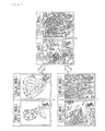
- FIG. 15 is a diagram illustrating a display example in a case where a query image and a similar image are compared to each other.
- FIG. 16 is a diagram illustrating a display example in a case where a query image and similar images are compared to each other.
- FIG. 17 is a diagram illustrating a display example in a case where a query image and similar images are compared to each other.
- FIG. 18 is a display example in a case where a query image and a similar image are concurrently scrolled.
- FIG. 19 is a display example in a case where a query image and a similar image are concurrently zoomed in.
- FIG. 20 is a diagram for describing center movement in a case where a query image and a similar image are concurrently zoomed in or out.
- FIG. 21 is a diagram illustrating center movement in the case where the query image and the similar image are concurrently zoomed in or out.
- FIG. 22 is a block diagram illustrating a configuration example of a computer.
- a similar case image display control unit as an embodiment of an information processing unit of the present disclosure is configured to present a diagnosed pathological image similar to a pathological image as a diagnostic target to a user (such as a pathologist) for comparison, when the pathological image as the diagnostic subject is observed.
- pathological image refers to an image obtained by scanning a prepared specimen (that is obtained by cutting a biopsy specimen from a body tissue, placing the biopsy specimen on a glass slide, and staining the biopsy specimen) that is generally observed by a diagnostician such as a pathologist under a microscope.
- the present disclosure is also applicable to a case where, in addition to the pathological image, a medical image obtained by picking up an image of a human body or the like by CT, MRI, X-rays, or the like, and an arbitrary image not limited to the medical field are presented.
- diagnosis image a pathological image obtained by scanning a prepared specimen as a diagnostic target
- case image a pathological image that has been diagnosed
- FIG. 1 illustrates a configuration example of the similar case image display control unit.
- This similar case image presentation unit 10 is configured of an operation input section 11 , a display control section 12 , a diagnostic image input section 13 , a query image setting section 14 , and a case image obtaining section 15 .
- the operation input section 11 accepts a diagnostic image selection operation by the user (such as a pathologist serving as a diagnostician), operations of movement or zooming in/out of a displayed diagnostic image, a setting operation of a query image provided on the diagnostic image, an input operation of a search condition (such as a keyword), and the like. Moreover, the operation input section 11 inputs an operation signal according to an input operation to the display control section 12 , the diagnostic image input section 13 , the query image setting section 14 , or the case image obtaining section 15 corresponding to the operation signal.
- a diagnostic image selection operation by the user such as a pathologist serving as a diagnostician
- operations of movement or zooming in/out of a displayed diagnostic image such as a pathologist serving as a diagnostician
- a setting operation of a query image provided on the diagnostic image an input operation of a search condition (such as a keyword)
- a search condition such as a keyword
- the display control section 12 displays a screen 50 ( FIG. 4 ) serving as a user interface on a display 30 in a following stage.
- a diagnostic image, a case image displayed as a search result, and the like are displayed in the screen 50 serving as the user interface. It is to be noted that a specific display example of the screen 50 will be described later.
- the diagnostic image input section 13 determines a diagnostic image serving as a diagnostic target from pathological images prepared in advance in response to an operation signal based on a selection operation by the user, and inputs the diagnostic image to the display control section 12 and the query image setting section 14 .
- the query image setting section 14 extracts, from the displayed diagnostic image, a region indicated by a query set frame 53 with a predetermined size set on the diagnostic image by the user, and inputs a resultant query image to the case image obtaining section 15 .
- the case image obtaining section 15 transmits the query image to a case search server 20 to request retrieval. At this time, the case image obtaining section 15 also supplies, to the case search server 20 , diagnostic image control information that indicates an operation history of the user relating to displaying of the diagnostic image, and secondary filtering information (both of which will be described later). Then, the case image obtaining section 15 obtains a case image obtained as a search result of the case search server 20 to supply the case image to the display control section 12 .
- the case search server 20 may be provided on, for example, the Internet. However, the entire case search server 20 or some of constituent components of the case search server 20 may be built in the similar case image presentation unit 10 .
- FIG. 2 illustrates a configuration example of the case search server 20 .
- the case search server 20 is configured of an image feature amount extraction section 21 , a case image search section 22 , a case database 23 , a case registration section 24 , a first filter section 25 , a second filter section 26 , and a search result output section 27 .
- the image feature amount extraction section 21 extracts an image feature amount from the query image to supply the image feature amount to the case image search section 22 .
- any existing method may be applied, as long as the method is in common with a method of extracting an image feature amount of a case image registered in the case database 23 that will be described below.
- a frequency feature of a texture of the query image may be extracted by FFT, or a histogram feature amount of a luminance gradient such as HOG and SHIFT feature amounts may be extracted.
- the extracted image feature amount may be represented by, for example, an N-dimensional vector.
- the case image search section 22 retrieves case images each of which includes a sub-image similar to the query image from the case database 23 , based on the image feature amount of the query image, and inputs search results thus obtained (not only image data but also entire case information including the image data) to the first filter section 25 .
- the sub-image, as a search result, similar to the query image on the case image is also referred to as “similar image”.
- the case database 23 holds a large number of case images that has been diagnosed. It is to be noted that a sub-image representing a region that is marked in diagnosis and has the same size as that of the query image is provided on the case image, and case information per sub-image is registered in the case database 23 . This sub-image on the case image may serve as a similar image in a following stage.
- FIG. 3 illustrates items included in the case information.
- the case information 40 corresponding to each sub-image includes an image ID 41 , image data 42 , sub-image position and size 43 , an image feature amount 44 , chart information 45 , diagnosis-time image control information 46 , and secondary filtering information 47 .
- the image ID 41 is identification information individually assigned to each of sub-images on case images.
- the image data 42 is image data representing each pixel value of the case image including the sub-image.
- the sub-image position and size 43 are information representing a position and a size of the sub-image in the case image.
- the image feature amount 44 is an image feature amount of the sub-image. It is to be noted that it is necessary to adopt a same method for an image feature amount extraction method to obtain the image feature amount 44 and an image feature amount extraction method of the image feature extraction section 21 .
- the chart information 45 is a character string representing a diagnosis result that has been already obtained of the case image including the sub-image.
- the diagnosis-time image control information 46 represents a display operation history of the user when the case image including the sub-image is diagnosed, and corresponds to diagnosis-time image control information 60 that will be described later.
- the secondary filtering information 47 is set by the user when the case image including the sub-image is diagnosed, and corresponds to secondary filtering information 70 that will be described later.
- the case registration section 24 registers case information for each of sub-images on case images in the case database 23 . It is to be noted that a diagnosis result of a diagnostic image diagnosed by the user with use of the similar case image presentation unit 10 may be registered in the case database 23 .
- the first filter section 25 performs primary filtering on the search results based on the image feature amount from the case image search section 22 , based on the diagnosis-time image control information.
- diagnosis-time image control information refers to information representing an operation history when an operation of display control such as movement (scrolling from side to side and up and down) and zooming in/out of the diagnostic image when the user makes a diagnosis.
- the diagnosis-time image control information will be described later referring to FIG. 6 .
- the second filter section 26 performs secondary filtering on primary filtering results by the first filter section 25 , based on secondary filtering information.
- the secondary filtering information is configured of items such as a keyword and sort criteria that are input by the user to narrow the primary filtering results.
- the secondary filtering information will be described later referring to FIG. 9 .
- the search result output section 27 outputs results (case images each of which includes a region serving as a similar image) of the secondary filtering by the second filter section 26 to the case image obtaining section 15 of the similar case image presentation unit 10 .
- FIG. 4 illustrates a display example of a screen serving as a user interface.
- This display screen 50 is displayed on the display 30 , based on control by the display control section 12 .
- a diagnostic image display region 51 , a list number setting region 54 , a keyword input region 55 , a sort order setting region 56 , and a search result display region 57 are included in the display screen 50 .
- the diagnostic image input from the diagnostic image input section 13 is displayed in the diagnostic image display region 51 .
- FIG. 5 that illustrates an enlarged view of the diagnostic image display region 51
- the entire diagnostic image is zoomed out and displayed at the lower right in the diagnostic image display region 51
- an zoom-in region 52 indicated in the entire diagnostic image represents a range that is zoomed in and displayed in the diagnostic image display region 51 .
- the user is allowed to arbitrarily scroll the diagnostic image displayed in the diagnostic image display region 51 , to zoom in or out the diagnostic image to an arbitrary magnification, and to rotate the diagnostic image.
- An operation history at this time is recorded at predetermined sampling intervals to generate diagnosis-time image control information.
- FIG. 6 illustrates an example of the diagnosis-time image control information.
- the diagnosis-time image control information 60 is configured of timings of sampling intervals, an X coordinate, a Y coordinate, and magnification.
- FIG. 6 indicates a case where the diagnostic image centering coordinates ( 330 , 456 ) is displayed under a magnification of 10 at timings t 1 and t 2 . Then, FIG. 6 indicates a case where, at a timing t 3 , the diagnostic image is scrolled to move a center thereof to coordinates ( 442 , 463 ), and is zoomed in and displayed under a magnification of 20. Then, FIG. 6 indicates a case where, at a timing t 4 , the diagnostic image is further zoomed in and displayed under a magnification of 40.
- the query image set frame 53 is allowed to be provided on the diagnostic image displayed in the diagnostic image display region 51 .
- the user is allowed to move the query image set frame 53 to an arbitrary position on the diagnostic image in the diagnostic image display region 51 .
- the region indicated by the query image set frame 53 on the diagnostic image serves as a query image.
- the user is allowed to set the number of systems (list number) of secondary filtering results obtained by further narrowing the primary filtering results.
- list number the number of systems (list number) of secondary filtering results obtained by further narrowing the primary filtering results.
- the list number is set to 2
- only two systems ( 55 - 1 and 55 - 2 ) of the keyword input region 55 are displayed.
- two systems of search results are displayed in the search result display region 57 .
- the user is allowed to select or directly input a keyword as one item of research result filtering information for further narrowing the primary filtering results.
- the keyword selected or directly input serves as a search word for the chart information 45 of the case information 40 .
- a keyword in a case where the diagnostic image is a pathological image of a stomach is illustrated, and in the keyword input region 55 - 1 , “Por” and “Sig” are selected as keywords.
- “Non Cancer” is selected as a keyword.
- the user is allowed to set criteria when the secondary filtering results are sorted.
- criteria in a case where the diagnostic image is a pathological image of the stomach are illustrated, and the sort criteria are set to “nucleus size”.
- FIG. 8A illustrates keywords and sort criteria in a case where the diagnostic image is a pathological image of a stomach.
- FIG. 8B illustrates keywords and sort criteria in a case where the diagnostic image is a pathological image of a prostate gland. It is to be noted that FIG. 8 illustrates only two examples in the cases where the diagnostic image is the pathological image of the stomach or prostate gland; however, as a matter of course, keywords and sort criteria corresponding to a case other than these cases may be prepared.
- FIG. 9 illustrates items of secondary filtering information generated depending on setting of the keyword input region 55 and the sort order setting region 56 .
- the secondary filtering information 70 includes a filtering keyword 71 , sort criteria 72 , a similar image ID 73 , and case image control information 74 .
- the filtering keyword 71 is a keyword selected or directly input in the keyword input region 55 , and is a search word used to narrow the primary filtering results, based on the chart information 45 of the case information 40 .
- the sort criteria 72 indicate criteria set in the sort order setting region 56 .
- the similar image ID 73 is identification information of a search result (a similar image) to which the user refers in search results (similar images) displayed in the search result display region 57 .
- the case image control information 74 is information representing an operation history when the similar image indicated by the similar image ID 73 is displayed for reference for the user.
- search result display region 57 secondary filtering results based on the secondary filtering information including the keyword set or directly input in the keyword input region 55 are sorted according to the sort criteria set in the sort order setting region 56 , and the sorted secondary filtering results are displayed.
- FIG. 10 illustrates a display example in a case where the list number is set to 1 in the list number setting region 54 , all keywords are selected in the keyword input region 55 , and image feature amount similarity is set as sort criteria in the sort order setting region 56 .
- FIG. 11 illustrates a display example in a case where the list number is set to 2 in the list number setting region 54 , all keywords except for “Not Cancer” are selected in the keyword input region 55 - 1 , “Not Cancer” is selected in the keyword input region 55 - 2 , and angle-of-view feature amount similarity is set as sort criteria in the sort order setting region 56 .
- case images of various cancers similar to the diagnostic image and non-cancer case images are allowed to be displayed as search results.
- FIG. 12 illustrates a display example in a case where the list number is set to 3 in the list number setting region 54 , “Tub 2 ”, “Por”, and “Sig” are selected in the keyword input regions 55 - 1 , 55 - 2 , and 55 - 3 , respectively, and angle-of-view feature amount similarity is set as sort criteria in the sort order setting region 56 .
- case images of respective suspected cases for the diagnostic image are allowed to be displayed in respective columns.
- a settable list number in the list number setting region 54 may be 4 or more.
- FIG. 13 is a flow chart describing a similar case image presenting process by the similar case image presentation unit 10 .
- step S 1 the diagnostic image input section 13 determines a diagnostic image as a diagnostic target from prepared pathological images in response to an operation signal based on a selection operation by the user input from the operation input section 11 to input the diagnostic image to the display control section 12 and the query image setting section 14 .
- the display control section 12 allows the diagnostic image to be displayed on the display. At this time, when the user scrolls or zooms in or out the diagnostic image, a history of such an operation is stored as diagnosis-time image control information.
- step S 2 the query image setting section 14 extracts, as a query image, a region in the query image set frame 53 set by the user on the displayed diagnostic image, and inputs the query image to the case image obtaining section 15 .
- the case image obtaining section 15 transmits the query image to the case search server 20 to request retrieval.
- step S 3 the image feature amount extraction section 21 of the case search server 20 extracts the image feature amount from the query image to supply the image feature amount to the case image search section 22 .
- step S 4 the case image search section 22 retrieves a case image including a sub-image similar to the query image from the case database 23 , based on the image feature amount of the query image. More specifically, similarity between the image feature amount of the query image and the image feature amount 44 of the case information 40 is calculated with use of, for example, the following expression (1). Then, a predetermined number of case images are detected in descending order of similarity, or case images with higher similarity than a predetermined threshold value are detected, and the case images are input to the first filter section 25 as search results.
- N represents the number of dimensions of a feature amount
- Q represents a feature amount of the query image
- D represents a feature amount of an image in the case database
- w represents weight parameters for respective feature dimensions. All of the weight parameters for the respective feature dimensions may be, for example, 1, or distance metric learning in a feature space relating to similarity may be performed by a known technique, and a value obtained by the learning may be applied to the weight parameters for the respective feature dimensions.
- a similarity calculation method is not limited to the expression (1), and any method may be used.
- step S 5 the first filter section 25 performs primary filtering on each case information 40 retrieved as information similar in the image feature amount to the query image, based on the diagnosis-time image control information. More specifically, similarity between the diagnosis-time image control information of the diagnostic image and the diagnosis-time image control information 46 of each case information 40 (diagnosis-time image control information when the case image is diagnosed) is calculated. Then, a predetermined number of pieces of case information 40 are detected in descending order of similarity, or pieces of case information 40 with higher similarity than a predetermined threshold value are detected, and the pieces of the case information 40 are input to the second filter section 26 as primary filtering results.
- FIG. 14 describes a method of determining similarity by focusing attention on change in an X coordinate value of the diagnosis-time image control information.
- time of the diagnosis-time image control information and a coordinate value of a pixel are converted into relative values.
- relative time to total time taken for diagnosis and relative coordinates obtained assuming that an image size is 1000 pixels are calculated.
- an expression using the Bhattacharyya distance represented by the following expression (2) may be adopted, where diagnosis time is t, and the two graphs are p(t) and q(t).
- each of the plurality of similarities may be subjected to threshold value processing, and the processed similarities may be used as results of filtering, or the plurality of similarities integrated with use of the following expression (3) may be used.
- S c ⁇ S x + ⁇ S y + ⁇ S m (3)
- S x , S y , and S m are similarities focused on the X coordinate value, the Y coordinate value, and the display magnification of diagnosis-time image control information, respectively, and ⁇ , ⁇ , and ⁇ are weight parameters for them.
- All of the weight parameters for respective feature dimensions may be, for example, 1, or distance metric learning in a feature space relating to similarity may be performed by a known technique, and a value obtained by the learning may be applied to the weight parameters for the respective feature dimensions.
- step S 6 the second filter section 26 performs secondary filtering on the primary filtering results, based on secondary filtering information. More specifically, chart information 45 included in the case information 40 of the primary filtering results is retrieved with use of a keyword (a filtering keyword 71 ) set in the keyword input region 55 of the screen 50 as a search word to narrow the primary filtering results, or results narrowed by the keyword are sorted, based on sort criteria (sort criteria 72 ) set by the sort order setting region 56 .
- a keyword a filtering keyword 71
- similarity between the case image control information 74 of the secondary filtering information 70 and the diagnosis-time image control information 46 of the primary filtering result may be calculated in a method similar to the primary filtering, and narrowing may be performed, based on the calculated similarity.
- step S 7 the search result output section 27 outputs secondary filtering results (case images each of which includes a region serving as a similar image) by the second filter section 26 to the case image obtaining section 15 of the similar case image presentation unit 10 .
- the case image obtaining section 15 supplies the case images as search results responded from the case search server 20 to the display control section 12 .
- the display control section 12 displays a screen as a user interface including the case images as the research results on the display 30 . More specifically, the screen 50 as illustrated in FIGS. 10 to 12 is displayed according to the setting number in the list number setting region 54 of the screen 50 . Thus, description of the similar case image presenting process is completed.
- all keywords may be selected in the keyword input region 55 - 1 .
- search results based on similarity of the image feature amount are displayed on the search result display region 57 , based on sort criteria (the image feature amount similarity in a case in FIG. 10 ).
- the display 40 displays a screen 60 in which the query image on the diagnostic image and the similar image on the selected case image are displayed side by side. Therefore, the user is allowed to closely compare the query image and the similar image that are zoomed in and displayed to each other.
- the list number is set to 2 in the list number setting region 54 , and all keywords other than “Not Cancer” may be selected in the keyword input region 55 - 1 , and “Not Cancer” may be selected in the keyword input region 55 - 2 .
- the display 30 displays a screen in which the similar image on the selected cancer case image, the query image on the diagnostic image, and the similar image on the selected non-cancer case image are displayed side by side.
- the user is allowed to closely compare the query image that is zoomed in and displayed in a center of the screen to the cancer similar image and the non-cancer similar image that are zoomed in and displayed on both sides of the query image
- a primary purpose of pathological image diagnosis is mainly to determine whether or not a lesion is included in the diagnostic image; therefore, as illustrated in FIG. 11 , it may be expected that displaying of a group of lesion (cancer) case images similar to the query image and a group of non-lesion (non-cancer) case images similar to the query image together with the query image is extremely useful in diagnosis.
- the user is allowed to easily diagnose whether the query image is similar to a group with a lesion or a group without lesion by comparison.
- FIG. 18 illustrates a state in which, in a case where one of the query image and the similar image that are displayed side by side in the screen 60 illustrated in FIG. 15 is scroll-displayed, the other of them is also scroll-displayed accordingly. Comparison with a corresponding region is easily made by scroll-displaying one of the query image and the similar image and also scroll-displaying the other of them accordingly; therefore, this contributes to an improvement in diagnosis efficiency of the user.
- FIG. 19 illustrates a state in which, in a case where one of the query image and the similar image that are displayed side by side in the screen 60 illustrated in FIG. 15 is zoomed in, the other of them is also zoomed in accordingly. Comparison with a corresponding region is easily made by zooming in or out one of the query image and the similar image and also zooming in or out the other of them accordingly; therefore, this contributes to an improvement in diagnosis efficiency of the user.
- FIG. 18 and FIG. 19 illustrate a case where one similar image is displayed for one query image; however, even in a case where two or more similar images are displayed for one query image, in response to scroll-displaying or zooming in or out of one image of the two or more similar images and the query image the other images of them may be also scroll-displayed or zoomed in or out accordingly.
- FIG. 20 and FIG. 21 are diagrams for describing movement of a center point in a case where, in response to zooming in or out of one of the query image and the similar image, the other of them is also zoomed in or out accordingly.
- a in FIG. 20 illustrates a state in which the magnifications of the query image and the similar image are decreased to display the entire diagnostic image and the entire case image
- B in FIG. 20 illustrates a state in which the query image and the similar image are displayed
- C in FIG. 20 illustrates a state in which the query image and the similar image are zoomed in and displayed.
- FIG. 21 illustrates movement of a center of a region that is to be zoomed in when one of the query image and the similar image is zoomed in and the other of them is also zoomed in.
- magnifications of the query image and the similar image are controlled to be decreased using, as center points, not centers of the query image and the similar image but centers of the diagnostic image including the query image and the case image including the similar image.
- magnifications of the query image and the similar image are controlled to be increased using, as center points, not the centers of the diagnostic image as a base of the query image and the case image as a base of the similar image but the centers of the query image and the similar image.
- the magnifications of the query image and the similar image are controlled to be increased using, as center points, the centers of the query image and the similar image.
- the magnifications of the query image and the similar image are controlled to be decreased using, as center points, the centers of the query image and the similar image.
- diagnosis efficiency by image comparison of the user is allowed to be improved by moving the center points in a case where, in response to zooming in or out of one of the query image and the similar image, the other of them is also zoomed in or out accordingly.
- the above-described processes are allowed to be executed by hardware or software.
- a program forming the software is installed into a computer.
- the computer used herein may include a computer mounted in dedicated hardware, and a general-purpose personal computer capable of executing various functions by installing various programs into the computer.
- FIG. 22 is a block diagram illustrating a configuration example of hardware of a computer that executes the above-described processes with use of a program.
- a CPU Central Processing Unit
- ROM Read Only Memory
- RAM Random Access Memory
- An input/output interface 205 is further connected to the bus 204 .
- An input section 206 , an output section 207 , a storage section 208 , a communication section 209 , and a drive 210 are connected to the input/output interface 205 .
- the input section 206 may be configured of a keyboard, a mouse, a microphone, and the like.
- the output section 207 may be configured of a display, a speaker, and the like.
- the storage section 208 may be configured of a hard disk, a nonvolatile memory, and the like.
- the communication section 209 may be configured of a network interface and the like.
- the drive 210 may drive a removable medium 211 such as a magnetic disk, an optical disk, a magneto-optical disk, or a semiconductor memory.
- the program that is executed by the computer 200 may be provided as a so-called web application that is allowed to be obtained and executed by accessing a predetermined server on the Internet.
- the program is allowed to be installed into the storage section 208 through the input/output interface 205 by mounting the removable medium 211 into the drive 210 . Further, the program is allowed to be received by the communication section 209 through a wired or wireless transmission medium, and then be installed into the storage section 208 . In addition, the program is allowed to be installed into the ROM 202 or the storage section 208 in advance.
- the program that is executed by the computer 200 may be a program in which processes are performed time-sequentially in the order described in the description or a program in which processes are performed concurrently or at a necessary timing such as when a call is made.
Landscapes
- Engineering & Computer Science (AREA)
- Theoretical Computer Science (AREA)
- Physics & Mathematics (AREA)
- General Physics & Mathematics (AREA)
- Data Mining & Analysis (AREA)
- General Engineering & Computer Science (AREA)
- Databases & Information Systems (AREA)
- Health & Medical Sciences (AREA)
- General Health & Medical Sciences (AREA)
- Library & Information Science (AREA)
- Computer Vision & Pattern Recognition (AREA)
- Medical Informatics (AREA)
- Radiology & Medical Imaging (AREA)
- Nuclear Medicine, Radiotherapy & Molecular Imaging (AREA)
- Multimedia (AREA)
- Life Sciences & Earth Sciences (AREA)
- Software Systems (AREA)
- Quality & Reliability (AREA)
- Primary Health Care (AREA)
- Public Health (AREA)
- Mathematical Physics (AREA)
- Epidemiology (AREA)
- Bioinformatics & Computational Biology (AREA)
- Bioinformatics & Cheminformatics (AREA)
- Evolutionary Biology (AREA)
- Artificial Intelligence (AREA)
- Evolutionary Computation (AREA)
- Biomedical Technology (AREA)
- Molecular Biology (AREA)
- Computational Linguistics (AREA)
- Human Computer Interaction (AREA)
- Measuring And Recording Apparatus For Diagnosis (AREA)
- Information Retrieval, Db Structures And Fs Structures Therefor (AREA)
- Medical Treatment And Welfare Office Work (AREA)
- Processing Or Creating Images (AREA)
Applications Claiming Priority (3)
| Application Number | Priority Date | Filing Date | Title |
|---|---|---|---|
| JP2012283035A JP2014127011A (ja) | 2012-12-26 | 2012-12-26 | 情報処理装置、情報処理方法、およびプログラム |
| JP2012-283035 | 2012-12-26 | ||
| PCT/JP2013/082807 WO2014103664A1 (ja) | 2012-12-26 | 2013-12-06 | 情報処理装置、情報処理方法、およびプログラム |
Related Parent Applications (1)
| Application Number | Title | Priority Date | Filing Date |
|---|---|---|---|
| PCT/JP2013/082807 A-371-Of-International WO2014103664A1 (ja) | 2012-12-26 | 2013-12-06 | 情報処理装置、情報処理方法、およびプログラム |
Related Child Applications (1)
| Application Number | Title | Priority Date | Filing Date |
|---|---|---|---|
| US15/695,456 Continuation US11010375B2 (en) | 2012-12-26 | 2017-09-05 | Information processing unit, information processing method, and program |
Publications (2)
| Publication Number | Publication Date |
|---|---|
| US20150347505A1 US20150347505A1 (en) | 2015-12-03 |
| US9798770B2 true US9798770B2 (en) | 2017-10-24 |
Family
ID=51020756
Family Applications (2)
| Application Number | Title | Priority Date | Filing Date |
|---|---|---|---|
| US14/652,581 Active 2034-10-09 US9798770B2 (en) | 2012-12-26 | 2013-12-06 | Information processing unit, information processing method, and program |
| US15/695,456 Active 2034-12-19 US11010375B2 (en) | 2012-12-26 | 2017-09-05 | Information processing unit, information processing method, and program |
Family Applications After (1)
| Application Number | Title | Priority Date | Filing Date |
|---|---|---|---|
| US15/695,456 Active 2034-12-19 US11010375B2 (en) | 2012-12-26 | 2017-09-05 | Information processing unit, information processing method, and program |
Country Status (5)
| Country | Link |
|---|---|
| US (2) | US9798770B2 (de) |
| EP (1) | EP2940597B1 (de) |
| JP (1) | JP2014127011A (de) |
| CN (1) | CN104885079B (de) |
| WO (1) | WO2014103664A1 (de) |
Cited By (1)
| Publication number | Priority date | Publication date | Assignee | Title |
|---|---|---|---|---|
| US12327626B2 (en) | 2019-12-17 | 2025-06-10 | Fujifilm Corporation | Diagnosis support device, diagnosis support method, and diagnosis support program |
Families Citing this family (28)
| Publication number | Priority date | Publication date | Assignee | Title |
|---|---|---|---|---|
| JPS6180878A (ja) * | 1984-09-28 | 1986-04-24 | Hitachi Ltd | 超電導マグネツト用クライオスタツト |
| JP5677348B2 (ja) * | 2012-03-23 | 2015-02-25 | 富士フイルム株式会社 | 症例検索装置、症例検索方法及びプログラム |
| US10216762B2 (en) * | 2014-06-04 | 2019-02-26 | Panasonic Corporation | Control method and non-transitory computer-readable recording medium for comparing medical images |
| KR102289393B1 (ko) * | 2014-07-11 | 2021-08-13 | 삼성메디슨 주식회사 | 영상 장치 및 그 제어방법 |
| JP5905546B2 (ja) * | 2014-08-28 | 2016-04-20 | 京セラ株式会社 | 電子機器 |
| US10318575B2 (en) | 2014-11-14 | 2019-06-11 | Zorroa Corporation | Systems and methods of building and using an image catalog |
| JP6419560B2 (ja) * | 2014-12-05 | 2018-11-07 | 株式会社東芝 | 検索装置、方法及びプログラム |
| JP6482261B2 (ja) * | 2014-12-10 | 2019-03-13 | オリンパス株式会社 | 画像検索装置、画像検索方法及び画像検索プログラム |
| JP6836994B2 (ja) * | 2015-01-31 | 2021-03-03 | エフ.ホフマン−ラ ロシュ アーゲーF. Hoffmann−La Roche Aktiengesellschaft | メソダイセクションのためのシステム及び方法 |
| JP2017041022A (ja) * | 2015-08-18 | 2017-02-23 | キヤノン株式会社 | 情報処理装置、情報処理方法及びプログラム |
| JP6675099B2 (ja) * | 2015-09-30 | 2020-04-01 | パナソニックIpマネジメント株式会社 | 制御方法及びプログラム |
| CN105740378B (zh) * | 2016-01-27 | 2020-07-21 | 北京航空航天大学 | 一种数字病理全切片图像检索方法 |
| JP6333871B2 (ja) * | 2016-02-25 | 2018-05-30 | ファナック株式会社 | 入力画像から検出した対象物を表示する画像処理装置 |
| JP2016154023A (ja) * | 2016-03-16 | 2016-08-25 | 京セラ株式会社 | 電子機器 |
| CN106021362B (zh) * | 2016-05-10 | 2018-04-13 | 百度在线网络技术(北京)有限公司 | 查询式的图片特征表示的生成、图片搜索方法和装置 |
| US11468111B2 (en) * | 2016-06-01 | 2022-10-11 | Microsoft Technology Licensing, Llc | Online perspective search for 3D components |
| US10467257B2 (en) | 2016-08-09 | 2019-11-05 | Zorroa Corporation | Hierarchical search folders for a document repository |
| US10311112B2 (en) * | 2016-08-09 | 2019-06-04 | Zorroa Corporation | Linearized search of visual media |
| US10664514B2 (en) | 2016-09-06 | 2020-05-26 | Zorroa Corporation | Media search processing using partial schemas |
| JP6885896B2 (ja) * | 2017-04-10 | 2021-06-16 | 富士フイルム株式会社 | 自動レイアウト装置および自動レイアウト方法並びに自動レイアウトプログラム |
| KR102192164B1 (ko) * | 2018-08-08 | 2020-12-16 | 주식회사 딥바이오 | 생체 이미지 진단 시스템, 생체 이미지 진단 방법, 및 이를 수행하기 위한 단말 |
| JP7239363B2 (ja) * | 2019-03-22 | 2023-03-14 | ソニー・オリンパスメディカルソリューションズ株式会社 | 医療用画像処理装置、医療用観察装置、医療用観察システム、医療用画像処理装置の作動方法および医療用画像処理プログラム |
| CN114375477B (zh) | 2019-06-07 | 2026-03-17 | 徕卡显微系统Cms有限公司 | 用于处理生物学相关数据的系统和方法、用于控制显微镜的系统和方法及显微镜 |
| JP2021173734A (ja) * | 2020-04-30 | 2021-11-01 | ソニーグループ株式会社 | 生成装置、生成方法、生成プログラム及び診断支援システム |
| JP7650036B2 (ja) | 2020-10-15 | 2025-03-24 | ビュノ インコーポレイテッド | 画像解析のためのユーザーインターフェース |
| JP2024061696A (ja) * | 2021-03-24 | 2024-05-08 | ソニーグループ株式会社 | 医療用画像解析装置、医療用画像解析方法及び医療用画像解析システム |
| WO2024024797A1 (ja) * | 2022-07-29 | 2024-02-01 | コニカミノルタ株式会社 | 画像管理システム、画像管理装置、画像管理方法及び画像管理プログラム |
| WO2024194921A1 (ja) | 2023-03-17 | 2024-09-26 | 日本電気株式会社 | 病理診断支援装置、病理診断支援方法、及び、記録媒体 |
Citations (16)
| Publication number | Priority date | Publication date | Assignee | Title |
|---|---|---|---|---|
| US20020019751A1 (en) * | 2000-06-22 | 2002-02-14 | Radvault, Inc. | Medical image management system and method |
| US20030013951A1 (en) * | 2000-09-21 | 2003-01-16 | Dan Stefanescu | Database organization and searching |
| JP2004005364A (ja) | 2002-04-03 | 2004-01-08 | Fuji Photo Film Co Ltd | 類似画像検索システム |
| US6904163B1 (en) * | 1999-03-19 | 2005-06-07 | Nippon Telegraph And Telephone Corporation | Tomographic image reading method, automatic alignment method, apparatus and computer readable medium |
| JP2007286945A (ja) | 2006-04-18 | 2007-11-01 | Fujifilm Corp | 類似画像検索装置および方法並びにプログラム |
| US20080075348A1 (en) * | 2006-09-21 | 2008-03-27 | Dan Rappaport | Medical image analysis |
| US20080243395A1 (en) | 2007-03-30 | 2008-10-02 | Fujifilm Corporation | Image diagnosis supporting apparatus and system |
| US20090080734A1 (en) * | 2006-04-19 | 2009-03-26 | Fujifim Corporation | Diagnosis support system |
| US20100076921A1 (en) | 2008-09-24 | 2010-03-25 | Fuji Xerox Co., Ltd. | Similar image providing device, method and program storage medium |
| US20100226550A1 (en) * | 2009-01-14 | 2010-09-09 | Canon Kabushiki Kaisha | Information processing apparatus and information processing method |
| US20110122138A1 (en) * | 2006-08-28 | 2011-05-26 | Guenter Schmidt | Context driven image mining to generate image-based biomarkers |
| US20120063663A1 (en) * | 2010-09-15 | 2012-03-15 | Toshiba Medical Systems Corporation | Medical image processing apparatus and medical image processing method |
| JP2012059251A (ja) | 2010-08-11 | 2012-03-22 | Toshiba Corp | レポート作成支援システム |
| US20120134550A1 (en) * | 2010-11-26 | 2012-05-31 | General Electric Company | Systems and methods for comparing different medical images to analyze a structure-of-interest |
| US20120327211A1 (en) * | 2010-03-03 | 2012-12-27 | Olympus Corporation | Diagnostic information distribution device and pathology diagnosis system |
| US20130254187A1 (en) * | 2012-03-23 | 2013-09-26 | Fujifilm Corporation | Device, method, and non-transitory computer-readable medium for searching database |
Family Cites Families (16)
| Publication number | Priority date | Publication date | Assignee | Title |
|---|---|---|---|---|
| WO2003017833A1 (en) * | 2001-08-31 | 2003-03-06 | Jong-Won Park | Method and apparatus for a medical image processing system |
| JP4528529B2 (ja) * | 2004-01-20 | 2010-08-18 | 株式会社東芝 | 超音波診断装置及び超音波画像データ処理方法 |
| JP2005218796A (ja) * | 2004-02-09 | 2005-08-18 | Matsushita Electric Ind Co Ltd | 医用画像処理装置および医用画像処理方法 |
| WO2007023522A1 (ja) * | 2005-08-22 | 2007-03-01 | National Center Of Neurology And Psychiatry | 脳疾患の診断支援方法及び装置 |
| CA2632040C (en) * | 2005-11-30 | 2014-09-16 | Nihon Medi-Physics Co., Ltd. | Neurodegenerative disease detection method, detecting program, and detector |
| US8090172B2 (en) * | 2007-09-12 | 2012-01-03 | Siemens Medical Solutions Usa, Inc. | Robust segmentation of breast and muscle in MRI |
| US8392053B2 (en) * | 2007-12-13 | 2013-03-05 | Service Solutions U.S., Llc | Graphing device and method |
| JP5203858B2 (ja) * | 2008-09-01 | 2013-06-05 | 富士フイルム株式会社 | 医用画像表示装置、医用画像表示方法、並びに医用画像表示プログラム |
| JP5227911B2 (ja) * | 2009-07-22 | 2013-07-03 | 株式会社日立国際電気 | 監視映像検索装置及び監視システム |
| JP2011092681A (ja) * | 2009-09-30 | 2011-05-12 | Fujifilm Corp | 医用画像処理装置および方法並びにプログラム |
| US8799013B2 (en) * | 2009-11-24 | 2014-08-05 | Penrad Technologies, Inc. | Mammography information system |
| US20110238676A1 (en) * | 2010-03-25 | 2011-09-29 | Palm, Inc. | System and method for data capture, storage, and retrieval |
| JP5551957B2 (ja) * | 2010-03-31 | 2014-07-16 | 富士フイルム株式会社 | 投影画像生成装置およびその作動方法、並びに投影画像生成プログラム |
| JP5701138B2 (ja) * | 2011-04-19 | 2015-04-15 | 富士フイルム株式会社 | 医用画像処理装置および方法、並びにプログラム |
| KR101982149B1 (ko) * | 2011-09-05 | 2019-05-27 | 삼성전자주식회사 | 의료 영상의 일부 정보를 활용한 장기 영상 생성 방법 및 장치 |
| SG11201407749TA (en) * | 2012-05-24 | 2014-12-30 | Hitachi Ltd | Image analysis device, image analysis system, and image analysis method |
-
2012
- 2012-12-26 JP JP2012283035A patent/JP2014127011A/ja active Pending
-
2013
- 2013-12-06 CN CN201380067324.0A patent/CN104885079B/zh active Active
- 2013-12-06 EP EP13868702.5A patent/EP2940597B1/de active Active
- 2013-12-06 WO PCT/JP2013/082807 patent/WO2014103664A1/ja not_active Ceased
- 2013-12-06 US US14/652,581 patent/US9798770B2/en active Active
-
2017
- 2017-09-05 US US15/695,456 patent/US11010375B2/en active Active
Patent Citations (16)
| Publication number | Priority date | Publication date | Assignee | Title |
|---|---|---|---|---|
| US6904163B1 (en) * | 1999-03-19 | 2005-06-07 | Nippon Telegraph And Telephone Corporation | Tomographic image reading method, automatic alignment method, apparatus and computer readable medium |
| US20020019751A1 (en) * | 2000-06-22 | 2002-02-14 | Radvault, Inc. | Medical image management system and method |
| US20030013951A1 (en) * | 2000-09-21 | 2003-01-16 | Dan Stefanescu | Database organization and searching |
| JP2004005364A (ja) | 2002-04-03 | 2004-01-08 | Fuji Photo Film Co Ltd | 類似画像検索システム |
| JP2007286945A (ja) | 2006-04-18 | 2007-11-01 | Fujifilm Corp | 類似画像検索装置および方法並びにプログラム |
| US20090080734A1 (en) * | 2006-04-19 | 2009-03-26 | Fujifim Corporation | Diagnosis support system |
| US20110122138A1 (en) * | 2006-08-28 | 2011-05-26 | Guenter Schmidt | Context driven image mining to generate image-based biomarkers |
| US20080075348A1 (en) * | 2006-09-21 | 2008-03-27 | Dan Rappaport | Medical image analysis |
| US20080243395A1 (en) | 2007-03-30 | 2008-10-02 | Fujifilm Corporation | Image diagnosis supporting apparatus and system |
| US20100076921A1 (en) | 2008-09-24 | 2010-03-25 | Fuji Xerox Co., Ltd. | Similar image providing device, method and program storage medium |
| US20100226550A1 (en) * | 2009-01-14 | 2010-09-09 | Canon Kabushiki Kaisha | Information processing apparatus and information processing method |
| US20120327211A1 (en) * | 2010-03-03 | 2012-12-27 | Olympus Corporation | Diagnostic information distribution device and pathology diagnosis system |
| JP2012059251A (ja) | 2010-08-11 | 2012-03-22 | Toshiba Corp | レポート作成支援システム |
| US20120063663A1 (en) * | 2010-09-15 | 2012-03-15 | Toshiba Medical Systems Corporation | Medical image processing apparatus and medical image processing method |
| US20120134550A1 (en) * | 2010-11-26 | 2012-05-31 | General Electric Company | Systems and methods for comparing different medical images to analyze a structure-of-interest |
| US20130254187A1 (en) * | 2012-03-23 | 2013-09-26 | Fujifilm Corporation | Device, method, and non-transitory computer-readable medium for searching database |
Non-Patent Citations (1)
| Title |
|---|
| Aug. 5, 2016 EP communication issued for related EP application No. 13868702.5. |
Cited By (1)
| Publication number | Priority date | Publication date | Assignee | Title |
|---|---|---|---|---|
| US12327626B2 (en) | 2019-12-17 | 2025-06-10 | Fujifilm Corporation | Diagnosis support device, diagnosis support method, and diagnosis support program |
Also Published As
| Publication number | Publication date |
|---|---|
| EP2940597A1 (de) | 2015-11-04 |
| US20150347505A1 (en) | 2015-12-03 |
| JP2014127011A (ja) | 2014-07-07 |
| CN104885079A (zh) | 2015-09-02 |
| US11010375B2 (en) | 2021-05-18 |
| EP2940597A4 (de) | 2016-09-07 |
| WO2014103664A1 (ja) | 2014-07-03 |
| US20180004806A1 (en) | 2018-01-04 |
| CN104885079B (zh) | 2020-06-05 |
| EP2940597B1 (de) | 2019-11-13 |
Similar Documents
| Publication | Publication Date | Title |
|---|---|---|
| US9798770B2 (en) | Information processing unit, information processing method, and program | |
| US20200320336A1 (en) | Control method and recording medium | |
| US11158419B2 (en) | Control method and non-transitory computer-readable recording medium | |
| US10261681B2 (en) | Method for displaying a medical image and a plurality of similar medical images obtained from a case search system | |
| US10262189B2 (en) | Evaluation of co-registered images of differently stained tissue slices | |
| US20210133231A1 (en) | Control method and non-transitory computer-readable recording medium for comparing medical images | |
| CN104981798B (zh) | 生物标志表达的选择和显示 | |
| US8929627B2 (en) | Examination information display device and method | |
| US9875256B2 (en) | Control method of information terminal and recording medium | |
| US20130093781A1 (en) | Examination information display device and method | |
| EP2894599A1 (de) | Informationsverarbeitungsvorrichtung, informationsverarbeitungsverfahren und programm | |
| JP2012155455A (ja) | 画像処理装置および方法、並びにプログラム | |
| JP6373359B2 (ja) | 赤血球の分析のためのグラフィカル・ユーザ・インターフェース | |
| EP2235652B2 (de) | Navigation in einer bildserie | |
| KR101203047B1 (ko) | 뇌 자기공명영상 기반의 정량 분석 시스템 | |
| Farhidzadeh et al. | Signal intensity analysis of ecological defined habitat in soft tissue sarcomas to predict metastasis development | |
| US20140285503A1 (en) | Image display method, apparatus, and program | |
| CN120431406A (zh) | 基于强化学习和bi-rads指南的超声图像识别方法 | |
| JP2019519794A (ja) | サンプルの画像の中の、生体要素のうち少なくとも1つの関心ある要素の判別を支援するための方法及び電子デバイス、関連するコンピュータプログラム | |
| JP2014050457A (ja) | 画像処理装置及び領域抽出方法 |
Legal Events
| Date | Code | Title | Description |
|---|---|---|---|
| AS | Assignment |
Owner name: SONY CORPORATION, JAPAN Free format text: ASSIGNMENT OF ASSIGNORS INTEREST;ASSIGNORS:OHASHI, TAKESHI;YOKONO, JUN;NARIHIRA, TAKUYA;SIGNING DATES FROM 20150521 TO 20150601;REEL/FRAME:035845/0658 |
|
| AS | Assignment |
Owner name: JAPANESE FOUNDATION FOR CANCER RESEARCH, JAPAN Free format text: CORRECTIVE ASSIGNMENT TO CORRECT TO ADD SECOND ASSIGNEE NAME PREVIOUSLY RECORDED AT REEL: 035845 FRAME: 0658. ASSIGNOR(S) HEREBY CONFIRMS THE ASSIGNMENT;ASSIGNORS:OHASHI, TAKESHI;YOKONO, JUN;NARIHIRA, TAKUYA;SIGNING DATES FROM 20150521 TO 20150601;REEL/FRAME:035931/0901 Owner name: SONY CORPORATION, JAPAN Free format text: CORRECTIVE ASSIGNMENT TO CORRECT TO ADD SECOND ASSIGNEE NAME PREVIOUSLY RECORDED AT REEL: 035845 FRAME: 0658. ASSIGNOR(S) HEREBY CONFIRMS THE ASSIGNMENT;ASSIGNORS:OHASHI, TAKESHI;YOKONO, JUN;NARIHIRA, TAKUYA;SIGNING DATES FROM 20150521 TO 20150601;REEL/FRAME:035931/0901 |
|
| STCF | Information on status: patent grant |
Free format text: PATENTED CASE |
|
| MAFP | Maintenance fee payment |
Free format text: PAYMENT OF MAINTENANCE FEE, 4TH YEAR, LARGE ENTITY (ORIGINAL EVENT CODE: M1551); ENTITY STATUS OF PATENT OWNER: LARGE ENTITY Year of fee payment: 4 |
|
| MAFP | Maintenance fee payment |
Free format text: PAYMENT OF MAINTENANCE FEE, 8TH YEAR, LARGE ENTITY (ORIGINAL EVENT CODE: M1552); ENTITY STATUS OF PATENT OWNER: LARGE ENTITY Year of fee payment: 8 |