US9837765B2 - Apparatus for ejecting at least one integrated circuit card - Google Patents
Apparatus for ejecting at least one integrated circuit card Download PDFInfo
- Publication number
- US9837765B2 US9837765B2 US14/750,028 US201514750028A US9837765B2 US 9837765 B2 US9837765 B2 US 9837765B2 US 201514750028 A US201514750028 A US 201514750028A US 9837765 B2 US9837765 B2 US 9837765B2
- Authority
- US
- United States
- Prior art keywords
- tray
- electric
- switch
- push member
- contact element
- Prior art date
- Legal status (The legal status is an assumption and is not a legal conclusion. Google has not performed a legal analysis and makes no representation as to the accuracy of the status listed.)
- Expired - Fee Related
Links
Images




Classifications
-
- H—ELECTRICITY
- H01—ELECTRIC ELEMENTS
- H01R—ELECTRICALLY-CONDUCTIVE CONNECTIONS; STRUCTURAL ASSOCIATIONS OF A PLURALITY OF MUTUALLY-INSULATED ELECTRICAL CONNECTING ELEMENTS; COUPLING DEVICES; CURRENT COLLECTORS
- H01R13/00—Details of coupling devices of the kinds covered by groups H01R12/70 or H01R24/00 - H01R33/00
- H01R13/62—Means for facilitating engagement or disengagement of coupling parts or for holding them in engagement
- H01R13/629—Additional means for facilitating engagement or disengagement of coupling parts, e.g. aligning or guiding means, levers, gas pressure electrical locking indicators, manufacturing tolerances
- H01R13/633—Additional means for facilitating engagement or disengagement of coupling parts, e.g. aligning or guiding means, levers, gas pressure electrical locking indicators, manufacturing tolerances for disengagement only
- H01R13/6335—Additional means for facilitating engagement or disengagement of coupling parts, e.g. aligning or guiding means, levers, gas pressure electrical locking indicators, manufacturing tolerances for disengagement only comprising a handle
-
- G—PHYSICS
- G06—COMPUTING OR CALCULATING; COUNTING
- G06K—GRAPHICAL DATA READING; PRESENTATION OF DATA; RECORD CARRIERS; HANDLING RECORD CARRIERS
- G06K7/00—Methods or arrangements for sensing record carriers, e.g. for reading patterns
- G06K7/0013—Methods or arrangements for sensing record carriers, e.g. for reading patterns by galvanic contacts, e.g. card connectors for ISO-7816 compliant smart cards or memory cards, e.g. SD card readers
- G06K7/0021—Methods or arrangements for sensing record carriers, e.g. for reading patterns by galvanic contacts, e.g. card connectors for ISO-7816 compliant smart cards or memory cards, e.g. SD card readers for reading/sensing record carriers having surface contacts
-
- G—PHYSICS
- G06—COMPUTING OR CALCULATING; COUNTING
- G06K—GRAPHICAL DATA READING; PRESENTATION OF DATA; RECORD CARRIERS; HANDLING RECORD CARRIERS
- G06K13/00—Conveying record carriers from one station to another, e.g. from stack to punching mechanism
- G06K13/02—Conveying record carriers from one station to another, e.g. from stack to punching mechanism the record carrier having longitudinal dimension comparable with transverse dimension, e.g. punched card
- G06K13/08—Feeding or discharging cards
-
- G—PHYSICS
- G06—COMPUTING OR CALCULATING; COUNTING
- G06K—GRAPHICAL DATA READING; PRESENTATION OF DATA; RECORD CARRIERS; HANDLING RECORD CARRIERS
- G06K13/00—Conveying record carriers from one station to another, e.g. from stack to punching mechanism
- G06K13/02—Conveying record carriers from one station to another, e.g. from stack to punching mechanism the record carrier having longitudinal dimension comparable with transverse dimension, e.g. punched card
- G06K13/08—Feeding or discharging cards
- G06K13/0806—Feeding or discharging cards using an arrangement for ejection of an inserted card
-
- G—PHYSICS
- G06—COMPUTING OR CALCULATING; COUNTING
- G06K—GRAPHICAL DATA READING; PRESENTATION OF DATA; RECORD CARRIERS; HANDLING RECORD CARRIERS
- G06K13/00—Conveying record carriers from one station to another, e.g. from stack to punching mechanism
- G06K13/02—Conveying record carriers from one station to another, e.g. from stack to punching mechanism the record carrier having longitudinal dimension comparable with transverse dimension, e.g. punched card
- G06K13/08—Feeding or discharging cards
- G06K13/0806—Feeding or discharging cards using an arrangement for ejection of an inserted card
- G06K13/0831—Feeding or discharging cards using an arrangement for ejection of an inserted card the ejection arrangement comprising a slide, carriage or drawer
-
- G—PHYSICS
- G06—COMPUTING OR CALCULATING; COUNTING
- G06K—GRAPHICAL DATA READING; PRESENTATION OF DATA; RECORD CARRIERS; HANDLING RECORD CARRIERS
- G06K7/00—Methods or arrangements for sensing record carriers, e.g. for reading patterns
- G06K7/0013—Methods or arrangements for sensing record carriers, e.g. for reading patterns by galvanic contacts, e.g. card connectors for ISO-7816 compliant smart cards or memory cards, e.g. SD card readers
- G06K7/0056—Methods or arrangements for sensing record carriers, e.g. for reading patterns by galvanic contacts, e.g. card connectors for ISO-7816 compliant smart cards or memory cards, e.g. SD card readers housing of the card connector
- G06K7/0069—Methods or arrangements for sensing record carriers, e.g. for reading patterns by galvanic contacts, e.g. card connectors for ISO-7816 compliant smart cards or memory cards, e.g. SD card readers housing of the card connector including means for detecting correct insertion of the card, e.g. end detection switches notifying that the card has been inserted completely and correctly
Definitions
- an apparatus comprises a housing; a tray connected to the housing in a movable manner, the tray having a retracted closed position and an ejected open position with respect to the housing; an ejector configured to eject the tray to the ejected open position; a push member having a first position and a second position, wherein the push member is in the first position when the tray is in the retracted closed position, the push member is configured to receive an external force for moving the push member into the second position and to operate the ejector to eject the tray to the ejected open position in response to the push member being moved to the second position, and the push member is further configured to stay in the second position and maintain the second position even when the external force is removed.
- the apparatus comprises a switch comprising a first electric position and a second electric position; wherein the switch is configured to receive the external force and to switch to the first electric position in response to receiving the external force, and the push member is configured to maintain the switch in the first electric position in response to the push member being moved to the second position and to cause the ejection of the tray to the ejected open position; and wherein, in response to the tray being returned back to the retracted closed position, the push member is moved back to the first position causing the switch to switch to the second electric position.
- FIG. 1A is a schematical illustration of an embodiment, where a tray is in a retracted closed position inside an apparatus.
- FIG. 1B is a schematical illustration of an embodiment, where a tray is in a retracted closed position and where an opening tool is inserted inside the apparatus.
- FIG. 1C is a schematical illustration of an embodiment, where a tray is in an ejected open position and where an opening tool is inserted inside the apparatus.
- FIG. 1D is a schematical illustration of an embodiment where a tray is in an ejected open position and where an opening tool is removed from the apparatus.
- FIG. 1E is a schematical illustration of an embodiment, where a tray is returned back in a retracted closed position and where an opening tool is removed from the apparatus.
- FIG. 2A is a schematical illustration of another embodiment, where a tray is in a retracted closed position inside an apparatus.
- FIG. 2B is a schematical illustration of an embodiment, where a tray is in a retracted closed position and where an opening tool is inserted inside the apparatus.
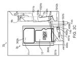
- FIG. 2C is a schematical illustration of an embodiment, where a tray is in an ejected open position and where an opening tool is inserted inside the apparatus.
- FIG. 3A is a schematical example illustration of another embodiment, where a handle is in a shortened closed position and where an opening tool is inserted inside the apparatus.
- FIG. 3B is a schematical example illustration of an embodiment, where a handle is in an extended open position and where an opening tool is inserted inside the apparatus.
- FIG. 4A is a schematical example illustration of another embodiment, where a tray is in a retracted closed position inside an apparatus.
- FIG. 4B is a schematical example illustration of an embodiment, where a tray is in a retracted closed position and where an opening tool is inserted inside the apparatus.
- FIG. 4C is a schematical example illustration of an embodiment, where a tray is in an ejected open position and where an opening tool is inserted inside the apparatus.
- FIG. 5A is a schematical example illustration of another embodiment, where a tray is in a retracted closed position inside an apparatus.
- FIG. 5B is a schematical example illustration of an embodiment, where a tray is in a retracted closed position and where an opening tool is inserted inside the apparatus.
- FIG. 5C is a schematical example illustration of an embodiment, where a tray is in an ejected open position and where an opening tool is inserted inside the apparatus.
- Mobile wireless devices such as mobile phones, laptops, tablets, smart watches and other smart wearables or cars with an on-board navigational system may need an integrated circuit card. It is also possible to use an external smart card reader for reading an integrated circuit card.
- an integrated circuit card or a smart card may be any of a Subscriber Identity Module card (SIM card), a memory card, an identity card or a card which is suitable for making purchases, etc.
- SIM card Subscriber Identity Module
- the cards may be of different sizes.
- the SIM card has been standardized and has four typical sizes according to the standards: full-size SIM 1st form factor (1FF), mini-SIM 2nd form-factor (2FF), micro-SIM 3rd form-factor (3FF), and nano-SIM 4th form-factor (4FF).
- memory card families have been standardized into various sizes which may be characterized as standard, mini, micro, nano etc. Some pieces of electronic equipment using the integrated circuit card may also accept more than one integrated circuit card.
- an abbreviated term “IC card” is used for an integrated circuit card which is intended to represent all types of integrated circuit cards of all sizes and varieties, including, but not limited to, SIM cards, memory cards, smart cards, payments cards, etc.
- the IC card is removed by a user. For this reason, it may be desirable to provide an apparatus for a user to safely remove and replace the IC card without the risk of corrupting the IC card, such as a SIM card.
- There is a risk of data corruption if the connection to the IC card is unexpectedly interrupted. This may happen when the user ejects, completely or partially, the IC card while the apparatus holding the IC card is still on and possibly reading the IC card.
- a switch may be used to give a warning to the program software before the user ejects the IC card. Further, another switch may be used to detect that the IC card is fully inserted. The warning may be used to shut down the apparatus. Further in some apparatuses, two separate devices may be used; one for giving the warning and another one for detecting that the IC card is fully inserted.
- FIG. 1A is a schematical illustration of an embodiment, where a tray 3 is in a retracted closed position inside an apparatus 1 a .
- FIG. 1A represents an initial stationary position of the tray 3 .
- the apparatus 1 a comprises a housing 2 and the tray 3 which is connected to the housing 2 in a movable manner.
- the tray 3 has a retracted closed position and an ejected open position with respect to the housing 2 .
- the apparatus comprises an ejector 4 configured to eject the tray 3 to the ejected open position.
- the ejector 4 may be a lever 401 or a similar type of device configured to push the tray 3 to the ejected open position.
- the tray 3 may carry for example two IC cards.
- the tray 3 may carry a SIM card 11 and additionally or alternatively a memory card 12 as illustrated in the example of the apparatus 1 a in FIG. 1A .
- the SIM card 11 and the memory card 12 are releasably attached to the tray 3 and to slots 303 , 304 .
- FIG. 1B is a schematical example illustration of an embodiment, where the tray 3 is in a retracted closed position and where an opening tool 6 is inserted inside the apparatus 1 a .
- the apparatus 1 a comprises a push member 5 configured to operate the ejector 4 to eject the tray 3 to the ejected open position when an external force Fe is applied to the push member 5 with the opening tool 6 .
- the push member 5 may be a rod or cylindrical shaped solid piece or a plate with a shaped portion for receiving the external force Fe and for closing the switch 7 .
- the push member 5 may be made out of metal or plastic.
- the shaped portion may be formed by bending, whereby the shaped portion is a bent portion 501 as illustrated in FIGS.
- the push member 5 has a first position and a second position, wherein the push member 5 is in the first position when the tray 3 is in the retracted closed position.
- the push member 5 is configured to receive the external force Fe for moving the push member 5 into the second position and to operate the ejector 4 to eject the tray 3 to the ejected open position when the push member 5 is moved to the second position.
- the push member 5 is further configured to stay in the second position and maintain the second position even when the external force Fe is removed.
- the tray 3 comprises a handle 301 comprising an opening 302 structured to receive the opening tool 6 for applying the external force Fe with the opening tool 6 to eject the tray 3 .
- the opening may be, for example, a through hole or similar type of structure for receiving the opening tool 6 .
- the opening tool 6 may be, for example, a pin or a bar or similar type of structure.
- the detection of insertion of the opening tool 6 which indicates that the tray 3 is about to be ejected, and the detection of the tray 3 being in the closed retracted position is enabled by a switch 7 .
- the switch 7 has a first electric position and a second electric position.
- the first electric position illustrated in FIG. 1B and indicated with an arrow 14 , is a closed position of the switch 7 .
- the second position illustrated in FIG. 1A is an open position of the switch 7 .
- the switch 7 is configured to receive the external force Fe and to switch to the first electric position in response to receiving the external force Fe, and the push member 5 is configured to maintain the switch 7 in the first electric position in response to the push member 5 being moved to the second position.
- the switch 7 comprises a first electric contact element 701 and a second electric contact element 702 .
- the opening tool 6 causes the first electric contact element 701 to close the switch 7 by moving the first electric contact element 701 into contact with the second electric contact element 702 .
- opening 302 may be arranged into the housing 2 (not illustrated in FIG. 1B ), whereby the handle may be structured narrower compared to the handle 301 illustrated in FIG. 1B .
- the electric contact elements 701 , 702 may be, for example, contact springs.
- the contact elements may be made out of metal and they may have a gold plating on the surface of the metal.
- the push member 5 may be made out of a metal plate or a plastic plate, whereby the push member 5 is a push plate.
- the first electric contact element 701 is fixed from a first end 7011 and a second end 7012 , for example, to soldered joints.
- the second electric contact element 702 is fixed from an end 7021 , for example, to a solder joint.
- the first electric contact element 701 functions as a spring which is able to bend and return back to its initial position.
- the second electric contact element 702 may function as a spring.
- a second bent portion 7014 moves in contact with the second electric contact element 702 when the first electric contact element 701 is pushed by the opening tool 6 from the first bent portion 7013 .
- the second electric contact element 702 moves when it is pushed by the first electric contact element 701 .
- a contact point between the opening tool 6 and the first bent portion 7013 is indicated inside a circle 15 .
- the movement of the first bent portion 7013 is indicated with the arrow 14 .
- the switch 7 when connected, closes an electric circuit 8 of a circuit board 9 , enabling a first signal S 1 indicating, that the tray 3 is about to be ejected.
- the first signal S 1 may be a power off signal transmitted to a control unit 10 or a software module, such as a computer, which safely switches off the apparatus 1 a.
- FIG. 1C is a schematical example illustration of an embodiment, where the tray 3 is in an ejected open position and where the opening tool 6 is inserted inside the apparatus 1 a .
- the opening tool 6 is inserted to its extreme position inside the apparatus 1 a .
- the ejector 4 may comprise a lever 401 comprising at least one pivotal connection 402 enabling the pivoting of the lever 401 .
- the pivoting of the lever 401 causes the moving of the tray 3 to the ejected open position when the lever 401 is pivoted around the pivotal connection 402 in response to an external force Fe applied to the push member 5 with the opening tool 6 .
- the pivotal connection 402 may be, in some embodiments, a hole around a shaft, which may function as a bearing.
- the shaft may be connected to the housing 2 .
- the bent portion 501 of the push member 5 pushes a third bent portion 7015 of the first electric contact element 701 keeping the switch 7 closed. This contact point is indicated inside a circle 15 a .
- the push member 5 is configured to maintain the switch 7 closed when the tray 3 is fully ejected to the open position.
- FIG. 1D is a schematical example illustration of an embodiment, where the tray 3 is in an ejected open position and where the opening tool 6 is removed from the apparatus 1 a .
- the push member 5 is configured to maintain the switch 7 closed when the tray 3 is fully ejected to the open position even after the opening tool 6 is removed by the user.
- the switch 7 is continuously connected.
- the apparatus may be configured such that the switching of the switch 7 is opposite to what is disclosed in embodiments illustrated in FIGS. 1A to 1D .
- the switching of the switch 7 may be configured in such a way that firstly the switch is opened when the external force Fe of the opening tool 6 is applied to the switch 7 and secondly the switch 7 is closed when the tray 3 is returned back to the retracted closed position (not illustrated in FIGS. 1A to 1D ).
- FIG. 1E is a schematical example illustration of an embodiment, where the tray 3 is returned back in a retracted closed position and where the opening tool 6 is removed from the apparatus 1 a .
- the embodiment illustrated in FIG. 1E is similar to the embodiment illustrated in FIG. 1A with the exception that a second signal S 2 is enabled, indicating that the tray 3 is back in the retracted closed position.
- the tray 3 is returned back to the retracted closed position by the user pushing the handle 301 of the tray 3 .
- the push member 5 is configured to open the switch 7 by causing the first electric contact element 701 to disconnect contact with the second electric contact element 702 when the tray 3 is returned back to the retracted closed position.
- the first electric contact element 701 moves to its initial position and disconnects the switch 7 .
- the switch 7 when disconnected, enables a second signal S 2 which may comprise a software wake-up signal.
- the second signal S 2 may be transmitted to a control unit 10 after the first signal S 1 has ceased.
- the second signal S 2 indicates that the tray 3 is fully inserted and the power of the apparatus may be safely turned back on. In some embodiment the second signal S 2 is transmitted to the software of the control unit 10 .
- FIG. 2A is a schematical example illustration of an embodiment, where a tray 3 b is in a retracted closed position.
- FIG. 2B is a schematical example illustration of the apparatus 1 b where the tray 3 b is in a retracted closed position and where the opening tool 6 is inserted inside the apparatus 1 b .
- the apparatus 1 b illustrated in FIGS. 2A and 2B is similar to the apparatus 1 a illustrated in FIGS. 1A and 1B with the exception that an ejector 4 b is different and it is located in a different place in the apparatus 1 b . Another exception is that no push member is utilized in the structure of the apparatus 1 b .
- the switch 7 b is disconnected in FIG. 2A . Similar to the embodiment illustrated in FIG.
- the opening tool 6 causes the closing of the switch 7 b .
- the ejector 4 b is in connection with a handle 301 b .
- the ejector 4 b is configured to push the handle 301 b when the tray 3 b is ejected.
- the ejector 4 b in some embodiments, may be a lever 401 b , is located near the handle 301 b .
- the lever 401 may comprise a rotation stopper 407 b which limits the rotation of the lever 401 b to a predetermined position.
- FIG. 2C is a schematical illustration of an embodiment, where the tray 3 b is in an ejected open position and where the opening tool 6 is inserted inside the apparatus 1 b .
- the apparatus 1 b illustrated in FIG. 2C is similar to the embodiment illustrated in FIG. 1C with the exception that an extension 405 b of the lever 401 b maintains the switch 7 b closed.
- the switch 7 b is closed by the ejector 4 b even after the opening tool 6 is removed.
- the rotation of the lever 401 b is illustrated with an arrow 14 b .
- the rotation stopper 407 b limits the lever 401 b from being rotated too far away from the first electric contact element 701 b .
- the lever 401 b is returned back to the initial position illustrated with a dashed line after the user removes the opening tool 6 and after the user has pushed the tray 3 b back to the retracted closed position.
- the ejector 5 b is configured to maintain the switch 7 b in the first electric position when the ejector 5 b is moved from the first position to the second position.
- the ejector 5 b is moved back to the first position which causes the switch 7 b to switch from the first electric position to the second electric position.
- the ejector 4 b is configured to open the switch 7 b by causing the first electric contact element 701 b to disconnect the contact with the second electric contact element 702 b when the tray 3 b is returned back to the retracted closed position.
- the switch 7 b is opened when the extension 405 b is no longer pushing the first electric contact element 701 b.
- FIG. 3A is a schematical example illustration of an embodiment, where a handle 18 c is in a shortened closed position and where the opening tool 6 is inserted inside the apparatus 1 c .
- the embodiment illustrated in FIG. 3A is similar to the embodiment illustrated in FIG. 1B with the exception that no housing is utilized and the ejector 4 c is configured to move only the handle 18 c , while the tray 3 c is kept in an unmoved position inside the apparatus 1 c .
- the tray 3 c is configured to carry three IC cards.
- the first electric contact element 701 c is moved by the opening tool 6 causing an indication of imminent ejection of the tray. This event is indicated with the circle 15 .
- the handle 18 c comprises an opening 185 c for inserting the opening tool 6 inside the apparatus 1 c.
- FIG. 3B is a schematical example illustration of an embodiment, where the handle 18 c is in an extended open position and where the opening tool 6 is inserted inside the apparatus 1 c .
- the handle 18 c has been connected to the tray 3 c in a slidable manner.
- the handle 18 c may comprise telescopic members 181 c , 183 c which may be structured inside guide rails 182 c , 184 c of the tray 3 c .
- the handle 3 c may be moved in relation to the tray 3 c by sliding the telescopic members 181 c , 183 c inside the guide rails 182 c , 184 c .
- the switch 7 c is configured to receive an external force Fec and to switch to the first electric position in response to receiving the external force Fec, and the push member 5 c is configured to maintain the switch 5 c in the first electric position when the handle 18 c is ejected to the extended open position.
- the push member 5 c is moved back to the first position causing the switch 7 c to switch from the first electric position to the second electric position.
- the ejector 4 c which may be a lever 401 c , has pushed the handle 18 c away from the tray 3 c to the extended open position.
- the handle 18 c is moved when the lever 401 c pushes the first telescopic part 181 c with a first portion 403 c of the lever 401 c .
- the movement of the lever 401 c causes the sliding of the handle 4 c to the extended open position when the lever 401 c is pivoted around the pivotal connection 402 c .
- the opening tool 6 pushes a push member 5 c which operates the ejector 4 c .
- the handle 18 c When the handle 18 c is ejected to the extended open position and the push member 5 c is in its possible extreme position, the first electric contact element 701 c is kept in contact with the second electric contact element 702 c by the push member 5 c , which is indicated with the circle 15 a .
- the push member 5 c When the handle 18 c is pushed back to a shortened closed position by the user, also the push member 5 c is pushed back to its initial position, whereby the push member 5 c opens the switch 7 c by causing the first electric contact element 701 c to disconnect the contact with the second electric contact element 702 c .
- the shortened closed position is illustrated with dashed lines in FIG. 3B .
- FIG. 4A is a schematical example illustration of an embodiment, where a tray 3 d is in a retracted closed position inside the apparatus 1 d .
- FIG. 4B is a schematical example illustration of an embodiment, where the tray 3 d is in a retracted closed position and where the opening tool 6 is inserted inside the apparatus 1 d .
- FIG. 4C is a schematical example illustration of an embodiment, where the tray 3 d is in an ejected open position and where the opening tool 6 is inserted inside the apparatus 1 d .
- the mechanism of the embodiments illustrated in FIG. 4A , FIG. 4B and FIG. 4C is similar to that of the embodiments illustrated in FIG. 1A , FIG. 1B , and FIG.
- the tray 3 d comprises a plate 409 d between the ejector 4 d and the tray 3 d and at least one spring 408 d between the plate 409 d and the tray 3 d .
- the switch 7 d When the gap G is closed, the switch 7 d is closed by the aid of the push member 5 d pushing the first electric contact element 701 d into contact with the second electric contact element 702 c . At this point, the tray 3 d is not yet moved.
- the connection point between the push member 5 d and the first electric contact element 701 d is illustrated inside the circle 15 . Similar to the mechanism of embodiments illustrated in FIG. 1C , the switch 7 d is kept closed by the push member 5 d when the tray 3 d is fully ejected.
- the connection point between the push member 5 d and the first electric contact element 701 d is illustrated inside the circle 15 a .
- the push member 5 d opens the switch 7 d by causing the first electric contact element 701 d to disconnect the contact with the second electric contact element 702 d , when the tray 3 d is returned back to the retracted closed position.
- FIG. 5A is a schematical example illustration of an embodiment, where a tray 3 e is in a retracted closed position inside an apparatus 1 e .
- FIG. 5B is a schematical example illustration of an embodiment, where the tray 3 e is in a retracted closed position and where the opening tool 6 is inserted inside the apparatus 1 e .
- FIG. 5C is a schematical example illustration of an embodiment, where the tray 3 e is in an ejected open position and where the opening tool 6 is inserted inside the apparatus 1 e .
- the embodiments illustrated in FIG. 5A , FIG. 5B and FIG. 5C are similar to embodiments illustrated in FIG. 4A FIG. 4B , with the exception that the gap is implemented differently.
- the housing 2 e comprises a flap 19 e which functions as a spring moving the ejector 4 e away from the tray 3 e .
- a gap G 2 is thereby formed between the ejector 4 e and the tray 3 e .
- the operation in embodiments illustrated in FIGS. 5B and 5C is similar to the ones illustrated in FIGS. 4B and 4C and are not thereby explained further.
- the tray 3 , 3 b , 3 c , 3 d , 3 e or the handle 18 c of the apparatus 1 a , 1 b , 1 c , 1 d , 1 e may be ejected with an opening tool 6 by means of the ejector 4 , 4 b , 4 c , 4 d , 4 e and may be pushed back by the user, and the apparatus 1 a , 1 b , 1 c , 1 d , 1 e comprises only one switch 7 , 7 b , 7 c , 7 d , 7 e which firstly detects that the tray 3 , 3 b , 3 c , 3 d , 3 e or the handle 18 c is about to be ejected and secondly detects that the tray 3 , 3 b , 3 c , 3 d , 3 e or the handle 18 c is closed to the closed position.
- the tray 3 , 3 b , 3 c , 3 d , 3 e may be removed from the apparatus 1 a , 1 b , 1 c , 1 d , 1 e , without the risk of corrupting the IC card. Even if the user ejects the IC card when the apparatus 1 a , 1 b , 1 c , 1 d , 1 e is powered, the ejection of the IC card may be done safely.
- the apparatus 1 a , 1 b , 1 c , 1 d , 1 e has a simple structure.
- the functionality of the switch 7 , 7 b , 7 c , 7 d , 7 e may be accomplished by using only one structure and not two or more separate devices.
- space may be limited.
- the electronic equipment may be constructed smaller. The reducing of components inside the electronic equipment is useful and may results in savings from an economical point of view.
- the apparatus 1 a , 1 b , 1 c , 1 d , 1 e disclosed in the embodiments above is useful in a solution where the apparatus 1 a , 1 b , 1 c , 1 d , 1 e is used as a card tray module for an electronic communication device, such as a smart phone or a tablet or a smart wearable.
- the apparatus 1 a , 1 b , 1 c , 1 d , 1 e is particularly useful when the electronic communication device utilizes at least two IC cards.
- the IC card may be a subscriber identity module card (SIM card), a full-size SIM 1st form factor (IFF) card, a mini-SIM 2nd form factor (2FF) card, a micro-SIM 3rd form-factor (3FF) card, a nano-SIM 4th form-factor (4FF) card, a secure digital card (SD card), a mini secure digital card (miniSD card), a micro secure digital card (microSD card), a memory card, a storage card, and an expanded external memory card.
- SIM card subscriber identity module card
- IFF SIM 1st form factor
- 2FF mini-SIM 2nd form factor
- 3FF micro-SIM 3rd form-factor
- 4FF nano-SIM 4th form-factor
- FIGS. 1A-5C describe the apparatus 1 a , 1 b , 1 c , 1 d , 1 e disclosed with the opening 302 , 302 b , 185 c , 302 d , 302 e structured in the handle 301 , 301 b , 18 c , 301 d , 301 e
- the opening 302 , 302 b , 185 c , 302 d , 302 e may be, in some embodiments, structured in the housing 2 , 2 b , 2 c , 2 d , 2 e , for example in a cover of the housing 2 , 2 b , 2 c , 2 d , 2 e or in a separate cover outside the housing 2 , 2 b , 2 c , 2 d 2 e (not illustrated in FIGS. 1A-5C ).
- An embodiment of an apparatus comprises a housing; a tray connected to the housing in a movable manner, the tray having a retracted closed position and an ejected open position with respect to the housing; an ejector configured to eject the tray to the ejected open position; a push member having a first position and a second position, wherein the push member is in the first position when the tray is in the retracted closed position, the push member is configured to receive an external force for moving the push member into the second position and to operate the ejector to eject the tray to the ejected open position in response to the push member being moved to the second position, and the push member is further configured to stay in the second position and maintain the second position even when the external force is removed; and a switch comprising a first electric position and a second electric position; wherein the switch is configured to receive the external force and to switch to the first electric position in response to receiving the external force, and the push member is configured to maintain the switch in the first electric position in response to the push member being
- An embodiment of an apparatus comprises a housing; a tray connected to the housing in a movable manner, the tray having a retracted closed position and an ejected open position with respect to the housing; an ejector configured to eject the tray to the ejected open position; a push member configured to operate the ejector to eject the tray to the ejected open position when an external force is applied to the push member with an opening tool; a switch comprising a first electric contact element and a second electric contact element; wherein the electric contact element is configured to be caused to move by the opening tool to close the switch by causing the first electric contact element to come in contact with the second electric contact element when the external force is applied to the first electric contact element with the opening tool and before the external force is applied to the push member, and the push member is configured to maintain the switch closed when the tray is ejected to the open position; and wherein, when the tray is returned back to the retracted closed position, the push member is caused to open the switch by causing the first electric
- the ejector comprises a lever comprising at least one pivotal connection enabling the pivoting of the lever, causing the moving of the tray to the ejected open position when the lever is pivoted around the at least one pivotal connection in response to the external force applied to the push member with an opening tool.
- the push member is configured to operate the ejector to eject the tray to the ejected open position when the external force is applied to the push member with an opening tool.
- the switch comprises a first electric contact element and a second electric contact element.
- the first electric contact element is configured to be caused to move by the opening tool to close the switch by causing the first electric contact element to come in contact with the second electric contact element when the external force is applied to the first electric contact element with an opening tool and before the external force is applied to the push member.
- the push member has been moved back to the first position causing the switch to switch back from the first electric position to the second electric position and further causing the first electric contact element to disconnect the contact with the second electric contact element.
- the switch when connected, is configured to close an electric circuit of a circuit board, enabling a first signal informing that the tray is about to be ejected.
- the switch when disconnected, enables a second signal informing that the tray is back in the retracted closed position.
- the first signal comprises a power off signal.
- the switch when disconnected, enables a second signal comprising a software wake-up signal being transmitted to a control unit after the first signal has ceased.
- the tray comprises a handle comprising an opening structured to receive an opening tool for applying the external force with the opening tool to eject the tray.
- At least one of the first electric contact element and the second electric contact element is structured to function as a spring which is configured to move when pressed by the external force.
- the first electric contact element comprises a first contact spring and the second electric contact element comprises a second contact spring.
- At least one of the first electric contact element and the second electric contact element is made out of metal comprising a gold plating.
- the push member comprises a push plate.
- the tray is structured to releasably receive at least one of an integrated circuit card, a subscriber identity module card, a secure digital card, a memory card, a storage card, and an expanded external memory card.
- an electronic device comprises the apparatus.
- the apparatus further comprises an electronic device, the electronic device comprising the tray, the ejector, the push member, and the switch.
- An embodiment of an apparatus comprises a housing; a tray connected to the housing in a movable manner, the tray having a retracted closed position and an ejected open position with respect to the housing; an ejector configured to eject the tray to the ejected open position and having a first position and a second position, wherein the ejector is in the first position when the tray is in the retracted closed position, the ejector is configured to receive an external force for moving the ejector into the second position and for moving the tray into the ejected open position and is further configured to stay in the second position and maintain the second position even when the external force is removed; and a switch comprising a first electric position and a second electric position; wherein the switch is configured to receive the external force and to switch to the first electric position in response to receiving the external force, and the ejector is configured to maintain the switch in the first electric position in response to the ejector being moved to the second position; and wherein, in response to the tray being returned back to
- An embodiment of an apparatus comprises a housing; a tray connected to the housing in a movable manner, the tray having a retracted closed position and an ejected open position with respect to the housing; an ejector configured to eject the tray to the ejected open position when an external force is applied to the ejector with an opening tool; a switch comprising a first electric contact element and a second electric contact element; wherein the first electric contact element is configured to be caused to move by the opening tool to close the switch by causing the first electric contact element to come in contact with the second electric contact element when the external force is applied to the first electric contact element with the opening tool and before the external force is applied to the ejector, and the ejector is configured to maintain the switch closed when the tray is ejected to the open position; and wherein, when the tray is returned back to the retracted closed position, the ejector is caused to open the switch by causing the first electric contact element to disconnect the contact with the second electric contact element when the tray is returned back
- the ejector is configured to eject the tray to the ejected open position when an external force is applied to the ejector with an opening tool.
- the switch comprises a first electric contact element and a second electric contact element; wherein at the first electric position the first electric contact element is configured to be caused to move by the opening tool to close the switch by causing the first electric contact element to come in contact with the second electric contact element when the external force is applied to the first electric contact element with the opening tool and before the external force is applied to the ejector; and wherein, at the second electric position the ejector has been returned back to the first position causing the switch to switch back from the first electric position to the second electric position and further causing the first electric contact element to disconnect the contact with the second electric contact element.
- the apparatus comprises a handle, wherein the ejector is configured to push the handle when the tray is ejected.
- An embodiment of an apparatus comprises: a tray; a handle connected to the tray in a slidable manner, the handle having a shortened closed position and an extended open position with respect to the tray; an ejector configured to eject the handle to the extended open position; a push member configured to push the ejector to eject the handle to the extended open position and having a first position and a second position, wherein the push member is in the first position when the handle is in the shortened closed position, the push member is configured to receive an external force for moving the push member into the second position and to operate the ejector to eject the handle to the extended open position and is further configured to stay in the second position and maintain the second position even when the external force is removed; a switch comprising a first electric position and a second electric position; wherein the switch is configured to receive the external force and to switch to the first electric position in response to receiving the external force, and the push member is configured to maintain the switch in the first electric position in response to the handle being ejected to the extended
- An embodiment of an apparatus comprises a tray; a handle connected to the tray in a slidable manner and having a shortened closed position and an extended open position with respect to the tray; an ejector configured to eject the handle to the extended open position; a push member configured to push the ejector to eject the handle to the extended open position when an external force is applied to the push member with an opening tool; a switch comprising a first electric contact element and a second electric contact element; wherein the first electric contact element is configured to be caused to move by the opening tool to close the switch by causing the first electric contact element to come in contact with the second electric contact element when the external force is applied to the first electric contact element with the opening tool and before the external force is applied to the push member, and the push member is configured to maintain the switch closed when the handle is ejected to the open position; and wherein, when the handle is returned back to the shortened closed position, the push member is caused to open the switch by causing the first electric contact element to disconnect the contact with the second electric contact
- the switch comprises a first electric contact element and a second electric contact element; wherein at the first electric position the electric contact element is configured to be caused to move by the opening tool to close the switch by causing the first electric contact element to come in contact with the second electric contact element when the external force is applied to the first electric contact element and before the external force is applied to the ejector; and wherein, at the second electric position the push member has been returned back to the first position causing the switch to switch back from the first electric position to the second electric position and further causing the first electric contact element to disconnect the contact with the second electric contact element.
- the ejector comprises at least one lever, wherein the at least one lever comprises at least one pivotal connection enabling pivoting of the at least one lever, causing the sliding of the handle to the extended open position when the at least one lever is pivoted around the pivotal connection.
- the handle comprises an opening structured to receive an opening tool for applying the external force with the opening tool to eject the handle.
- An embodiment of an apparatus comprises a housing; a tray connected to the housing in a movable manner, the tray having a retracted closed position and an ejected open position with respect to the housing; an ejector configured to eject the tray to the ejected open position; a push member having a first position and a second position, wherein the push member is in the first position when the tray is in the retracted closed position, the push member is configured to receive an external force for moving the push member into the second position and to operate the ejector to eject the tray to the ejected open position in response to the push member being moved to the second position, and the push member is further configured to stay in the second position and maintain the second position even when the external force is removed; and a switch comprising a first electric position and a second electric position; wherein the switch is configured to receive the external force and to switch to the first electric position in response to the push member being applied by the external force and before the tray is being moved to the ejected open position; and where
- An embodiment of an apparatus comprises a housing; a tray connected to the housing in a movable manner, the tray having a retracted closed position and an ejected open position with respect to the housing; an ejector configured to eject the tray to the ejected open position; a push member configured to operate the ejector to eject the tray to the ejected open position when an external force is applied to the push member with an opening tool; a switch comprising a first electric contact element and a second electric contact element; wherein the first electric contact element is configured to be caused to move by the push member to close the switch by causing the first electric contact element to come in contact with the second electric contact element before the tray is ejected to the open position, and the push member is configured to maintain the switch closed when the tray is ejected to the open position; and wherein, when the tray is returned back to the retracted closed position, the push member is caused to open the switch by causing the first electric contact element to disconnect the contact with the second electric contact element when the
Landscapes
- Engineering & Computer Science (AREA)
- Physics & Mathematics (AREA)
- General Physics & Mathematics (AREA)
- Theoretical Computer Science (AREA)
- Artificial Intelligence (AREA)
- Computer Vision & Pattern Recognition (AREA)
- Coupling Device And Connection With Printed Circuit (AREA)
- Details Of Connecting Devices For Male And Female Coupling (AREA)
Priority Applications (5)
| Application Number | Priority Date | Filing Date | Title |
|---|---|---|---|
| US14/750,028 US9837765B2 (en) | 2015-06-25 | 2015-06-25 | Apparatus for ejecting at least one integrated circuit card |
| PCT/US2016/037308 WO2016209657A1 (fr) | 2015-06-25 | 2016-06-14 | Appareil d'éjection d'au moins une carte à circuit intégré |
| EP16735757.3A EP3314535B1 (fr) | 2015-06-25 | 2016-06-14 | Appareil pour ejecter une carte a puce |
| CN201680037214.3A CN107835996B (zh) | 2015-06-25 | 2016-06-14 | 用于弹出至少一个集成电路卡的装置 |
| US15/730,672 US10340634B2 (en) | 2015-06-25 | 2017-10-11 | Apparatus for ejecting at least one integrated circuit card |
Applications Claiming Priority (1)
| Application Number | Priority Date | Filing Date | Title |
|---|---|---|---|
| US14/750,028 US9837765B2 (en) | 2015-06-25 | 2015-06-25 | Apparatus for ejecting at least one integrated circuit card |
Related Child Applications (1)
| Application Number | Title | Priority Date | Filing Date |
|---|---|---|---|
| US15/730,672 Continuation US10340634B2 (en) | 2015-06-25 | 2017-10-11 | Apparatus for ejecting at least one integrated circuit card |
Publications (2)
| Publication Number | Publication Date |
|---|---|
| US20160380385A1 US20160380385A1 (en) | 2016-12-29 |
| US9837765B2 true US9837765B2 (en) | 2017-12-05 |
Family
ID=56360481
Family Applications (2)
| Application Number | Title | Priority Date | Filing Date |
|---|---|---|---|
| US14/750,028 Expired - Fee Related US9837765B2 (en) | 2015-06-25 | 2015-06-25 | Apparatus for ejecting at least one integrated circuit card |
| US15/730,672 Active US10340634B2 (en) | 2015-06-25 | 2017-10-11 | Apparatus for ejecting at least one integrated circuit card |
Family Applications After (1)
| Application Number | Title | Priority Date | Filing Date |
|---|---|---|---|
| US15/730,672 Active US10340634B2 (en) | 2015-06-25 | 2017-10-11 | Apparatus for ejecting at least one integrated circuit card |
Country Status (4)
| Country | Link |
|---|---|
| US (2) | US9837765B2 (fr) |
| EP (1) | EP3314535B1 (fr) |
| CN (1) | CN107835996B (fr) |
| WO (1) | WO2016209657A1 (fr) |
Cited By (3)
| Publication number | Priority date | Publication date | Assignee | Title |
|---|---|---|---|---|
| US10793342B2 (en) * | 2012-07-16 | 2020-10-06 | John Minson | Credit card dispenser |
| US11337326B2 (en) * | 2017-03-02 | 2022-05-17 | Samsung Electronics Co., Ltd. | Electronic device with a switch to prevent over-discharging of device battery |
| US11343929B2 (en) | 2019-09-03 | 2022-05-24 | Samsung Electronics Co., Ltd. | Method for controlling power using socket and electronic device supporting the same |
Families Citing this family (7)
| Publication number | Priority date | Publication date | Assignee | Title |
|---|---|---|---|---|
| KR102359957B1 (ko) * | 2015-06-02 | 2022-02-09 | 삼성전자주식회사 | 전자 장치 |
| CN107317897A (zh) * | 2017-07-05 | 2017-11-03 | 宇龙计算机通信科技(深圳)有限公司 | 终端卡座及终端 |
| US10881027B2 (en) * | 2018-10-21 | 2020-12-29 | Western Digital Technologies, Inc. | Sockets for removable data storage devices |
| CN109274389B (zh) * | 2018-10-22 | 2020-06-30 | 维沃移动通信有限公司 | 电子设备 |
| CN110189953B (zh) * | 2019-05-30 | 2021-08-17 | 维沃移动通信有限公司 | 移动终端、其控制方法及控制装置、计算机可读存储介质 |
| CN112306165B (zh) * | 2019-08-02 | 2023-09-08 | 戴尔产品有限公司 | 卡/机箱联接系统 |
| DE102024003418A1 (de) | 2024-10-17 | 2025-11-20 | Mercedes-Benz Group AG | Fernbedienung, insbesondere zum Ver- und Entriegeln oder Inbetriebnahme eines Kraftfahrzeuges |
Citations (23)
| Publication number | Priority date | Publication date | Assignee | Title |
|---|---|---|---|---|
| DE3916783A1 (de) | 1988-10-19 | 1990-04-26 | Landis & Gyr Ag | Vorrichtung zum lesen und/oder beschreiben von chip-karten |
| US6039587A (en) | 1997-09-19 | 2000-03-21 | Alps Electric Co., Ltd. | IC card connector device |
| US6577507B2 (en) * | 2001-10-16 | 2003-06-10 | Oki Electric Industry Co., Ltd. | Automatic circuit board plug-in system |
| US20040009690A1 (en) * | 2002-07-11 | 2004-01-15 | Japan Aviation Electronics Industry, Limited | Card slot assembly with electrically-controllable ejection mechanism |
| US20040140359A1 (en) | 2002-05-14 | 2004-07-22 | I/O Interconnect Inc. | Method and apparatus for safe data reading and writing to a memory card reader device |
| US6843670B2 (en) | 2000-06-29 | 2005-01-18 | Molex Incorporated | IC card connector |
| US20060226223A1 (en) | 2005-04-06 | 2006-10-12 | Northstar Systems Corp. | Socket of card reader (ii) for memory card with connecting terminals following specification of USB containing card-unloading structure |
| US7207814B2 (en) | 2005-06-17 | 2007-04-24 | Hon Hai Precision Ind. Co., Ltd. | Electrical card connector |
| US7258278B2 (en) * | 2005-06-01 | 2007-08-21 | Nokia Corporation | Electronic module reader |
| US7510415B2 (en) | 2007-07-02 | 2009-03-31 | Hon Hai Precision Ind. Co., Ltd. | Electrical card connector having ejecting mechanism |
| US20090149047A1 (en) * | 2007-12-06 | 2009-06-11 | Hon Hai Precision Ind. Co., Ltd. | Memory card connector with improved switch contacts for stably detection of card insertion or removal |
| US20100159724A1 (en) | 2006-06-05 | 2010-06-24 | Ayako Ida | Card connector with double cam |
| US7766678B1 (en) | 2008-11-10 | 2010-08-03 | Yamaichi Electronics Usa, Inc. | SIM card connector with eject mechanism |
| CN101944670A (zh) | 2010-08-27 | 2011-01-12 | 华为终端有限公司 | 一种智能卡插座、移动终端和移动终端的工作方法 |
| US20110136360A1 (en) | 2009-12-03 | 2011-06-09 | Hon Hai Precision Industry Co., Ltd. | Electrical card connector |
| US8337223B2 (en) | 2010-09-30 | 2012-12-25 | Apple Inc. | Mini-sim connector |
| US20140049920A1 (en) | 2010-04-19 | 2014-02-20 | Apple Inc. | Compact ejectable component assemblies in electronic devices |
| US20140101466A1 (en) | 2011-05-17 | 2014-04-10 | Sony Corporation | Information processing device and method, record medium and program |
| US8777669B2 (en) | 2011-04-29 | 2014-07-15 | Hon Hai Precision Industry Co., Ltd. | Tray-type card connector with dual feelings during both insertion and ejection of tray |
| US20140273564A1 (en) | 2013-03-12 | 2014-09-18 | Molex Incorporated | Card connector |
| US20140315404A1 (en) * | 2013-01-18 | 2014-10-23 | Molex Incorporated | Low profile connector |
| US20150018041A1 (en) | 2012-03-28 | 2015-01-15 | Yota Devices Ipr Ltd. | Display device including a display and a hardware power button |
| US20150022981A1 (en) | 2013-07-18 | 2015-01-22 | Molex Incorporated | Electronic card connection device and electronic device |
Family Cites Families (3)
| Publication number | Priority date | Publication date | Assignee | Title |
|---|---|---|---|---|
| CN2800545Y (zh) * | 2005-04-19 | 2006-07-26 | 富士康(昆山)电脑接插件有限公司 | 电子卡连接器 |
| US8680131B2 (en) * | 2012-07-25 | 2014-03-25 | Jenrin Discovery, Inc. | Cannabinoid receptor antagonists/inverse agonists useful for treating disease conditions, including metabolic disorders and cancers |
| CN203071322U (zh) * | 2013-01-18 | 2013-07-17 | 莫仕连接器(成都)有限公司 | 电连接器 |
-
2015
- 2015-06-25 US US14/750,028 patent/US9837765B2/en not_active Expired - Fee Related
-
2016
- 2016-06-14 EP EP16735757.3A patent/EP3314535B1/fr active Active
- 2016-06-14 CN CN201680037214.3A patent/CN107835996B/zh active Active
- 2016-06-14 WO PCT/US2016/037308 patent/WO2016209657A1/fr not_active Ceased
-
2017
- 2017-10-11 US US15/730,672 patent/US10340634B2/en active Active
Patent Citations (23)
| Publication number | Priority date | Publication date | Assignee | Title |
|---|---|---|---|---|
| DE3916783A1 (de) | 1988-10-19 | 1990-04-26 | Landis & Gyr Ag | Vorrichtung zum lesen und/oder beschreiben von chip-karten |
| US6039587A (en) | 1997-09-19 | 2000-03-21 | Alps Electric Co., Ltd. | IC card connector device |
| US6843670B2 (en) | 2000-06-29 | 2005-01-18 | Molex Incorporated | IC card connector |
| US6577507B2 (en) * | 2001-10-16 | 2003-06-10 | Oki Electric Industry Co., Ltd. | Automatic circuit board plug-in system |
| US20040140359A1 (en) | 2002-05-14 | 2004-07-22 | I/O Interconnect Inc. | Method and apparatus for safe data reading and writing to a memory card reader device |
| US20040009690A1 (en) * | 2002-07-11 | 2004-01-15 | Japan Aviation Electronics Industry, Limited | Card slot assembly with electrically-controllable ejection mechanism |
| US20060226223A1 (en) | 2005-04-06 | 2006-10-12 | Northstar Systems Corp. | Socket of card reader (ii) for memory card with connecting terminals following specification of USB containing card-unloading structure |
| US7258278B2 (en) * | 2005-06-01 | 2007-08-21 | Nokia Corporation | Electronic module reader |
| US7207814B2 (en) | 2005-06-17 | 2007-04-24 | Hon Hai Precision Ind. Co., Ltd. | Electrical card connector |
| US20100159724A1 (en) | 2006-06-05 | 2010-06-24 | Ayako Ida | Card connector with double cam |
| US7510415B2 (en) | 2007-07-02 | 2009-03-31 | Hon Hai Precision Ind. Co., Ltd. | Electrical card connector having ejecting mechanism |
| US20090149047A1 (en) * | 2007-12-06 | 2009-06-11 | Hon Hai Precision Ind. Co., Ltd. | Memory card connector with improved switch contacts for stably detection of card insertion or removal |
| US7766678B1 (en) | 2008-11-10 | 2010-08-03 | Yamaichi Electronics Usa, Inc. | SIM card connector with eject mechanism |
| US20110136360A1 (en) | 2009-12-03 | 2011-06-09 | Hon Hai Precision Industry Co., Ltd. | Electrical card connector |
| US20140049920A1 (en) | 2010-04-19 | 2014-02-20 | Apple Inc. | Compact ejectable component assemblies in electronic devices |
| CN101944670A (zh) | 2010-08-27 | 2011-01-12 | 华为终端有限公司 | 一种智能卡插座、移动终端和移动终端的工作方法 |
| US8337223B2 (en) | 2010-09-30 | 2012-12-25 | Apple Inc. | Mini-sim connector |
| US8777669B2 (en) | 2011-04-29 | 2014-07-15 | Hon Hai Precision Industry Co., Ltd. | Tray-type card connector with dual feelings during both insertion and ejection of tray |
| US20140101466A1 (en) | 2011-05-17 | 2014-04-10 | Sony Corporation | Information processing device and method, record medium and program |
| US20150018041A1 (en) | 2012-03-28 | 2015-01-15 | Yota Devices Ipr Ltd. | Display device including a display and a hardware power button |
| US20140315404A1 (en) * | 2013-01-18 | 2014-10-23 | Molex Incorporated | Low profile connector |
| US20140273564A1 (en) | 2013-03-12 | 2014-09-18 | Molex Incorporated | Card connector |
| US20150022981A1 (en) | 2013-07-18 | 2015-01-22 | Molex Incorporated | Electronic card connection device and electronic device |
Non-Patent Citations (4)
| Title |
|---|
| "International Preliminary Report on Patentability Issued in PCT Application No. PCT/US2016/037308", dated Sep. 4, 2017, 8 Pages. |
| "Second Written Opinion Issued in PCT Application No. PCT/US2016/037308", dated May 17, 2017, 4 Pages. |
| International Search Report and Written Opinion Issued in PCT Application No. PCT/US2016/037308, dated Sep. 16, 2016, 14 Pages. |
| Purcher, Jack, "Apple Invents Secure Touchscreen SIM Card Tray Ejection System", Published on: Apr. 3, 2014 Available at: http://www.patentlyapple.com/patently-apple/2014/04/apple-invents-secure-touchscreen-sim-card-tray-ejection-system.html. |
Cited By (3)
| Publication number | Priority date | Publication date | Assignee | Title |
|---|---|---|---|---|
| US10793342B2 (en) * | 2012-07-16 | 2020-10-06 | John Minson | Credit card dispenser |
| US11337326B2 (en) * | 2017-03-02 | 2022-05-17 | Samsung Electronics Co., Ltd. | Electronic device with a switch to prevent over-discharging of device battery |
| US11343929B2 (en) | 2019-09-03 | 2022-05-24 | Samsung Electronics Co., Ltd. | Method for controlling power using socket and electronic device supporting the same |
Also Published As
| Publication number | Publication date |
|---|---|
| US10340634B2 (en) | 2019-07-02 |
| CN107835996A (zh) | 2018-03-23 |
| EP3314535B1 (fr) | 2021-07-21 |
| EP3314535A1 (fr) | 2018-05-02 |
| WO2016209657A1 (fr) | 2016-12-29 |
| CN107835996B (zh) | 2021-06-29 |
| US20180034208A1 (en) | 2018-02-01 |
| US20160380385A1 (en) | 2016-12-29 |
Similar Documents
| Publication | Publication Date | Title |
|---|---|---|
| US10340634B2 (en) | Apparatus for ejecting at least one integrated circuit card | |
| KR101040051B1 (ko) | 접촉들의 2가지 표준 세트들을 갖는 메모리 카드들 | |
| EP1847943A1 (fr) | Connecteur de carte | |
| US8460021B1 (en) | Card insert/eject mechanism having a position-limiting plate engaging a sliding block | |
| US10254806B2 (en) | Apparatus for receiving at least one integrated circuit card | |
| US7804683B2 (en) | Electronic device component eject mechanism | |
| CN107646097B (zh) | 用于移动载体的装置 | |
| TWM393075U (en) | Card connector | |
| CN111697399B (zh) | 用于移动通信终端的多卡插座及包括其的多卡连接器 | |
| EP3010210B1 (fr) | Structure de fente pour carte | |
| US7458857B2 (en) | Electronic device and card-receiving device thereof | |
| US8608072B2 (en) | Memory card socket and data processing device including the same | |
| JP4530318B2 (ja) | プラグイン型icカード用アダプタ | |
| EP2978195B1 (fr) | Terminal de communication compatible avec de multiples types de cartes intelligentes | |
| US8068344B2 (en) | Electronic apparatus | |
| US6921019B2 (en) | Memory card reader | |
| CN104051878B (zh) | 卡插件 | |
| CN105576442B (zh) | 卡槽结构 | |
| JP4570644B2 (ja) | カード用コネクタ | |
| JP2003007397A (ja) | カード脱着機構 | |
| US7690935B2 (en) | Connector structure | |
| US20180092232A1 (en) | Tray Operating System and Corresponding Methods | |
| CN203967289U (zh) | 卡片连接器 | |
| KR20200131087A (ko) | 휴대용 카드 리더기 |
Legal Events
| Date | Code | Title | Description |
|---|---|---|---|
| AS | Assignment |
Owner name: MICROSOFT TECHNOLOGY LICENSING, LLC, WASHINGTON Free format text: ASSIGNMENT OF ASSIGNORS INTEREST;ASSIGNOR:HEISKANEN, JUUSO;REEL/FRAME:035905/0955 Effective date: 20150623 |
|
| STCF | Information on status: patent grant |
Free format text: PATENTED CASE |
|
| MAFP | Maintenance fee payment |
Free format text: PAYMENT OF MAINTENANCE FEE, 4TH YEAR, LARGE ENTITY (ORIGINAL EVENT CODE: M1551); ENTITY STATUS OF PATENT OWNER: LARGE ENTITY Year of fee payment: 4 |
|
| FEPP | Fee payment procedure |
Free format text: MAINTENANCE FEE REMINDER MAILED (ORIGINAL EVENT CODE: REM.); ENTITY STATUS OF PATENT OWNER: LARGE ENTITY |
|
| LAPS | Lapse for failure to pay maintenance fees |
Free format text: PATENT EXPIRED FOR FAILURE TO PAY MAINTENANCE FEES (ORIGINAL EVENT CODE: EXP.); ENTITY STATUS OF PATENT OWNER: LARGE ENTITY |
|
| STCH | Information on status: patent discontinuation |
Free format text: PATENT EXPIRED DUE TO NONPAYMENT OF MAINTENANCE FEES UNDER 37 CFR 1.362 |
|
| FP | Lapsed due to failure to pay maintenance fee |
Effective date: 20251205 |