US9850635B2 - Irrigation network valve - Google Patents
Irrigation network valve Download PDFInfo
- Publication number
- US9850635B2 US9850635B2 US14/904,397 US201414904397A US9850635B2 US 9850635 B2 US9850635 B2 US 9850635B2 US 201414904397 A US201414904397 A US 201414904397A US 9850635 B2 US9850635 B2 US 9850635B2
- Authority
- US
- United States
- Prior art keywords
- gate
- valve
- stop valve
- float
- inlet
- Prior art date
- Legal status (The legal status is an assumption and is not a legal conclusion. Google has not performed a legal analysis and makes no representation as to the accuracy of the status listed.)
- Active, expires
Links
Images


Classifications
-
- E—FIXED CONSTRUCTIONS
- E02—HYDRAULIC ENGINEERING; FOUNDATIONS; SOIL SHIFTING
- E02B—HYDRAULIC ENGINEERING
- E02B13/00—Irrigation ditches, i.e. gravity flow, open channel water distribution systems
- E02B13/02—Closures for irrigation conduits
-
- F—MECHANICAL ENGINEERING; LIGHTING; HEATING; WEAPONS; BLASTING
- F16—ENGINEERING ELEMENTS AND UNITS; GENERAL MEASURES FOR PRODUCING AND MAINTAINING EFFECTIVE FUNCTIONING OF MACHINES OR INSTALLATIONS; THERMAL INSULATION IN GENERAL
- F16K—VALVES; TAPS; COCKS; ACTUATING-FLOATS; DEVICES FOR VENTING OR AERATING
- F16K31/00—Actuating devices; Operating means; Releasing devices
- F16K31/12—Actuating devices; Operating means; Releasing devices actuated by fluid
- F16K31/18—Actuating devices; Operating means; Releasing devices actuated by fluid actuated by a float
- F16K31/30—Actuating devices; Operating means; Releasing devices actuated by fluid actuated by a float actuating a gate valve or sliding valve
-
- F—MECHANICAL ENGINEERING; LIGHTING; HEATING; WEAPONS; BLASTING
- F16—ENGINEERING ELEMENTS AND UNITS; GENERAL MEASURES FOR PRODUCING AND MAINTAINING EFFECTIVE FUNCTIONING OF MACHINES OR INSTALLATIONS; THERMAL INSULATION IN GENERAL
- F16K—VALVES; TAPS; COCKS; ACTUATING-FLOATS; DEVICES FOR VENTING OR AERATING
- F16K31/00—Actuating devices; Operating means; Releasing devices
- F16K31/12—Actuating devices; Operating means; Releasing devices actuated by fluid
- F16K31/18—Actuating devices; Operating means; Releasing devices actuated by fluid actuated by a float
- F16K31/32—Actuating devices; Operating means; Releasing devices actuated by fluid actuated by a float actuating a tap or cock
-
- F—MECHANICAL ENGINEERING; LIGHTING; HEATING; WEAPONS; BLASTING
- F16—ENGINEERING ELEMENTS AND UNITS; GENERAL MEASURES FOR PRODUCING AND MAINTAINING EFFECTIVE FUNCTIONING OF MACHINES OR INSTALLATIONS; THERMAL INSULATION IN GENERAL
- F16K—VALVES; TAPS; COCKS; ACTUATING-FLOATS; DEVICES FOR VENTING OR AERATING
- F16K5/00—Plug valves; Taps or cocks comprising only cut-off apparatus having at least one of the sealing faces shaped as a more or less complete surface of a solid of revolution, the opening and closing movement being predominantly rotary
- F16K5/04—Plug valves; Taps or cocks comprising only cut-off apparatus having at least one of the sealing faces shaped as a more or less complete surface of a solid of revolution, the opening and closing movement being predominantly rotary with plugs having cylindrical surfaces; Packings therefor
- F16K5/0414—Plug channel at 90 degrees to the inlet
-
- F—MECHANICAL ENGINEERING; LIGHTING; HEATING; WEAPONS; BLASTING
- F16—ENGINEERING ELEMENTS AND UNITS; GENERAL MEASURES FOR PRODUCING AND MAINTAINING EFFECTIVE FUNCTIONING OF MACHINES OR INSTALLATIONS; THERMAL INSULATION IN GENERAL
- F16K—VALVES; TAPS; COCKS; ACTUATING-FLOATS; DEVICES FOR VENTING OR AERATING
- F16K5/00—Plug valves; Taps or cocks comprising only cut-off apparatus having at least one of the sealing faces shaped as a more or less complete surface of a solid of revolution, the opening and closing movement being predominantly rotary
- F16K5/04—Plug valves; Taps or cocks comprising only cut-off apparatus having at least one of the sealing faces shaped as a more or less complete surface of a solid of revolution, the opening and closing movement being predominantly rotary with plugs having cylindrical surfaces; Packings therefor
- F16K5/0442—Spindles and actuating means
-
- F—MECHANICAL ENGINEERING; LIGHTING; HEATING; WEAPONS; BLASTING
- F16—ENGINEERING ELEMENTS AND UNITS; GENERAL MEASURES FOR PRODUCING AND MAINTAINING EFFECTIVE FUNCTIONING OF MACHINES OR INSTALLATIONS; THERMAL INSULATION IN GENERAL
- F16K—VALVES; TAPS; COCKS; ACTUATING-FLOATS; DEVICES FOR VENTING OR AERATING
- F16K5/00—Plug valves; Taps or cocks comprising only cut-off apparatus having at least one of the sealing faces shaped as a more or less complete surface of a solid of revolution, the opening and closing movement being predominantly rotary
- F16K5/08—Details
- F16K5/12—Arrangements for modifying the way in which the rate of flow varies during the actuation of the valve
-
- E—FIXED CONSTRUCTIONS
- E02—HYDRAULIC ENGINEERING; FOUNDATIONS; SOIL SHIFTING
- E02B—HYDRAULIC ENGINEERING
- E02B2201/00—Devices, constructional details or methods of hydraulic engineering not otherwise provided for
- E02B2201/50—Devices for sequentially discharging constant liquid quantities, e.g. into different irrigation channels
-
- Y—GENERAL TAGGING OF NEW TECHNOLOGICAL DEVELOPMENTS; GENERAL TAGGING OF CROSS-SECTIONAL TECHNOLOGIES SPANNING OVER SEVERAL SECTIONS OF THE IPC; TECHNICAL SUBJECTS COVERED BY FORMER USPC CROSS-REFERENCE ART COLLECTIONS [XRACs] AND DIGESTS
- Y10—TECHNICAL SUBJECTS COVERED BY FORMER USPC
- Y10T—TECHNICAL SUBJECTS COVERED BY FORMER US CLASSIFICATION
- Y10T137/00—Fluid handling
- Y10T137/7287—Liquid level responsive or maintaining systems
- Y10T137/7358—By float controlled valve
- Y10T137/7365—Single float controls plural valves
-
- Y—GENERAL TAGGING OF NEW TECHNOLOGICAL DEVELOPMENTS; GENERAL TAGGING OF CROSS-SECTIONAL TECHNOLOGIES SPANNING OVER SEVERAL SECTIONS OF THE IPC; TECHNICAL SUBJECTS COVERED BY FORMER USPC CROSS-REFERENCE ART COLLECTIONS [XRACs] AND DIGESTS
- Y10—TECHNICAL SUBJECTS COVERED BY FORMER USPC
- Y10T—TECHNICAL SUBJECTS COVERED BY FORMER US CLASSIFICATION
- Y10T137/00—Fluid handling
- Y10T137/7287—Liquid level responsive or maintaining systems
- Y10T137/7358—By float controlled valve
- Y10T137/7404—Plural floats
-
- Y—GENERAL TAGGING OF NEW TECHNOLOGICAL DEVELOPMENTS; GENERAL TAGGING OF CROSS-SECTIONAL TECHNOLOGIES SPANNING OVER SEVERAL SECTIONS OF THE IPC; TECHNICAL SUBJECTS COVERED BY FORMER USPC CROSS-REFERENCE ART COLLECTIONS [XRACs] AND DIGESTS
- Y10—TECHNICAL SUBJECTS COVERED BY FORMER USPC
- Y10T—TECHNICAL SUBJECTS COVERED BY FORMER US CLASSIFICATION
- Y10T137/00—Fluid handling
- Y10T137/7287—Liquid level responsive or maintaining systems
- Y10T137/7358—By float controlled valve
- Y10T137/7439—Float arm operated valve
- Y10T137/7446—With flow guide or restrictor
Definitions
- This disclosure concerns flow control valves for immersion in channels of the type built for irrigation.
- Irrigators rely on channels for delivery of water to areas where crops are grown. Such areas may have a laser-levelled surface so that an inbuilt incline ensures the water runs to the end of the channel whenever water is available.
- float-operated valves that include a rise and fall stop gate capable of stopping flow in the pipe supplying an installation such as a LINDSAY® overhead irrigation device.
- U.S. Pat. No. 1,343,871 describes a system for supplying water to different parts of a field by a pipe that fills a group of containers, each with its own float valve to allow water to flow to subsidiary boxes.
- a ball float on the end of an arm that progressively closes a valve to a valve seat stopping the flow is out of sight inside the container.
- U.S. Pat. No. 2,362,747 describes a chain of tanks, each with an outlet for discharge into a soil channel.
- a control tank in the chain contains a float valve that opens and closes a valve in a pipe that supplies the whole chain.
- U.S. Pat. No. 6,953,156 describes a system for irrigating sloping land. This too relies on a ball-type float valve that controls water entry into a distributor tank from which branch pipes flow to different areas depending on their slope.
- the apparatus aspect of the disclosure provides a stop valve for a duct pipe feeding an irrigation channel comprising a duct with an inlet and an outlet, a rise and fall gate between the inlet and outlet, a pair of float arms supported on pivots lying on an axis transverse to the duct direction and a float for determining the inclination of each float arm.
- the duct may be linear with the gate at 90 degrees to the duct axis.
- the gate may have static guides that are wider than the inlet portion of the valve body and a flat gate that slides in the guides between an open position clear of the inlet portion and a closed position in which the gate lies in register with the inlet portion, thereby preventing flow.
- the float arms may be rods that are free to rotate about the pivots, attached at one end to the rise and fall gate plate and at the opposite end to the float.
- the float may be spaced from the end of an aim by a rigid link.
- the duct may have a semi-circumferential slot in its upper half through which the leading edge of the gate plate projects.
- the leading edge may be semi-circular in order to conform to the circumferential wall of the duct.
- the gate plate may be substantially M-shaped with the upright outer members sliding in the gap between the parallel edges of the gate guides.
- the inlet may have a ring flange for joining it to the ring flange of a pipe, which supplies the channel.
- channel overflow may be prevented with consequent crop saving.
- valve may not be watertight, leakage level is acceptable.
- the valve requires minimal maintenance and has reduced vulnerability to blockage.
- a second apparatus aspect of the disclosure provides a stop valve for a tank comprising a duct with an inlet and an outlet, a rise and fall gate between the inlet and outlet, a float arm supported by the duct operable to open and close the gate in response to rise and fall movement of the float.
- the duct may be T-shaped with the two outlets lying at 90 degrees to the inlet providing an axis parallel to the gate, whereby the float arm is pivotable about the axis, the gate being at one end of the arm and a float at the opposite end.
- the T-shaped body has a cylindrical outlet portion with pairs of circumferential slots lying mutually opposite, and a coaxial sleeve inside the outlet portion, which is rotatable, in order to support a pair of parallel float arms that extend through the sleeve and the circumferential slots in order to connect the gate to a pair of floats attached to the float arms.
- the circumferential gap between the valve sleeve and the valve body may be bridged by self-lubricating strip bearings.
- the gate may have static guides that are wider than the inlet portion of the valve body and a flat gate that slides in the guides between an open position clear of the inlet portion and a closed position in which the gate lies in register with the inlet portion, thereby preventing flow.
- the float arms may be rods fixed to the sleeve but free to rotate in the circumferential slots in order to cause the gate to execute linear motion moving from rise to fall and back.
- Each float arm may be connected to the gate by a link that accommodates the difference in linear and arcuate motion.
- the gate lies in an intermediate position in which some flow restriction is imposed.
- the leading edge of the sliding gate may be arrowhead shaped or convex.
- the inlet portion of the valve body may have a ring flange for bolting the end of a branch pipe forming part of the distribution network.
- a further apparatus aspect of the disclosure provides a combined flow regulator and stop valve comprising a T-shaped valve body with an inlet axis and an outlet axis lying transversely to the inlet axis, a gate disposed across the inlet parallel to the outlet axis, a cylindrical portion of the valve body disposed about the outlet axis, a cylindrical valve member retained in the cylindrical portion, having a flow aperture connecting the inlet to the outlet or outlets, pairs of circumferential slots in the cylindrical portion of the valve body and a pair of arms that pass diametrically through both the pairs of slots and the valve body, one end of each arm being attached to the gate, the opposite end being attached to a float, whereby ascent of the floats both rotates the valve member to reduce flow and causes the gate to move from an open position toward a closed position and descent of the floats also rotates the valve member to increase flow and causes the gate to move toward the open position.
- the inlet axis is disposed at 90 degrees to the outlet axis.
- One apparatus aspect of the disclosure provides a flow-regulating valve for a liquid container comprising a valve body with an inlet and at least one outlet, a rotary valve member in the body, wherein the valve body has means to rotate the valve member in response to the water level outside the valve body in the container, thereby regulating flow rate.
- the valve body may be cylindrical.
- the valve member may likewise be cylindrical.
- the valve member rotates in response to the rise and fall of one or more floats.
- the valve body is cylindrical having two ends, an inlet between the ends and the valve body may have a passage connecting the inlet with one or both ends, the rotation of the valve member being dependent on the rise and fall of the water level in the container.
- the valve member may have a float arm projecting through the valve body and a float connectable to the float arm.
- valve member is rotated by a pair of arms.
- the body may have a slot for each arm extending 22-45 degrees around the circumference of the body.
- the valve member may rotate coaxially in the body and have a cutout shaped to change the flow as rotation occurs.
- the valve may have bearings attached to the body or the member, which facilitate rotation.
- the bearings may be spaced at 120 degrees.
- the bearings may be circumferential strips of material with a low coefficient of friction.
- the float arms may extend through the wall of the valve member being removably fixed to the member at one end. The opposite end may carry a counterweight biasing the member to the fully open position.
- the float arms retain the valve member inside the valve body, allowing its rotation but preventing axial movement.
- the free ends of the float arms each have a chain shackle that allows the floats to be attached by chains.
- the valve body may be made of plastic but will more usually be made of stainless steel.
- the diameter of the valve body may be 200 mm to 1800 mm.
- the wall thickness of the valve member may be 2 mm to 20 mm.
- Another apparatus aspect provides a water distribution system comprising a bulk water container with a water inlet and one or more outlets for distributing water to land, a water inlet for receiving water from a pipe network, and a flow regulator admitting water to the container, wherein the regulator has a rotating flow restrictor that is float activated.
- FIG. 1 is a diagrammatic section of farmland supplied by a network pipe through a distribution tank.
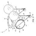
- FIG. 2 is a perspective view of the regulator valve and floats.
- FIG. 3 is a perspective view of the valve body.
- FIG. 4 is a perspective view of the valve member.
- FIG. 5 is a perspective view of a second embodiment with an added stop valve in the open position.
- FIG. 5A is the same as FIG. 5 with the added stop valve in the closed position.
- FIG. 6 is the same as FIG. 5 with the stop valve in an intermediate position.
- FIG. 7 is a perspective view.
- FIG. 8 is a plan view of FIG. 7 .
- FIG. 9 is a perspective view when in the gate closed position.
- FIG. 10 is a front view of the gate plate.
- FIG. 11 is a cross-sectional diagram of a channel in which the device is deployed.
- FIG. 12 is a perspective of the valve in FIG. 5 with a gate collar.
- network pipe 2 is 900 mm in diameter and branch pipe 4 brings water to the 1200-mm diameter tank 6 through a butterfly valve 8 past a flow meter 10 .
- the regulator valve 12 is bolted to the end of the branch pipe 4 and discharges into the tank.
- the valve body stem 14 is a T-shaped pipe of 320 mm diameter, the body being 510 mm long and the valve body stem 14 terminating in a connector ring 16 with bolt holes 18 for connection to the end of the branch pipe 4 .
- Both the body 20 and the valve member 22 ( FIG. 4 ) are made of stainless steel. Water enters the regulator valve 12 via the valve body stem 14 and discharges through the open ends of the body 20 . The flow through the valve is controlled by the valve member 22 , which is a sleeve of the same length as the valve body, namely 510 mm.
- the circumferential gap 24 is bridged by a trio of bearing strips 26 made of a slippery polymer and attached to the edge of the valve member by stainless steel fasteners (not shown).
- the strips are spaced at 120 degrees, enabling the member to rotate in the body with minimum friction.
- the crown of the valve member 22 has a cutout 28 with a straight edge 30 and tapered edges 32 extending over about 90 degrees of the circumference of the member.
- the cutout 28 lies in register with the connector ring 16 .
- the ends of the valve body 20 have pairs of slots 34 , 36 , 11 mm wide (see FIGS. 2, 3 and 5 ) extending 90 degrees around the quadrants facing the water below the valve body 20 .
- the slots 34 , 36 define the path of a pair of 10-mm diameter stainless steel rods 38 that are a slide fit in the slots.
- the rods pass through bores 39 near the edge of the valve member and are bent at one end into a foot 40 ( FIG. 2 ) that is secured to the valve member by a split pin 42 ( FIG. 2 ).
- the foot 40 is housed in the thickness of the valve member 22 and the end of the pin 42 rides in the slot in the valve body.
- each rod has a bore that receives a shackle 44 for connecting the arm to float chain 46 .
- the chain is about 600 mm long and runs through the shackle and is attached to itself.
- the chains each capture a spherical molded plastic float 48 .
- the floats are balanced by pivoted counterweights 50 .
- the chain 46 adjusts to suit the water level required. This allows for almost any water level required to be accommodated without affecting the functionality of the valve.
- the pipework In use, the pipework is installed and the valve is suspended above or within the operational range of water levels in the tank.
- the floats lie on the surface of the water and the counterweights rotate the valve body to the open position. As the land dries and the tank empties the floats lie on the tank floor.
- the meter When the operator opens the butterfly valve 8 , the meter begins to measure flow. The operator selects a suitable flow rate and the container allows inflow to feed the outflow pipes.
- the tank level rises and equilibrium is established. If the incoming flow fluctuates, the valve restores the equilibrium by rotating.
- valve It is not the purpose of the valve to halt flow. That is the task of the butterfly valve 8 .
- the valve ensures a constant head of water in the tank, whereby the irrigation proceeds in an orderly manner despite the fluctuations in the network.
- a head of 3 m to 5 m is usual in such networks, but this may spike to 10 m.
- FIGS. 5, 5A and 6 show valve body stem 14 is divided by a pair of square frame plates 52 , 54 .
- Plate 52 is attached to the valve body 20 .
- Plate 54 is attached to the part of the stem with the connector ring 16 .
- the gap 62 between the parallel plates 52 , 54 is bridged by pairs of gate guides 56 , 58 attached to the upright side edges of frame plates 52 , 54 .
- the gate gap 62 extends the full length of the guide.
- the gate itself is a modified M-shape made of steel sheet that is wider than the gate guides spacing and has two legs 64 , 66 joined by an upper part 68 with a convex leading edge 70 .
- the legs have slots 72 , 74 for reception of the pivoting connections 76 , 78 ( FIG. 7 ) of float arms 38 .
- the float arms 38 are fixed to the sleeve 22 to ensure that the floats exert the same uplift force as in the previous embodiment.
- the pivoting connections each have a central self-lubricating bush through which the float arm is free to slide in order to accommodate the linear rise and fall of the gate.
- the projection of the rods through the legs 64 , 66 is seen in FIGS. 6, 7 and 9 .
- the counterweights' mass is increased to adjust for the weight of the gate.
- the float arms lie in an intermediate position when the tank is both filling with network inflow and emptying into the irrigation pipes.
- the cutout 28 of sleeve 22 registers with the valve body stem 14 and, from this position, the floats quickly react to any increase in head. If the head persists, the floats press the gate into the closed position. As the tank drains, the floats descend. If the head has diminished, the gate may not reopen. If the tank drains further, the gate may reopen.
- FIG. 11 shows an irrigation channel 3 m to 4 m wide and 2 m deep that is fed by a steel pipe that brings pumped water from a bulk source such as a dam.
- the shape of the channel is as shown in FIG. 11 and the pipe is submerged so that the floats can exert flow control on the incoming water.
- the float-activated stop valve is connected to the external delivery conduit by ring flange 16 .
- Stem 14 is 300 mm in diameter and 700 mm long.
- the rise and fall gate straddles an incision (not shown) in the upper half of valve body stem 14 .
- the steel gate guides 56 , 58 are separated by gap 62 and welded to the outer surface of the valve body stem 14 . Gate gap 62 extends the full length of the guides.
- the gate itself (see FIG. 10 ) is a modified M-shape, made of stainless steel that is wider than the width of the gate guides and has two legs 64 , 66 joined by an upper part 68 with a convex leading edge 70 .
- the legs have slots 72 , 74 for the reception of the pivoting connections 76 , 78 of float arms or rods 38 .
- the guides 56 , 58 have pairs of slots 77 adjacent gate gap 62 in order to support the screws of pairs of vertical self-lubricating polymer strips 79 .
- the slots 77 allow accurate adjustment of gap 62 size leading to smooth motion of the gate.
- Upper part 68 supports a semi-circular collar 80 , 25 mm wide, which overlies the incision when the gate is closed. In the closed position, the convex leading edge 70 contacts the circular wall of the stem.
- the 22.5 degree rotary motion of the float arms 38 is made possible by the horizontal transverse pivots 82 welded to the outside wall of the valve body stem 14 .
- the counterweights and floats work in the same way as described in related Australian Patent Application Serial No. 2013902805.
- the water flow passes between the parallel float arms.
- the leading edge 70 closes the duct by descending to contact the lower cylindrical wall of the valve body stem 14 .
- the semi-circular collar 80 then rests on the upper part of the same wall.
Landscapes
- Engineering & Computer Science (AREA)
- General Engineering & Computer Science (AREA)
- Mechanical Engineering (AREA)
- Civil Engineering (AREA)
- Structural Engineering (AREA)
- Float Valves (AREA)
- Sliding Valves (AREA)
- Indicating Or Recording The Presence, Absence, Or Direction Of Movement (AREA)
Applications Claiming Priority (7)
| Application Number | Priority Date | Filing Date | Title |
|---|---|---|---|
| AU2013902571 | 2013-07-12 | ||
| AU2013902571A AU2013902571A0 (en) | 2013-07-12 | Irrigation Network Valve | |
| AU2013902805A AU2013902805A0 (en) | 2013-07-29 | Irrigation Network Valve | |
| AU2013902805 | 2013-07-29 | ||
| AU2013903986 | 2013-10-16 | ||
| AU2013903986A AU2013903986A0 (en) | 2013-10-16 | Irrigation Network Valve | |
| PCT/AU2014/000711 WO2015003217A1 (fr) | 2013-07-12 | 2014-07-11 | Vanne de réseau d'irrigation |
Publications (2)
| Publication Number | Publication Date |
|---|---|
| US20160138236A1 US20160138236A1 (en) | 2016-05-19 |
| US9850635B2 true US9850635B2 (en) | 2017-12-26 |
Family
ID=52279227
Family Applications (1)
| Application Number | Title | Priority Date | Filing Date |
|---|---|---|---|
| US14/904,397 Active 2034-12-23 US9850635B2 (en) | 2013-07-12 | 2014-07-11 | Irrigation network valve |
Country Status (9)
| Country | Link |
|---|---|
| US (1) | US9850635B2 (fr) |
| EP (2) | EP3019782A4 (fr) |
| JP (1) | JP6454700B2 (fr) |
| CN (1) | CN105745480B (fr) |
| AU (1) | AU2014289970B2 (fr) |
| DE (2) | DE14823167T9 (fr) |
| ES (1) | ES2701602T1 (fr) |
| NZ (1) | NZ716718A (fr) |
| WO (1) | WO2015003217A1 (fr) |
Cited By (1)
| Publication number | Priority date | Publication date | Assignee | Title |
|---|---|---|---|---|
| EP3763892A1 (fr) * | 2019-07-08 | 2021-01-13 | Stefan Sjöbert | Régulateur de débit |
Families Citing this family (7)
| Publication number | Priority date | Publication date | Assignee | Title |
|---|---|---|---|---|
| EP3019782A4 (fr) | 2013-07-12 | 2016-11-02 | Country Cocky Pty Ltd | Vanne de réseau d'irrigation |
| US10478871B2 (en) * | 2016-05-09 | 2019-11-19 | Lawrence Anthony Wiwi | Side-opening sleeve valve |
| CN105840906B (zh) * | 2016-06-08 | 2017-12-12 | 晋江佶邦机械技术服务有限公司 | 一种延时补水浮球阀及应用该种浮球阀的电开水器 |
| CN105972301A (zh) * | 2016-06-24 | 2016-09-28 | 戴文平 | 可调节双门异向限流阀 |
| CN107750908B (zh) * | 2017-11-21 | 2023-07-25 | 中国电建集团成都勘测设计研究院有限公司 | 集雨池及用于干旱地区的自动补水灌溉系统 |
| US11247754B1 (en) * | 2020-01-21 | 2022-02-15 | Marie Claire Fiala Amokrane | Water vessel flotation system |
| CN113699952A (zh) * | 2021-08-31 | 2021-11-26 | 宁波市农业技术推广总站 | 农田排水自动控制装置 |
Citations (23)
| Publication number | Priority date | Publication date | Assignee | Title |
|---|---|---|---|---|
| US747769A (en) * | 1903-06-22 | 1903-12-22 | Alanson L Richards | Automatic valve. |
| US948519A (en) * | 1910-02-08 | California Valve And Air Brake Company | Ball-cock valve and operating means therefor. | |
| US1343871A (en) | 1919-08-18 | 1920-06-15 | William H Lewis | Irrigation means |
| US1727082A (en) * | 1927-12-29 | 1929-09-03 | Rayfield Mfg Co | Float-controlled valve |
| US2314158A (en) * | 1942-03-10 | 1943-03-16 | Patrick Ernest Leimback | Control valve |
| US2362747A (en) | 1942-10-30 | 1944-11-14 | Duke Alfred | Irrigation system |
| US2904064A (en) * | 1957-05-08 | 1959-09-15 | Mace W Davis | Backwater valve |
| US3033226A (en) * | 1957-08-26 | 1962-05-08 | Valentine E Macy Jr | Valve |
| US3127909A (en) * | 1962-07-18 | 1964-04-07 | Honeywell Regulator Co | Rotary gate valve |
| JPS6132225A (ja) | 1984-07-23 | 1986-02-14 | Hitachi Ltd | 光方式記録再生装置 |
| US4797027A (en) * | 1986-06-13 | 1989-01-10 | Alsthom | Automatic level-regulating sluice |
| US4877352A (en) * | 1989-02-10 | 1989-10-31 | Waterman Industries, Inc. | Method and apparatus for control of an upstream water level |
| JPH02203089A (ja) | 1989-01-31 | 1990-08-13 | Katsuhiko Kosaka | 液面制御弁 |
| CN2161787Y (zh) | 1993-05-07 | 1994-04-13 | 何冠雄 | 垂直闸制式浮球自动阀 |
| FR2783891A1 (fr) | 1998-09-24 | 2000-03-31 | Jacques Duchazaubeneix | Regulateur de debit de liquide |
| US6305411B1 (en) | 2000-10-23 | 2001-10-23 | Ipex Inc. | Normally-open backwater valve |
| US6823890B1 (en) * | 2003-09-29 | 2004-11-30 | Biing-Yih Hwang | Water-intake control valve |
| US6953156B1 (en) | 2004-06-29 | 2005-10-11 | Boice Jr Nelson R | Irrigation method for sloping land |
| US7431264B2 (en) * | 2004-12-22 | 2008-10-07 | Michel Leroux | Knife gate valve |
| US20090120511A1 (en) | 2007-11-13 | 2009-05-14 | Bermad Cs Ltd. | Standpipe direct float valve |
| US7584939B2 (en) * | 2004-12-08 | 2009-09-08 | Steinhardt Gmbh | Surge flushing device for wastewater channels and the like |
| JP2010078224A (ja) | 2008-09-26 | 2010-04-08 | Hitachi Appliances Inc | フロート弁及び該フロート弁を備える冷凍機 |
| WO2015003217A1 (fr) | 2013-07-12 | 2015-01-15 | Country Cocky Pty. Ltd. | Vanne de réseau d'irrigation |
Family Cites Families (4)
| Publication number | Priority date | Publication date | Assignee | Title |
|---|---|---|---|---|
| JPS51144839U (fr) * | 1975-05-16 | 1976-11-20 | ||
| JPS6132225U (ja) * | 1984-07-30 | 1986-02-26 | 光男 間宮 | 自動除塵給水機 |
| JP2002335781A (ja) * | 2001-05-21 | 2002-11-26 | Yuichi Tanaka | 水位調節弁 |
| KR101033015B1 (ko) * | 2008-07-16 | 2011-05-09 | 김성환 | 하수로 차집관거의 토사유입 방지장치 |
-
2014
- 2014-07-11 EP EP14823167.3A patent/EP3019782A4/fr not_active Withdrawn
- 2014-07-11 AU AU2014289970A patent/AU2014289970B2/en active Active
- 2014-07-11 DE DE14823167.3T patent/DE14823167T9/de active Active
- 2014-07-11 JP JP2016524631A patent/JP6454700B2/ja active Active
- 2014-07-11 US US14/904,397 patent/US9850635B2/en active Active
- 2014-07-11 EP EP18171903.0A patent/EP3382102A1/fr active Pending
- 2014-07-11 DE DE18171903.0T patent/DE18171903T1/de active Pending
- 2014-07-11 NZ NZ716718A patent/NZ716718A/en unknown
- 2014-07-11 WO PCT/AU2014/000711 patent/WO2015003217A1/fr not_active Ceased
- 2014-07-11 CN CN201480050555.5A patent/CN105745480B/zh active Active
- 2014-07-11 ES ES18171903T patent/ES2701602T1/es active Pending
Patent Citations (24)
| Publication number | Priority date | Publication date | Assignee | Title |
|---|---|---|---|---|
| US948519A (en) * | 1910-02-08 | California Valve And Air Brake Company | Ball-cock valve and operating means therefor. | |
| US747769A (en) * | 1903-06-22 | 1903-12-22 | Alanson L Richards | Automatic valve. |
| US1343871A (en) | 1919-08-18 | 1920-06-15 | William H Lewis | Irrigation means |
| US1727082A (en) * | 1927-12-29 | 1929-09-03 | Rayfield Mfg Co | Float-controlled valve |
| US2314158A (en) * | 1942-03-10 | 1943-03-16 | Patrick Ernest Leimback | Control valve |
| US2362747A (en) | 1942-10-30 | 1944-11-14 | Duke Alfred | Irrigation system |
| US2904064A (en) * | 1957-05-08 | 1959-09-15 | Mace W Davis | Backwater valve |
| US3033226A (en) * | 1957-08-26 | 1962-05-08 | Valentine E Macy Jr | Valve |
| US3127909A (en) * | 1962-07-18 | 1964-04-07 | Honeywell Regulator Co | Rotary gate valve |
| JPS6132225A (ja) | 1984-07-23 | 1986-02-14 | Hitachi Ltd | 光方式記録再生装置 |
| US4797027A (en) * | 1986-06-13 | 1989-01-10 | Alsthom | Automatic level-regulating sluice |
| JPH02203089A (ja) | 1989-01-31 | 1990-08-13 | Katsuhiko Kosaka | 液面制御弁 |
| US4877352A (en) * | 1989-02-10 | 1989-10-31 | Waterman Industries, Inc. | Method and apparatus for control of an upstream water level |
| CN2161787Y (zh) | 1993-05-07 | 1994-04-13 | 何冠雄 | 垂直闸制式浮球自动阀 |
| FR2783891A1 (fr) | 1998-09-24 | 2000-03-31 | Jacques Duchazaubeneix | Regulateur de debit de liquide |
| US6305411B1 (en) | 2000-10-23 | 2001-10-23 | Ipex Inc. | Normally-open backwater valve |
| US6823890B1 (en) * | 2003-09-29 | 2004-11-30 | Biing-Yih Hwang | Water-intake control valve |
| US6953156B1 (en) | 2004-06-29 | 2005-10-11 | Boice Jr Nelson R | Irrigation method for sloping land |
| US7584939B2 (en) * | 2004-12-08 | 2009-09-08 | Steinhardt Gmbh | Surge flushing device for wastewater channels and the like |
| US7431264B2 (en) * | 2004-12-22 | 2008-10-07 | Michel Leroux | Knife gate valve |
| US20090120511A1 (en) | 2007-11-13 | 2009-05-14 | Bermad Cs Ltd. | Standpipe direct float valve |
| IL188274A (en) | 2007-11-13 | 2012-05-31 | Bermad Cs Ltd | Standpipe direct float valve |
| JP2010078224A (ja) | 2008-09-26 | 2010-04-08 | Hitachi Appliances Inc | フロート弁及び該フロート弁を備える冷凍機 |
| WO2015003217A1 (fr) | 2013-07-12 | 2015-01-15 | Country Cocky Pty. Ltd. | Vanne de réseau d'irrigation |
Non-Patent Citations (2)
| Title |
|---|
| PCT International Search Report dated Aug. 11, 2014, PCT/AU2014/000711. |
| PCT Written Opinion dated Aug. 11, 2014, PCT/AU2014/000711. |
Cited By (1)
| Publication number | Priority date | Publication date | Assignee | Title |
|---|---|---|---|---|
| EP3763892A1 (fr) * | 2019-07-08 | 2021-01-13 | Stefan Sjöbert | Régulateur de débit |
Also Published As
| Publication number | Publication date |
|---|---|
| EP3382102A1 (fr) | 2018-10-03 |
| JP6454700B2 (ja) | 2019-01-16 |
| EP3019782A1 (fr) | 2016-05-18 |
| JP2016529449A (ja) | 2016-09-23 |
| DE18171903T1 (de) | 2019-02-28 |
| AU2014289970B2 (en) | 2019-04-04 |
| DE14823167T9 (de) | 2018-03-08 |
| NZ716718A (en) | 2019-08-30 |
| EP3019782A4 (fr) | 2016-11-02 |
| CN105745480B (zh) | 2018-02-13 |
| US20160138236A1 (en) | 2016-05-19 |
| AU2014289970A1 (en) | 2016-02-25 |
| WO2015003217A1 (fr) | 2015-01-15 |
| DE14823167T1 (de) | 2016-07-28 |
| ES2701602T1 (es) | 2019-02-25 |
| CN105745480A (zh) | 2016-07-06 |
Similar Documents
| Publication | Publication Date | Title |
|---|---|---|
| US9850635B2 (en) | Irrigation network valve | |
| US7942606B2 (en) | Groundwater control system with automatic water flow regulator | |
| US4305426A (en) | Apparatus for continuous constant discharge of liquid from a container | |
| US2362747A (en) | Irrigation system | |
| US9363956B1 (en) | Multiple-line irrigation system and method | |
| US10362728B2 (en) | Flow diverter for a fertilization system | |
| US8720803B1 (en) | Multiple-line irrigation system and method | |
| US3797253A (en) | Automatic irrigation system | |
| BR112012018739B1 (pt) | Sistema de bebedouro para aves | |
| CN112203775B (zh) | 章动液体排放设备及其与抗章动适配套件的组合 | |
| US3951163A (en) | Automatic anti-siphon valve | |
| US6216733B1 (en) | Apparatus for the distribution of water or other liquids | |
| HK1226468A1 (en) | Shut-off valve and a composition of flow regulator and shut-off valve | |
| HK1226468B (en) | Shut-off valve and a composition of flow regulator and shut-off valve | |
| KR101625929B1 (ko) | 계획 급수량에 따른 저수조의 용수 균등 공급장치 | |
| JP2016054708A (ja) | 水位調整機構 | |
| US1220092A (en) | Apparatus for separating fluid-suspended material. | |
| CN118749335B (zh) | 一种辣椒种植培育架体装置 | |
| US2509122A (en) | Mixing device | |
| TH2103003825C3 (th) | โครงสร้างหัวจ่ายน้ำแบบปรับความสูงในแนวดิ่งและปรับความยาวในแนวนอนได้ | |
| RU2300188C1 (ru) | Водовыпуск поливного трубопровода систем капельного орошения | |
| RU2579476C1 (ru) | Капельный водовыпуск | |
| SU1287792A1 (ru) | Поливное устройство | |
| RU2616374C1 (ru) | Устройство для подпочвенного орошения при выращивании влаголюбивых растений | |
| RU2636319C1 (ru) | Регулятор дренажного стока |
Legal Events
| Date | Code | Title | Description |
|---|---|---|---|
| AS | Assignment |
Owner name: COUNTRY COCKY PTY. LTD., AUSTRALIA Free format text: ASSIGNMENT OF ASSIGNORS INTEREST;ASSIGNOR:COCCIARDI, PETER ANTHONY;REEL/FRAME:038746/0762 Effective date: 20160316 |
|
| STCF | Information on status: patent grant |
Free format text: PATENTED CASE |
|
| MAFP | Maintenance fee payment |
Free format text: PAYMENT OF MAINTENANCE FEE, 4TH YR, SMALL ENTITY (ORIGINAL EVENT CODE: M2551); ENTITY STATUS OF PATENT OWNER: SMALL ENTITY Year of fee payment: 4 |
|
| MAFP | Maintenance fee payment |
Free format text: PAYMENT OF MAINTENANCE FEE, 8TH YR, SMALL ENTITY (ORIGINAL EVENT CODE: M2552); ENTITY STATUS OF PATENT OWNER: SMALL ENTITY Year of fee payment: 8 |