US9855129B2 - Multi-level suture attachments for coupling a stent to graft material - Google Patents
Multi-level suture attachments for coupling a stent to graft material Download PDFInfo
- Publication number
- US9855129B2 US9855129B2 US14/062,167 US201314062167A US9855129B2 US 9855129 B2 US9855129 B2 US 9855129B2 US 201314062167 A US201314062167 A US 201314062167A US 9855129 B2 US9855129 B2 US 9855129B2
- Authority
- US
- United States
- Prior art keywords
- suture
- stent
- bore
- graft
- distal
- Prior art date
- Legal status (The legal status is an assumption and is not a legal conclusion. Google has not performed a legal analysis and makes no representation as to the accuracy of the status listed.)
- Active, expires
Links
Images


Classifications
-
- A—HUMAN NECESSITIES
- A61—MEDICAL OR VETERINARY SCIENCE; HYGIENE
- A61F—FILTERS IMPLANTABLE INTO BLOOD VESSELS; PROSTHESES; DEVICES PROVIDING PATENCY TO, OR PREVENTING COLLAPSING OF, TUBULAR STRUCTURES OF THE BODY, e.g. STENTS; ORTHOPAEDIC, NURSING OR CONTRACEPTIVE DEVICES; FOMENTATION; TREATMENT OR PROTECTION OF EYES OR EARS; BANDAGES, DRESSINGS OR ABSORBENT PADS; FIRST-AID KITS
- A61F2/00—Filters implantable into blood vessels; Prostheses, i.e. artificial substitutes or replacements for parts of the body; Appliances for connecting them with the body; Devices providing patency to, or preventing collapsing of, tubular structures of the body, e.g. stents
- A61F2/02—Prostheses implantable into the body
- A61F2/04—Hollow or tubular parts of organs, e.g. bladders, tracheae, bronchi or bile ducts
- A61F2/06—Blood vessels
-
- A—HUMAN NECESSITIES
- A61—MEDICAL OR VETERINARY SCIENCE; HYGIENE
- A61F—FILTERS IMPLANTABLE INTO BLOOD VESSELS; PROSTHESES; DEVICES PROVIDING PATENCY TO, OR PREVENTING COLLAPSING OF, TUBULAR STRUCTURES OF THE BODY, e.g. STENTS; ORTHOPAEDIC, NURSING OR CONTRACEPTIVE DEVICES; FOMENTATION; TREATMENT OR PROTECTION OF EYES OR EARS; BANDAGES, DRESSINGS OR ABSORBENT PADS; FIRST-AID KITS
- A61F2/00—Filters implantable into blood vessels; Prostheses, i.e. artificial substitutes or replacements for parts of the body; Appliances for connecting them with the body; Devices providing patency to, or preventing collapsing of, tubular structures of the body, e.g. stents
- A61F2/02—Prostheses implantable into the body
- A61F2/04—Hollow or tubular parts of organs, e.g. bladders, tracheae, bronchi or bile ducts
- A61F2/06—Blood vessels
- A61F2/07—Stent-grafts
-
- A—HUMAN NECESSITIES
- A61—MEDICAL OR VETERINARY SCIENCE; HYGIENE
- A61F—FILTERS IMPLANTABLE INTO BLOOD VESSELS; PROSTHESES; DEVICES PROVIDING PATENCY TO, OR PREVENTING COLLAPSING OF, TUBULAR STRUCTURES OF THE BODY, e.g. STENTS; ORTHOPAEDIC, NURSING OR CONTRACEPTIVE DEVICES; FOMENTATION; TREATMENT OR PROTECTION OF EYES OR EARS; BANDAGES, DRESSINGS OR ABSORBENT PADS; FIRST-AID KITS
- A61F2/00—Filters implantable into blood vessels; Prostheses, i.e. artificial substitutes or replacements for parts of the body; Appliances for connecting them with the body; Devices providing patency to, or preventing collapsing of, tubular structures of the body, e.g. stents
- A61F2/82—Devices providing patency to, or preventing collapsing of, tubular structures of the body, e.g. stents
- A61F2/86—Stents in a form characterised by the wire-like elements; Stents in the form characterised by a net-like or mesh-like structure
- A61F2/90—Stents in a form characterised by the wire-like elements; Stents in the form characterised by a net-like or mesh-like structure characterised by a net-like or mesh-like structure
- A61F2/91—Stents in a form characterised by the wire-like elements; Stents in the form characterised by a net-like or mesh-like structure characterised by a net-like or mesh-like structure made from perforated sheets or tubes, e.g. perforated by laser cuts or etched holes
-
- A—HUMAN NECESSITIES
- A61—MEDICAL OR VETERINARY SCIENCE; HYGIENE
- A61F—FILTERS IMPLANTABLE INTO BLOOD VESSELS; PROSTHESES; DEVICES PROVIDING PATENCY TO, OR PREVENTING COLLAPSING OF, TUBULAR STRUCTURES OF THE BODY, e.g. STENTS; ORTHOPAEDIC, NURSING OR CONTRACEPTIVE DEVICES; FOMENTATION; TREATMENT OR PROTECTION OF EYES OR EARS; BANDAGES, DRESSINGS OR ABSORBENT PADS; FIRST-AID KITS
- A61F2/00—Filters implantable into blood vessels; Prostheses, i.e. artificial substitutes or replacements for parts of the body; Appliances for connecting them with the body; Devices providing patency to, or preventing collapsing of, tubular structures of the body, e.g. stents
- A61F2/95—Instruments specially adapted for placement or removal of stents or stent-grafts
-
- A—HUMAN NECESSITIES
- A61—MEDICAL OR VETERINARY SCIENCE; HYGIENE
- A61F—FILTERS IMPLANTABLE INTO BLOOD VESSELS; PROSTHESES; DEVICES PROVIDING PATENCY TO, OR PREVENTING COLLAPSING OF, TUBULAR STRUCTURES OF THE BODY, e.g. STENTS; ORTHOPAEDIC, NURSING OR CONTRACEPTIVE DEVICES; FOMENTATION; TREATMENT OR PROTECTION OF EYES OR EARS; BANDAGES, DRESSINGS OR ABSORBENT PADS; FIRST-AID KITS
- A61F2/00—Filters implantable into blood vessels; Prostheses, i.e. artificial substitutes or replacements for parts of the body; Appliances for connecting them with the body; Devices providing patency to, or preventing collapsing of, tubular structures of the body, e.g. stents
- A61F2/82—Devices providing patency to, or preventing collapsing of, tubular structures of the body, e.g. stents
- A61F2/848—Devices providing patency to, or preventing collapsing of, tubular structures of the body, e.g. stents having means for fixation to the vessel wall, e.g. barbs
-
- A—HUMAN NECESSITIES
- A61—MEDICAL OR VETERINARY SCIENCE; HYGIENE
- A61F—FILTERS IMPLANTABLE INTO BLOOD VESSELS; PROSTHESES; DEVICES PROVIDING PATENCY TO, OR PREVENTING COLLAPSING OF, TUBULAR STRUCTURES OF THE BODY, e.g. STENTS; ORTHOPAEDIC, NURSING OR CONTRACEPTIVE DEVICES; FOMENTATION; TREATMENT OR PROTECTION OF EYES OR EARS; BANDAGES, DRESSINGS OR ABSORBENT PADS; FIRST-AID KITS
- A61F2/00—Filters implantable into blood vessels; Prostheses, i.e. artificial substitutes or replacements for parts of the body; Appliances for connecting them with the body; Devices providing patency to, or preventing collapsing of, tubular structures of the body, e.g. stents
- A61F2/02—Prostheses implantable into the body
- A61F2/04—Hollow or tubular parts of organs, e.g. bladders, tracheae, bronchi or bile ducts
- A61F2/06—Blood vessels
- A61F2/07—Stent-grafts
- A61F2002/075—Stent-grafts the stent being loosely attached to the graft material, e.g. by stitching
-
- A—HUMAN NECESSITIES
- A61—MEDICAL OR VETERINARY SCIENCE; HYGIENE
- A61F—FILTERS IMPLANTABLE INTO BLOOD VESSELS; PROSTHESES; DEVICES PROVIDING PATENCY TO, OR PREVENTING COLLAPSING OF, TUBULAR STRUCTURES OF THE BODY, e.g. STENTS; ORTHOPAEDIC, NURSING OR CONTRACEPTIVE DEVICES; FOMENTATION; TREATMENT OR PROTECTION OF EYES OR EARS; BANDAGES, DRESSINGS OR ABSORBENT PADS; FIRST-AID KITS
- A61F2/00—Filters implantable into blood vessels; Prostheses, i.e. artificial substitutes or replacements for parts of the body; Appliances for connecting them with the body; Devices providing patency to, or preventing collapsing of, tubular structures of the body, e.g. stents
- A61F2/82—Devices providing patency to, or preventing collapsing of, tubular structures of the body, e.g. stents
- A61F2/848—Devices providing patency to, or preventing collapsing of, tubular structures of the body, e.g. stents having means for fixation to the vessel wall, e.g. barbs
- A61F2002/8486—Devices providing patency to, or preventing collapsing of, tubular structures of the body, e.g. stents having means for fixation to the vessel wall, e.g. barbs provided on at least one of the ends
-
- A—HUMAN NECESSITIES
- A61—MEDICAL OR VETERINARY SCIENCE; HYGIENE
- A61F—FILTERS IMPLANTABLE INTO BLOOD VESSELS; PROSTHESES; DEVICES PROVIDING PATENCY TO, OR PREVENTING COLLAPSING OF, TUBULAR STRUCTURES OF THE BODY, e.g. STENTS; ORTHOPAEDIC, NURSING OR CONTRACEPTIVE DEVICES; FOMENTATION; TREATMENT OR PROTECTION OF EYES OR EARS; BANDAGES, DRESSINGS OR ABSORBENT PADS; FIRST-AID KITS
- A61F2/00—Filters implantable into blood vessels; Prostheses, i.e. artificial substitutes or replacements for parts of the body; Appliances for connecting them with the body; Devices providing patency to, or preventing collapsing of, tubular structures of the body, e.g. stents
- A61F2/95—Instruments specially adapted for placement or removal of stents or stent-grafts
- A61F2002/9505—Instruments specially adapted for placement or removal of stents or stent-grafts having retaining means other than an outer sleeve, e.g. male-female connector between stent and instrument
- A61F2002/9511—Instruments specially adapted for placement or removal of stents or stent-grafts having retaining means other than an outer sleeve, e.g. male-female connector between stent and instrument the retaining means being filaments or wires
-
- A—HUMAN NECESSITIES
- A61—MEDICAL OR VETERINARY SCIENCE; HYGIENE
- A61F—FILTERS IMPLANTABLE INTO BLOOD VESSELS; PROSTHESES; DEVICES PROVIDING PATENCY TO, OR PREVENTING COLLAPSING OF, TUBULAR STRUCTURES OF THE BODY, e.g. STENTS; ORTHOPAEDIC, NURSING OR CONTRACEPTIVE DEVICES; FOMENTATION; TREATMENT OR PROTECTION OF EYES OR EARS; BANDAGES, DRESSINGS OR ABSORBENT PADS; FIRST-AID KITS
- A61F2/00—Filters implantable into blood vessels; Prostheses, i.e. artificial substitutes or replacements for parts of the body; Appliances for connecting them with the body; Devices providing patency to, or preventing collapsing of, tubular structures of the body, e.g. stents
- A61F2/95—Instruments specially adapted for placement or removal of stents or stent-grafts
- A61F2/962—Instruments specially adapted for placement or removal of stents or stent-grafts having an outer sleeve
- A61F2/966—Instruments specially adapted for placement or removal of stents or stent-grafts having an outer sleeve with relative longitudinal movement between outer sleeve and prosthesis, e.g. using a push rod
- A61F2002/9665—Instruments specially adapted for placement or removal of stents or stent-grafts having an outer sleeve with relative longitudinal movement between outer sleeve and prosthesis, e.g. using a push rod with additional retaining means
-
- A—HUMAN NECESSITIES
- A61—MEDICAL OR VETERINARY SCIENCE; HYGIENE
- A61F—FILTERS IMPLANTABLE INTO BLOOD VESSELS; PROSTHESES; DEVICES PROVIDING PATENCY TO, OR PREVENTING COLLAPSING OF, TUBULAR STRUCTURES OF THE BODY, e.g. STENTS; ORTHOPAEDIC, NURSING OR CONTRACEPTIVE DEVICES; FOMENTATION; TREATMENT OR PROTECTION OF EYES OR EARS; BANDAGES, DRESSINGS OR ABSORBENT PADS; FIRST-AID KITS
- A61F2220/00—Fixations or connections for prostheses classified in groups A61F2/00 - A61F2/26 or A61F2/82 or A61F9/00 or A61F11/00 or subgroups thereof
- A61F2220/0008—Fixation appliances for connecting prostheses to the body
- A61F2220/0016—Fixation appliances for connecting prostheses to the body with sharp anchoring protrusions, e.g. barbs, pins, spikes
-
- A—HUMAN NECESSITIES
- A61—MEDICAL OR VETERINARY SCIENCE; HYGIENE
- A61F—FILTERS IMPLANTABLE INTO BLOOD VESSELS; PROSTHESES; DEVICES PROVIDING PATENCY TO, OR PREVENTING COLLAPSING OF, TUBULAR STRUCTURES OF THE BODY, e.g. STENTS; ORTHOPAEDIC, NURSING OR CONTRACEPTIVE DEVICES; FOMENTATION; TREATMENT OR PROTECTION OF EYES OR EARS; BANDAGES, DRESSINGS OR ABSORBENT PADS; FIRST-AID KITS
- A61F2220/00—Fixations or connections for prostheses classified in groups A61F2/00 - A61F2/26 or A61F2/82 or A61F9/00 or A61F11/00 or subgroups thereof
- A61F2220/0025—Connections or couplings between prosthetic parts, e.g. between modular parts; Connecting elements
- A61F2220/0075—Connections or couplings between prosthetic parts, e.g. between modular parts; Connecting elements sutured, ligatured or stitched, retained or tied with a rope, string, thread, wire or cable
Definitions
- the present embodiments relate generally to apparatus and methods for treating medical conditions, and more specifically, to stent-grafts for use in body vessels to treat those medical conditions.
- Stents may be inserted into an anatomical vessel or duct for various purposes. Stents may maintain or restore patency in a formerly blocked or constricted passageway, for example, following a balloon angioplasty procedure. Other stents may be used for different procedures, for example, stents placed in or about a graft have been used to hold the graft in an open configuration to treat an aneurysm. Additionally, stents coupled to one or both ends of a graft may extend proximally or distally away from the graft to engage a healthy portion of a vessel wall away from a diseased portion of an aneurysm to provide endovascular graft fixation.
- Stents may be either self-expanding or balloon-expandable, or they can have characteristics of both types of stents.
- Self-expanding stents may be delivered to a target site in a compressed configuration and subsequently expanded by removing a delivery sheath, removing trigger wires and/or releasing diameter reducing ties. With self-expanding stents, the stents expand primarily based on their own expansive force without the need for further mechanical expansion.
- the shape-memory alloy may be employed to cause the stent to return to a predetermined configuration upon removal of the sheath or other device maintaining the stent in its predeployment configuration.
- sutures are commonly threaded between a portion of the stent and the graft to provide a secure engagement. If multiple sutures are provided, safety may be increased in the event a suture breaks. However, the provision of multiple sutures can increase the overall amount of material used, which may arise in a larger profile when compressed in the delivery configuration. A larger delivery profile may reduce the overall number of patients who can be treated with such stent-grafts.
- a stent has proximal and distal ends, a plurality of strut segments disposed between the proximal and distal ends that enable expansion of the stent from a compressed state to a deployed state, and a series of distal apices disposed at the distal end of the stent. At least a portion of a first distal apex overlaps with graft material. First and second sutures are each coupled between a portion of the first distal apex and the graft material. The first and second sutures are positioned at different longitudinal zones that lack an axial overlap with one another.
- a first suture bore is formed in the first distal apex, and the first suture is looped through at least the first suture bore and the graft material.
- the second suture may be looped through the first suture bore and the graft material, in a manner such that the first and second sutures extend away from the first suture bore in different axial directions.
- a second suture bore may be formed in the first distal apex, and the second suture may be looped through at least the second suture bore and the graft material. The second suture further may be looped between the first and second suture bores.
- an imaging bore may be positioned proximal to the first suture bore and distal to the second suture bore. The first suture bore and at least a portion of the imaging bore may overlap with the graft material, and the second suture bore may be disposed at least partially beyond a proximal edge of the graft material.
- At least one barb may be integrally formed in a surface of the first distal apex at a location proximal to the imaging bore.
- the imaging bore may be disposed at the location corresponding to an endpoint of the proximal edge of the graft material.
- At least one suture extends around a proximal edge of the graft material to reduce the potential for infolding at the proximal edge.
- FIG. 1 is a side view of a portion of a stent-graft having a stent coupled to a proximal region of a graft material in accordance with a first embodiment.
- FIG. 2 is a perspective view of distal apices of the stent of FIG. 1 .
- FIG. 3 is an enlarged side view of an interface between the distal apices of the stent and the proximal region of the graft material of FIG. 1 .
- FIG. 4 is a side view of an alternative interface between distal apices of a stent and a proximal region of a graft material.
- FIG. 5 is a side view of a further alternative interface between distal apices of a stent and a proximal region of a graft material.
- FIG. 6 is a side view of yet a further alternative interface between distal apices of a stent and a proximal region of a graft material.
- FIG. 7 is a side view of yet a further alternative interface between distal apices of a stent and a proximal region of a graft material.
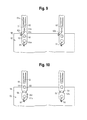
- FIG. 9 is a side view of yet a further alternative interface between distal apices of a stent and a proximal region of a graft material.
- FIG. 10 is a side view of yet a further alternative interface between distal apices of a stent and a proximal region of a graft material.
- proximal refers to a direction that is generally closest to the heart during a medical procedure
- distal refers to a direction that is furthest from the heart during a medical procedure
- a stent-graft 10 according to a first embodiment comprises a stent 20 and a graft material 92 .
- the stent 20 may be manufactured from a continuous cylinder into which a pattern may be cut by a laser or by chemical etching to produce slits in the wall of the cylinder. The resulting structure may then be heat set to give it a desired final configuration.
- the proximal end of the stent 20 may comprise multiple adjacent proximal apices 22 a and 22 b
- the distal end of the stent 20 may comprise multiple adjacent distal apices 62 , as shown in FIG. 1 .
- At least one pair of adjacent, proximal apices 22 a and 22 b comprises different features.
- a first proximal apex 22 a may comprise an end region 30 having a bore 31 formed therein, wherein the bore 31 is configured to receive a trigger wire.
- a second, adjacent proximal apex 22 b comprises an end region 40 having an integral barb 42 formed therein, as shown in FIG. 1 .
- the second proximal apex 22 b is not configured to be restrained using a trigger wire.
- the barbs 42 disposed in at least one of the end regions 40 of the second proximal apices 22 b may be formed by laser cutting a desired barb shape into the end regions 40 .
- a slit 41 therefore is formed into each end region 40 after the desired barb shape is formed, as shown in FIG. 1 .
- a main body of the barb 42 may be bent in a radially outward direction with respect to the end region 40 .
- the angle may comprise any acute angle, or alternatively may be substantially orthogonal or obtuse.
- the barbs 42 may be sharpened, for example, by grinding the tip of the barb, to facilitate engagement at a target tissue site.
- Expansion of the stent 20 is at least partly provided by the angled strut segments 57 and 58 , which may be substantially parallel to one another in a compressed state, but may tend to bow outward away from one another in the expanded state shown in FIG. 1 .
- the first and second angled strut segments 57 and 58 may be disposed at an angle of about 20-60 degrees relative to the longitudinal axis of the stent 20 , as depicted in FIG. 1 .
- the stent 20 may be manufactured from a super-elastic material.
- the super-elastic material may comprise a shape-memory alloy, such as a nickel titanium alloy (nitinol).
- the stent 20 comprises a self-expanding material such as nitinol, the stent may be heat-set into the desired expanded state, whereby the stent 20 can assume a relaxed configuration in which it assumes the preconfigured first expanded inner diameter upon application of a certain cold or hot medium.
- the stent 20 may be made from other metals and alloys that allow the stent 20 to return to its original, expanded configuration upon deployment, without inducing a permanent strain on the material due to compression.
- the stent 20 may comprise other materials such as stainless steel, cobalt-chrome alloys, amorphous metals, tantalum, platinum, gold and titanium.
- the stent 20 also may be made from non-metallic materials, such as thermoplastics and other polymers.
- Each of distal apices 62 may be coupled to the graft material 92 , for example, using one or more sutures that are looped through the graft material 92 and bores of the stent 20 , as described further below.
- the stent 20 may be used as an attachment stent for endovascular graft fixation.
- the graft material 92 may overlap with an aneurysm to seal off fluid flow into the aneurysm, while the proximal end of the stent 20 may extend in a proximal direction away from the graft material 92 , e.g., to engage a healthy portion of a vessel wall away from a diseased portion of the aneurysm.
- each of the distal apices 62 comprises first and second suture bores 61 a and 61 b that are adapted to receive a suture for coupling the distal end of the stent 20 to the graft material 92 .
- Each of the distal apices 62 may also comprise an imaging bore 90 adapted to receive a suitable radiopaque marker 91 , such as a gold marker.
- the imaging bore 90 may be beveled, or alternatively, may be substantially orthogonal to the strut of the distal apex 62 . It is noted that FIG. 2 shows an imaging bore 90 where a marker has yet to be placed therein, while FIG. 3 shows the imaging bore 90 with the marker 91 secured therein.
- a physician may know exactly where the proximal edge 94 of the graft material 92 is being placed because he or she can view the position of the radiopaque markers in the imaging bores 90 . Therefore, the chances of inadvertently overlapping the graft material 92 with a branch vessel, or another undesired location, may be reduced.
- one or more of the distal apices 62 of the stent 20 may comprise at least one barb 52 .
- the at least one barb 52 is disposed proximal to each of the first and second suture bores 61 a and 61 b , and also proximal to the imaging bore 90 .
- the at least one barb 52 may be formed integrally with its respective distal apex 62 , e.g., by forming a slit 51 in the distal apex in the manner described above for the barbs 42 , or alternately may comprise a barb that is externally secured to the distal apex 90 .
- the imaging bore 90 is disposed between the first and second suture bores 61 a and 61 b , as shown in FIGS. 1-3 . While the imaging bore 90 is shown as being aligned just distal to a proximal end 94 of the graft material 92 in FIG. 3 , the imaging bore 90 alternatively may be aligned precisely with the proximal end 94 of the graft material 92 .
- the stent-graft 10 of FIGS. 1-3 further comprises at least first and second sutures 81 and 82 .
- the first suture 81 is looped between the first suture bore 61 a and the graft material 92
- the second suture 82 is looped between the first and second suture bores 61 a and 62 b and trough the graft material 92 , as best seen in FIG. 3 .
- the second suture 82 may extend longitudinally over the imaging bore 90 as it extends between the first and second suture bores 61 a and 62 , in the instance in which the imaging bore 90 is positioned between the first and second suture bores 61 a and 62 .
- the first and second sutures 81 and 82 may be threaded through the graft material 92 and securely knotted.
- the sutures 81 and 82 preferably are positioned at different longitudinal zones that lack an overlap with one another, thereby reducing the amount of suture material at any given longitudinal location, which may significantly reduce the delivery profile.
- the first suture 81 may be positioned through the first suture bore 61 a and extend distally therefrom in a manner that spans an axial length x 1
- the second suture 82 may be positioned through the first suture bore 61 a and extend proximally therefrom towards the second suture bore 61 b in a manner that spans an axial length x 2 , as shown in FIG. 3 .
- the first and second sutures 81 and 82 are not longitudinally overlapping with one another along the axial zones x 1 and x 2 .
- the stent-graft 10 may be suitable for delivery in a larger portion of the population, including those with relatively small vessels, via smaller delivery systems.
- knots of the suture loop can add undesirable bulk to the delivery profile of the stent-graft 10 , the knots of the first and second sutures 81 and 82 will not overlap with one another, since the first and second sutures 81 and 82 themselves are not longitudinally overlapping with one another along the axial zones x 1 and x 2 .
- the knot of the first suture 81 may be positioned in a distal direction, while the knot of the second suture 82 may be positioned in a proximal direction, as depicted in FIG. 3 , thereby further ensuring that these relatively bulky parts are not overlapping with one another.
- the knot of the second suture 82 may be disposed proximally beyond the proximal edge 94 of the graft material 92 , as shown in FIG. 3 , thereby further reducing the delivery profile by not having the suture knot overlap with the graft material 92 .
- infolding at the proximal edge 94 may be significantly reduced.
- at least the second sutures 82 is disposed around a portion of the proximal edge 94 of the graft material 92 , thereby preventing infolding of the graft material 92 at this location and surrounding areas.
- proximal apices of the Z-stent 15 alternatively may be aligned with the distal apices 62 of the stent 20 .
- FIGS. 4-10 various alternative embodiments of the interface between distal apices and graft material are shown and described, including alternative distal apex designs and/or suture attachments to the graft.
- the embodiment of FIG. 4 is similar to the embodiment of FIGS. 1-3 , with like reference numerals representing corresponding parts, with a main exception that one or more alternative distal apices 62 ′ comprises the first suture bore 61 a , but the second suture bore 61 b is omitted. Further, a modified second suture 82 ′ is coupled between the first suture bore 61 a and the proximal edge 94 of the graft material 92 , as shown in FIG. 4 .
- the second suture 82 ′ thus extends, in an angled manner, through the distal apex 62 at a distal location and laterally around a side of the distal apex 62 at a proximal location.
- the embodiment of FIG. 4 encompasses several advantages of the embodiment of FIGS.
- 1-3 including but not limited to the provision of at least two different sutures that are coupled between a single distal apex of the stent 20 and the graft material 92 for added safety in the event that one suture breaks, the positioning of at least two sutures at different longitudinal zones that lack an overlap with one another to reduce the amount of suture material at any given longitudinal location and reduce the delivery profile, the longitudinal offset of positioning of knots of different sutures, and the provision of at least one suture attachment at the proximal edge 94 of the graft material 92 to reduce the potential for infolding at the proximal edge 94 .
- this alternative embodiment is similar to the embodiment of FIG. 4 , with a main exception that while the modified second suture 82 ′ of FIG. 4 extends to the side of the distal apex 62 ′, in the embodiment of FIG. 5 a modified second suture 82 ′′ is coupled between the first suture bore 61 a and the proximal edge 94 of the graft material 92 and spans at least 360 degrees around the perimeter or width of the distal apex 62 ′.
- the embodiment of FIG. 5 encompasses at least the multiple advantages of the embodiments of FIGS. 1-3 and FIG. 4 , as explained above.
- this alternative embodiment is similar to the embodiment of FIGS. 1-3 , with a main exception that a third suture bore 61 c is provided.
- the first and second suture bores 61 a and 61 b , and the imaging bore 90 are each disposed distal to the proximal edge 94 of the graft material 92 , while the third suture bore 61 c is disposed at least partially beyond the proximal edge 94 .
- the second suture 82 is disposed between the second suture bore 61 b and the third suture bore 61 c .
- the embodiment of FIG. 6 encompasses at least the multiple advantages of the embodiments of FIGS. 1-3 , FIG. 4 and FIG. 5 , as explained above.
- this alternative embodiment is similar to the embodiment of FIGS. 4-5 , with a main exception that at least one alternative slit 51 ′ of the distal apex comprises a main width 51 a , a reduced width 51 b , and a coupling zone 51 c for receiving a portion of a second suture 82 b , which is looped through the coupling zone 51 c and the graft material 92 .
- the coupling zone 51 c may comprise a width that is larger than the reduced width 51 b , thereby ensuring that the second suture 82 b stays within the coupling zone 51 c and does not move proximally up the slit 51 ′.
- suture bores may be provided on any particular distal apex of the stent.
Landscapes
- Health & Medical Sciences (AREA)
- Engineering & Computer Science (AREA)
- Biomedical Technology (AREA)
- Cardiology (AREA)
- Oral & Maxillofacial Surgery (AREA)
- Transplantation (AREA)
- Heart & Thoracic Surgery (AREA)
- Vascular Medicine (AREA)
- Life Sciences & Earth Sciences (AREA)
- Animal Behavior & Ethology (AREA)
- General Health & Medical Sciences (AREA)
- Public Health (AREA)
- Veterinary Medicine (AREA)
- Gastroenterology & Hepatology (AREA)
- Pulmonology (AREA)
- Physics & Mathematics (AREA)
- Optics & Photonics (AREA)
- Prostheses (AREA)
- Media Introduction/Drainage Providing Device (AREA)
Priority Applications (2)
| Application Number | Priority Date | Filing Date | Title |
|---|---|---|---|
| US14/062,167 US9855129B2 (en) | 2012-10-31 | 2013-10-24 | Multi-level suture attachments for coupling a stent to graft material |
| US15/824,597 US10603155B2 (en) | 2012-10-31 | 2017-11-28 | Multi-level suture attachments for coupling a stent to graft material |
Applications Claiming Priority (2)
| Application Number | Priority Date | Filing Date | Title |
|---|---|---|---|
| US201261720808P | 2012-10-31 | 2012-10-31 | |
| US14/062,167 US9855129B2 (en) | 2012-10-31 | 2013-10-24 | Multi-level suture attachments for coupling a stent to graft material |
Related Child Applications (1)
| Application Number | Title | Priority Date | Filing Date |
|---|---|---|---|
| US15/824,597 Continuation US10603155B2 (en) | 2012-10-31 | 2017-11-28 | Multi-level suture attachments for coupling a stent to graft material |
Publications (2)
| Publication Number | Publication Date |
|---|---|
| US20140121757A1 US20140121757A1 (en) | 2014-05-01 |
| US9855129B2 true US9855129B2 (en) | 2018-01-02 |
Family
ID=49517451
Family Applications (3)
| Application Number | Title | Priority Date | Filing Date |
|---|---|---|---|
| US14/062,167 Active 2034-05-06 US9855129B2 (en) | 2012-10-31 | 2013-10-24 | Multi-level suture attachments for coupling a stent to graft material |
| US14/068,260 Abandoned US20140121751A1 (en) | 2012-10-31 | 2013-10-31 | Cannula attachment in endoluminal delivery devices |
| US15/824,597 Active US10603155B2 (en) | 2012-10-31 | 2017-11-28 | Multi-level suture attachments for coupling a stent to graft material |
Family Applications After (2)
| Application Number | Title | Priority Date | Filing Date |
|---|---|---|---|
| US14/068,260 Abandoned US20140121751A1 (en) | 2012-10-31 | 2013-10-31 | Cannula attachment in endoluminal delivery devices |
| US15/824,597 Active US10603155B2 (en) | 2012-10-31 | 2017-11-28 | Multi-level suture attachments for coupling a stent to graft material |
Country Status (2)
| Country | Link |
|---|---|
| US (3) | US9855129B2 (de) |
| EP (1) | EP2727558B1 (de) |
Cited By (1)
| Publication number | Priority date | Publication date | Assignee | Title |
|---|---|---|---|---|
| US20160175122A1 (en) * | 2014-12-19 | 2016-06-23 | Boston Scientific Scimed, Inc. | Stent with anti-migration features |
Families Citing this family (4)
| Publication number | Priority date | Publication date | Assignee | Title |
|---|---|---|---|---|
| CN107205810B (zh) | 2015-01-22 | 2021-10-29 | 皇家飞利浦有限公司 | 通过导丝的光学形状感测的装置可视化 |
| CN111587097B (zh) | 2017-11-15 | 2023-12-08 | 赫默丹奈科斯科技有限公司 | 主动脉压力损失降低设备和方法 |
| CN112638323B (zh) | 2018-05-31 | 2025-07-04 | 恩朵罗杰克斯有限责任公司 | 在通道中具有约束的支架移植物系统及其方法 |
| WO2020234787A1 (en) * | 2019-05-21 | 2020-11-26 | Hemodynamx-Technologies Ltd | Aortic pressure loss reduction apparatus and methods |
Citations (4)
| Publication number | Priority date | Publication date | Assignee | Title |
|---|---|---|---|---|
| WO2000030562A1 (en) | 1998-11-25 | 2000-06-02 | Endovascular Technologies, Inc. | Aortoiliac grafting system and method |
| US20030176912A1 (en) * | 2002-02-26 | 2003-09-18 | Chuter Timothy A.M. | Endovascular graft device and methods for attaching components thereof |
| US20090204202A1 (en) * | 2008-02-08 | 2009-08-13 | William Cook Australia Pty. Ltd. | Stent designs for use with one or more trigger wires |
| WO2009145901A1 (en) | 2008-05-29 | 2009-12-03 | Med Institute, Inc. | Low profile composite endoluminal prostheses |
Family Cites Families (12)
| Publication number | Priority date | Publication date | Assignee | Title |
|---|---|---|---|---|
| US5693083A (en) * | 1983-12-09 | 1997-12-02 | Endovascular Technologies, Inc. | Thoracic graft and delivery catheter |
| US5019085A (en) * | 1988-10-25 | 1991-05-28 | Cordis Corporation | Apparatus and method for placement of a stent within a subject vessel |
| IL94138A (en) * | 1990-04-19 | 1997-03-18 | Instent Inc | Device for the treatment of constricted fluid conducting ducts |
| US5372600A (en) * | 1991-10-31 | 1994-12-13 | Instent Inc. | Stent delivery systems |
| US5824044A (en) | 1994-05-12 | 1998-10-20 | Endovascular Technologies, Inc. | Bifurcated multicapsule intraluminal grafting system |
| US6814748B1 (en) * | 1995-06-07 | 2004-11-09 | Endovascular Technologies, Inc. | Intraluminal grafting system |
| US20060136034A1 (en) * | 2004-12-20 | 2006-06-22 | Vascular Architects, Inc. | Delivery catheter and method |
| US8118852B2 (en) * | 2005-07-13 | 2012-02-21 | Cook Medical Technologies Llc | Introducer for self-expandable medical device |
| US8864808B2 (en) * | 2005-09-21 | 2014-10-21 | The Cleveland Clinic Foundation | Endoluminal delivery assembly |
| US8574284B2 (en) * | 2007-12-26 | 2013-11-05 | Cook Medical Technologies Llc | Low profile non-symmetrical bare alignment stents with graft |
| US8523932B2 (en) * | 2010-05-24 | 2013-09-03 | Cook Medical Technologies Llc | Variable diameter trigger wire |
| US8840659B2 (en) * | 2011-04-28 | 2014-09-23 | Cook Medical Technologies Llc | Stent and stent-graft designs |
-
2013
- 2013-10-24 US US14/062,167 patent/US9855129B2/en active Active
- 2013-10-31 EP EP13275274.2A patent/EP2727558B1/de active Active
- 2013-10-31 US US14/068,260 patent/US20140121751A1/en not_active Abandoned
-
2017
- 2017-11-28 US US15/824,597 patent/US10603155B2/en active Active
Patent Citations (4)
| Publication number | Priority date | Publication date | Assignee | Title |
|---|---|---|---|---|
| WO2000030562A1 (en) | 1998-11-25 | 2000-06-02 | Endovascular Technologies, Inc. | Aortoiliac grafting system and method |
| US20030176912A1 (en) * | 2002-02-26 | 2003-09-18 | Chuter Timothy A.M. | Endovascular graft device and methods for attaching components thereof |
| US20090204202A1 (en) * | 2008-02-08 | 2009-08-13 | William Cook Australia Pty. Ltd. | Stent designs for use with one or more trigger wires |
| WO2009145901A1 (en) | 2008-05-29 | 2009-12-03 | Med Institute, Inc. | Low profile composite endoluminal prostheses |
Non-Patent Citations (5)
| Title |
|---|
| Examination Report for European Patent Application 13 275 274.2 dated Mar. 7, 2017, 6 pgs. |
| Examination Report for European Patent Application 13275274.2 issued Jan. 22, 2016, 5 pgs. |
| Extended European Search Report for 13275274.2 dated Apr. 28, 2014, 7 pgs. |
| Intention to Grant European Patent Application 13275274.2 issued Oct. 11, 2016, 25 pgs. |
| Response to Extended European Search Report for 13275274.2 filed Nov. 24, 2014, 9 pgs. |
Cited By (2)
| Publication number | Priority date | Publication date | Assignee | Title |
|---|---|---|---|---|
| US20160175122A1 (en) * | 2014-12-19 | 2016-06-23 | Boston Scientific Scimed, Inc. | Stent with anti-migration features |
| US10117761B2 (en) * | 2014-12-19 | 2018-11-06 | Boston Scientific Scimed, Inc. | Stent with anti-migration features |
Also Published As
| Publication number | Publication date |
|---|---|
| US10603155B2 (en) | 2020-03-31 |
| EP2727558B1 (de) | 2021-09-29 |
| US20180078358A1 (en) | 2018-03-22 |
| EP2727558A2 (de) | 2014-05-07 |
| EP2727558A3 (de) | 2014-05-28 |
| US20140121757A1 (en) | 2014-05-01 |
| US20140121751A1 (en) | 2014-05-01 |
Similar Documents
| Publication | Publication Date | Title |
|---|---|---|
| US10363154B2 (en) | Stent designs for use with one or more trigger wires | |
| US8840659B2 (en) | Stent and stent-graft designs | |
| US9629733B2 (en) | Stents having barbs protected during delivery | |
| US9370437B2 (en) | Stent having less invasive ends | |
| US9687373B2 (en) | Systems and methods for securing and releasing a portion of a stent | |
| US10603155B2 (en) | Multi-level suture attachments for coupling a stent to graft material | |
| US9675439B2 (en) | Stent designs for reduced infolding of graft material | |
| US20200268533A1 (en) | Hybrid stent designs | |
| AU2014213580B2 (en) | Stent and stent-graft designs |
Legal Events
| Date | Code | Title | Description |
|---|---|---|---|
| AS | Assignment |
Owner name: COOK MEDICAL TECHNOLOGIES LLC, INDIANA Free format text: ASSIGNMENT OF ASSIGNORS INTEREST;ASSIGNOR:COOK INCORPORATED;REEL/FRAME:031888/0299 Effective date: 20121107 Owner name: COOK INCORPORATED, INDIANA Free format text: ASSIGNMENT OF ASSIGNORS INTEREST;ASSIGNORS:DEBRUYNE, MICHAEL P.;VAD, SIDDHARTH;SIGNING DATES FROM 20121105 TO 20121107;REEL/FRAME:031887/0592 |
|
| STCF | Information on status: patent grant |
Free format text: PATENTED CASE |
|
| MAFP | Maintenance fee payment |
Free format text: PAYMENT OF MAINTENANCE FEE, 4TH YEAR, LARGE ENTITY (ORIGINAL EVENT CODE: M1551); ENTITY STATUS OF PATENT OWNER: LARGE ENTITY Year of fee payment: 4 |
|
| AS | Assignment |
Owner name: WILMINGTON TRUST, NATIONAL ASSOCIATION, AS COLLATERAL AGENT, DELAWARE Free format text: SECURITY INTEREST;ASSIGNOR:COOK MEDICAL TECHNOLOGIES LLC;REEL/FRAME:066700/0277 Effective date: 20240227 |
|
| MAFP | Maintenance fee payment |
Free format text: PAYMENT OF MAINTENANCE FEE, 8TH YEAR, LARGE ENTITY (ORIGINAL EVENT CODE: M1552); ENTITY STATUS OF PATENT OWNER: LARGE ENTITY Year of fee payment: 8 |