US9857232B2 - Device for non-contact temperature measurement and temperature measurement method - Google Patents
Device for non-contact temperature measurement and temperature measurement method Download PDFInfo
- Publication number
- US9857232B2 US9857232B2 US14/380,117 US201314380117A US9857232B2 US 9857232 B2 US9857232 B2 US 9857232B2 US 201314380117 A US201314380117 A US 201314380117A US 9857232 B2 US9857232 B2 US 9857232B2
- Authority
- US
- United States
- Prior art keywords
- measurement
- measurement object
- angle
- measuring unit
- emission angle
- Prior art date
- Legal status (The legal status is an assumption and is not a legal conclusion. Google has not performed a legal analysis and makes no representation as to the accuracy of the status listed.)
- Active, expires
Links
Images




Classifications
-
- G—PHYSICS
- G01—MEASURING; TESTING
- G01J—MEASUREMENT OF INTENSITY, VELOCITY, SPECTRAL CONTENT, POLARISATION, PHASE OR PULSE CHARACTERISTICS OF INFRARED, VISIBLE OR ULTRAVIOLET LIGHT; COLORIMETRY; RADIATION PYROMETRY
- G01J5/00—Radiation pyrometry, e.g. infrared or optical thermometry
- G01J5/02—Constructional details
- G01J5/03—Arrangements for indicating or recording specially adapted for radiation pyrometers
-
- G01J5/505—
-
- G—PHYSICS
- G01—MEASURING; TESTING
- G01J—MEASUREMENT OF INTENSITY, VELOCITY, SPECTRAL CONTENT, POLARISATION, PHASE OR PULSE CHARACTERISTICS OF INFRARED, VISIBLE OR ULTRAVIOLET LIGHT; COLORIMETRY; RADIATION PYROMETRY
- G01J5/00—Radiation pyrometry, e.g. infrared or optical thermometry
- G01J5/02—Constructional details
- G01J5/0275—Control or determination of height or distance or angle information for sensors or receivers
-
- G01J2005/0048—
-
- G—PHYSICS
- G01—MEASURING; TESTING
- G01J—MEASUREMENT OF INTENSITY, VELOCITY, SPECTRAL CONTENT, POLARISATION, PHASE OR PULSE CHARACTERISTICS OF INFRARED, VISIBLE OR ULTRAVIOLET LIGHT; COLORIMETRY; RADIATION PYROMETRY
- G01J5/00—Radiation pyrometry, e.g. infrared or optical thermometry
- G01J2005/0077—Imaging
-
- G—PHYSICS
- G01—MEASURING; TESTING
- G01J—MEASUREMENT OF INTENSITY, VELOCITY, SPECTRAL CONTENT, POLARISATION, PHASE OR PULSE CHARACTERISTICS OF INFRARED, VISIBLE OR ULTRAVIOLET LIGHT; COLORIMETRY; RADIATION PYROMETRY
- G01J5/00—Radiation pyrometry, e.g. infrared or optical thermometry
- G01J5/80—Calibration
Definitions
- the invention relates to a device for non-contact temperature measurement, comprising a detector for detecting IR radiation from a measurement object.
- the invention furthermore relates to a temperature measurement method in which IR radiation from a measurement object is detected by means of a detector of a device for non-contact temperature measurement.
- the devices mentioned are known as pyrometers or as thermal imaging cameras, for example, which can be used to perform the temperature measurement method described.
- Non-contact temperature measurement requires extensive experience, since possible error sources that exist include a multiplicity of influencing variables which cannot be detected or monitored directly by the human senses.
- US 2010/0131225 A1 discloses a system and a method for identifying thermographic anomalies, wherein an image recorded at a later point in time is subjected to motion compensation in order to carry out a comparison with a previously recorded image.
- EP 1 033 556 A1, EP 1 582 846 A2, U.S. Pat. Nos. 5,003,166 A, 6,115,128 A and DE 10 2004 027 341 A1 disclose various distance and/or angle measuring devices.
- the invention addresses the problem of simplifying the handling of a device for non-contact temperature measurement in a temperature measurement method.
- a device of the type mentioned in the introduction is provided with one or more features of the invention.
- an angle measuring unit is implemented, by means of which an emission angle of the detected IR radiation can be measured on a measurement region of the measurement object.
- the angle measurement unit has an output unit, in particular for outputting and/or providing (for further processing) the calculated emission angle.
- the emission angle is given by the angle between a surface normal of a measurement region on the measurement object, on the one hand, and a recording direction or an IR-optical axis of the device, on the other hand.
- the emission angle describes the viewing direction from which the device views the measurement region on the measurement object. This again simplifies the compensation or correction of the angle-dependent emission attenuation.
- the measurement region on the measurement object is generally given by that surface region from which the IR radiation for the temperature measurement is detected.
- the device according to the invention for non-contact temperature measurement can be implemented as a pyrometer, in particular as a single-point pyrometer. According to the invention, however, it can also be provided that the device is designed for filling pixels of a pixel arrangement defined by the detector with IR measurement values. Consequently, the device can create thermal images which reproduce a two-dimensional temperature distribution on the measurement object. This is particularly expedient in the case of the temperature measurement of relatively large areas, since in the case of these areas there is the problem that the areas have an apparent temperature profile, even though the area is at a uniform temperature. This is due to the fact that the emission angle of the individual measurement regions varies with the position of the respective measurement region in relation to the device, such that the radiation power captured by the device likewise varies.
- an emission angle between a surface normal of an associated measurement region on the measurement object and a recording direction can be measured in each case by means of the angle measuring unit.
- the recording direction can be given, for example, by an IR-optical axis of the thermal imaging camera or by the connecting line between the thermal imaging camera and the respectively associated measurement region.
- angle measuring unit is implemented and designed for non-contact angle measurement.
- distances to at least two points spaced apart from one another on the measurement object can be measured by means of the angle measuring unit.
- a slope or an inclination of a surface of the measurement object as a result of perspective distortion or deformation of a projected pattern can be measured by means of the angle measuring unit.
- the emission angle can be derived from the measured slope by means of simple geometrical equations.
- distances between the device or a part thereof and the respective measurement regions are measured by means of the angle measuring unit.
- the emission angle can thus be deduced from said distances in a simple manner. It is particularly expedient if distances to at least three points spaced apart from one another on the measurement object can be measured by means of the angle measuring unit. In this case, the emission angle can even be measured as a solid angle, that is to say by the indication of a multi-component angle indication.
- the angle measuring unit is designed for distance measurement with at least one deflectable measurement beam.
- the measurement beam can be directed onto different points on the measurement object, such that distances to different points on the measurement object can be measured. Subsequently, by means of known geometrical equations, the emission angle sought can be determined from said distances and is determined in this way.
- the angle measuring unit is designed for distance measurement with at least two measurement beams spaced apart from one another.
- the measurement beams are spaced apart from one another at least at the impingement point on the measurement object.
- the distances to the points spaced apart from one another on the measurement object can thus be measured simultaneously, such that the angle measurement can be carried out more rapidly overall. It is particularly expedient if at least three measurement beams spaced apart from one another are designed to measure a solid angle.
- the distance measurement can be designed and carried out by time-of-flight measurement, phase measurement or in some other way.
- Light beams, UV beams, IR beams, ultrasonic waves, radar waves or other wave or radiation phenomena can be used as the measurement beams.
- corresponding measurement radiation generators are implemented on the angle measuring unit.
- the angle measuring unit has a recording device, which preferably records in an infrared and/or visible spectral range and by means of which a geometrical shape projected onto the measurement object or described by the measurement object can be detected.
- a recording device which preferably records in an infrared and/or visible spectral range and by means of which a geometrical shape projected onto the measurement object or described by the measurement object can be detected.
- the user of a thermal imaging camera is enabled to determine the viewing angle of an area, that is to say the emission angle, with only one image recording and without additional hardware. If said emission angle is determined separately in a location- or angle-dependent manner for different partial regions of the measurement object, then the radiation measurement can be corrected in a location-dependent manner. This is advantageous particularly in the case of extensive measurement objects, for example solar panels or solar installations.
- the angle measuring unit can have a pattern projector.
- the angle measuring unit is designed for calculating a position of the measurement object in a three-dimensional space, said position being related to a recording position and/or recording direction of the device by comparing a recorded geometrical shape with an associated geometrical comparison shape stored in the angle measuring unit. It is particularly expedient if the comparison shape is stored in a perspectively undistorted manner and/or in a manner related to a defined recording perspective. This comparison can be carried out for example by means of solving a system of equations describing the projection of the measurement object onto a recording plane.
- the comparison can also be performed by means of simulating at least one element, preferably a plurality or even all of the elements, from the group of rotations, displacements, expansions and compressions, for the measurement object in relation to the recording device.
- a direct distance measurement can be dispensed with. This is all the more applicable since the result ultimately of interest is an emission angle that can be determined scale-independently.
- the size and shape of the solar panels are known and can be stored as the comparison shape.
- the angle measuring unit is designed for recording a sequence of images from the measurement object in an infrared and/or visible spectral range and measuring a distance information item respectively assigned to the images.
- a measurement beam generator is rigidly connected to the angle measuring unit. What is advantageous in this case is that a single measurement beam generator suffices since the measurement beam can be moved over the measurement object between the recordings of the images of the sequence.
- the measurement beam generator can be designed for distance measurement by means of a time-of-flight measurement and/or a phase measurement and/or some other distance measuring method.
- the angle measuring unit is designed for calculating at least one motion vector which describes a correspondence in terms of contents between two images of a recorded sequence of images. What is advantageous in this case is that a movement of a measurement beam generator rigidly connected to the angle measuring unit relative to the measurement object can be detected. Methods for calculating motion vectors with respect to two images are known per se and can advantageously be used here.
- the angle measuring unit is designed for calculating a distance information item assigned to a partial region of a reference image from a distance information item, for example that which has already been mentioned, assigned to an image of a recorded sequence of images and from a calculated motion vector describing a correspondence in terms of contents between the image and the reference image.
- distance information items of the images of the sequence of images can be entered into the reference image positionally correctly and/or angularly correctly. Consequently, a three-dimensional image of the measurement object can be reconstructed.
- a first approximation stage it can be assumed that the recording device was pivoted only about one pivoting point.
- additional translations can be compensated for by a process of seeking movements to different extents in the foreground and in the background.
- the angle measuring unit is designed for approximately or exactly calculating a position of the measurement object in a three-dimensional space, said position being related to a recording position and/or recording direction of the device, from distance information items assigned to partial regions of the measurement object. Surfaces of a measurement object and their position in relation to the angle measuring unit can thus be calculated. Pixel-by-pixel distance information items can thus be obtained.
- the emission angle sought can be derived from said position by means of known geometrical laws.
- the angle measuring unit is designed for calculating the emission angle from a position of the measurement object in a three-dimensional space, said position being related to a recording position and/or recording direction of the device. What is advantageous in this case is that a corruption of a measurement of an emitted intensity can be corrected automatically.
- a point cloud in a three-dimensional space can be constructed from the distance information items obtained, using the motion vectors.
- Best-fit planes in particular best-fit planes, which describe the measurement object, can be placed into said point cloud.
- the angle measuring unit is designed for identifying lines running parallel on the measurement object in an image recorded from the measurement object in an infrared and/or visible spectral range.
- vanishing points of lines which run parallel can be calculated.
- the vanishing points result as points of intersection of lines identified in the recorded image as running parallel on the measurement object within or outside the recorded image.
- the position of the vanishing points in the recorded image can advantageously be utilized for a calculation of the spatial position of the measurement object in the three-dimensional space.
- This configuration can advantageously be used when measuring the functionality of solar panels, since, by virtue of the often rectangular aluminum frames or frames composed of some other material of the solar panels, there is an arrangement of parallel lines on the measurement object.
- the angle measuring unit is designed for calculating the emission angle from a position of at least one vanishing point in an image recorded in an infrared and/or visible spectral range.
- a distance measurement can be dispensed with.
- the geometrical shape of a measurement object or of a pattern projected onto the measurement object need not be known.
- reference scales can be dispensed with since the emission angle is scale-independent.
- the detector is an infrared (IR) detector of a thermal imaging camera
- the invention affords the advantage that the reflection of sky insolation can be computationally extracted from the recorded thermal image (and the absolute temperature information contained therein). Furthermore, with knowledge of the emission angle, it is possible to correct the emission of the measurement object by the emission angle (viewing angle). These corrections can be carried out for a partial region or all the pixels of the recorded (thermal) image.
- an evaluation unit is implemented, which is designed for generating a warning signal if the emission angle measured by means of the angle measuring unit lies outside a predefined range.
- the evaluation unit thus has checking means which can automatically identify whether the measured emission angle lies in the predefined range or outside the predefined range.
- the recommendation for thermographic recordings to be positioned at from 90° with respect to the object to approximately +/ ⁇ 30° with respect to the object, in order to avoid incorrect interpretations, can be monitored in a simple manner.
- the evaluation unit can be implemented, for example, such that a warning signal is generated if the angle between the recording direction and the surface normal at the measurement region exceeds 60°, preferably 45° or particularly preferably 30°.
- the evaluation unit can be implemented such that a warning signal is generated if the angle between the recording direction and the surface normal of the measurement spot is less than 15°, preferably less than 10° or particularly preferably less than 5°. What is advantageous in this case is that measurement situations in which a user records his/her own reflected image can likewise be identified and avoided or corrected.
- an evaluation unit is implemented, which is designed for correcting the IR measurement values by a perspective and/or radiation-physical attenuation of the IR radiation detected by the device, said attenuation being governed by the at least one measured emission angle.
- unfavorable measurement situations which are unavoidable in the case of measurement objects that are difficult to access, for example, can be evaluated by means of the device according to the invention.
- Such measurement situations can arise for example in the case of measurement objects arranged at a great height, for example in the case of solar panels on roofs. This is because the correction makes it possible to be able to carry out temperature measurements that are useable even in the case of these unfavorable measurement situations.
- the evaluation unit can be implemented and designed such that the correction is effected by taking account of Lambert's cosine law for the radiant intensity.
- an output unit is designed for outputting corrected measurement values. Consequently, the results of the non-contact temperature measurement can be output directly in corrected form.
- the corrected IR measurement values can be output as a corrected thermal image with corrected IR measurement values.
- the device is implemented as a pyrometer, in particular single-point pyrometer, or a thermal imaging camera.
- a method is provided according to the invention.
- an emission angle of the detected IR radiation is measured on a measurement region of the measurement object by means of an angle measuring unit of the device.
- an angle between a surface normal of a measurement region on the measurement object, on the one hand, and a recording direction or an IR-optical axis of the device, on the other hand, is measured for the purpose of measuring the emission angle. It has been found that said angle
- an output unit is designed for outputting corrected measurement values. Consequently, the results of the non-contact temperature measurement can be output directly in corrected form.
- the corrected IR measurement values can be output as a corrected thermal image with corrected IR measurement values.
- the device is implemented as a pyrometer, in particular single-point pyrometer, or a thermal imaging camera.
- an emission angle of the detected IR radiation is measured on a measurement region of the measurement object by means of an angle measuring unit of the device.
- an angle between a surface normal of a measurement region on the measurement object, on the one hand, and a recording direction or an IR-optical axis of the device, on the other hand, is measured for the purpose of measuring the emission angle. It has been found that said angle can be measured particularly simply since the orientation of the surface normal can be derived from the orientation of the measurement region in space.
- an individual temperature value is measured by means of the temperature measurement method by means of a pyrometer.
- a pixel arrangement defined by the detector has pixels, and that the pixels are filled with the IR measurement values of the IR radiation. What is advantageous in this case is that two-dimensional temperature distributions can be created from the measurement object.
- a single emission angle for example an average emission angle, is measured for an areal measurement region.
- an emission angle is measured in each case by means of the angle measurement unit.
- said emission angle can be given by an angle between a surface normal of an associated measurement region on the measurement object and a recording direction, which can be pixel-related.
- the recording direction is preferably given by an IR-optical axis of the device or a connecting line between the device and the associated measurement region.
- distances to at least two, preferably at least three, points spaced apart from one another on the measurement object are measured by means of the angle measuring unit.
- distance sensors which can carry out non-contact distance measurements.
- laser beams or ultrasonic waves or other radiation or wave phenomena can be used.
- At least two distance measurements with respect to the measurement object are carried out with one deflectable measurement beam.
- What is advantageous in this case is that only one measurement beam generator is necessary, and that the emission angle can be derived from the results of the at least two distance measurements.
- three distance measurements or more, for example four, five, six or more than six distance measurements, are carried out.
- one distance measurement with respect to the measurement object is carried out with at least two measurement beams spaced apart from one another.
- these spaced-apart measurement beams can be formed by one measurement beam being split.
- It is also possible to provide a plurality of measurement beam generators. What is advantageous in this case is that the distance measurements can be carried out and are carried out simultaneously. This shortens the expenditure of time for determining the emission angle.
- a respective measurement beam is directed onto each of the points which are spaced apart from one another and which were selected for the distance measurements on the measurement object.
- a geometrical shape projected onto the measurement object or described by the measurement object is detected.
- the geometrical shape can be given by a structure and/or contour of the measurement object or by a projected pattern. It is particularly expedient if the recording is carried out in an infrared and/or visible spectral range.
- the detector can be utilized for this purpose. What is advantageous in this case is that known algorithms for determining the position or pose of a measurement object in relation to the angle measuring unit can be utilized.
- the emission angle can be calculated from the position or pose by means of geometrical laws known per se. A non-contact angle measurement of the emission angle can thus be carried out.
- a position of the measurement object in a three-dimensional space is calculated automatically by the comparison of a recorded geometrical shape with an associated geometrical comparison shape stored in the angle measuring unit.
- the comparison shape is preferably stored in a perspectively undistorted manner, in order to provide a reference for comparison in a simple manner.
- the distance information item is assigned to a partial region related to a recording direction of the device. This relation can be given, for example, by an image center of the image or the position of an optical axis in the image. This assignment can be given, for example, by an impingement point of the recording direction on the measurement object.
- angle measuring unit and/or the device are/is moved, for example pivoted and/or displaced, relative to the measurement object during the recording of the sequence or between two individual recordings of the sequence in such a way that the recording direction of the angle measuring unit and/or of said device grazes over the measurement object.
- This method step can be performed as the first step in a method for calculating a three-dimensional image with respect to a measurement object.
- At least one motion vector which describes a correspondence in terms of contents between two images of a recorded sequence of images is calculated automatically.
- a motion vector field of motion vectors is preferably calculated.
- measurement results or numerical values assigned to the individual images, for example the respectively assigned distance information item can be converted from one image to another image of the sequence, for example a reference image, in particular by means of a transformation specification derived from the at least one motion vector.
- This method step can be performed as the second step in a method for calculating a three-dimensional image with respect to a measurement object.
- a distance information item assigned to a partial region of a reference image is calculated automatically from a distance information item assigned to an image of a recoded sequence of images, in particular the distance information item already described, and from a calculated motion vector describing a correspondence in terms of contents between the image and the reference image.
- a selected image for example the reference image, can thus be enriched with distance information items from the other images.
- a three-dimensional image with depth information can thus be reconstructed.
- the position of the partial region is given by the motion vector respectively used.
- This method step can be performed as the third step in a method for calculating a three-dimensional image with respect to a measurement object.
- a position of the measurement object in a three-dimensional space is approximately or exactly calculated automatically from distance information items assigned to partial regions of the measurement object.
- This method step can be performed as the fourth step in a method for calculating a three-dimensional image with respect to a measurement object.
- lines running parallel on the measurement object are identified automatically in an image recorded from the measurement object in an infrared and/or visible spectral range. What is advantageous in this case is that reference lines for determining the orientation of the measurement object can be identified automatically. Distance or size indications in relation to the measurement object can be dispensed with.
- the emission angle is calculated automatically from a position of at least one vanishing point in an image recorded in an infrared and/or visible spectral range.
- geometrical laws of perspective that are known per se can be used in the imaging process and can be implemented in the angle measuring unit. What is advantageous in this case is that a contour or structure of the measurement object need not be known in order to be able to automatically determine the position or orientation of the measurement object in relation to the device.
- a warning signal is generated by means of an evaluation unit of the device if the emission angle measured by the angle measuring unit leaves a predefined range.
- a warning signal is generated by means of an evaluation unit of the device if the emission angle measured by the angle measuring unit leaves a predefined range.
- a perspective or radiation-physical attenuation of the IR measurement values of the device is corrected by means of an evaluation unit.
- This can be carried out, for example by Lambert's cosine law for the radiant intensity being taken into account.
- the error influences on account of unfavorable measurement situations can be compensated for or corrected. This is advantageous particularly if the unfavorable measurement situation cannot be avoided, for example because the measurement object is accessible only with difficulty.
- a corrected thermal image with corrected IR measurement values or a corrected temperature value is output. What is advantageous in this case is that automatically corrected measurement results for further processing are thus provided for the user.
- FIG. 1 shows a device according to the invention for non-contact temperature measurement in an oblique view from the front
- FIG. 2 shows the device in accordance with FIG. 1 in a three-dimensional perspective view from the rear
- FIG. 3 shows a basic schematic diagram for elucidating the measurement according to the invention of the emission angle
- FIG. 4 shows a basic schematic diagram in sectional illustration of elucidating the radiation-physical, angle-dependent emission behavior
- FIG. 5 shows a basic schematic diagram for elucidating the calculation according to the invention of an emission angle
- FIG. 6 shows a further basic schematic diagram for elucidating the calculation of the invention of an emission angle
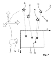
- FIG. 7 shows a schematic illustration for elucidating an angle measuring unit according to the invention
- FIG. 8 shows a schematic illustration for elucidating a further angle measuring unit according to the invention
- FIG. 9 shows a schematic illustration of a recorded sequence of images for elucidating the angle measuring unit according to FIG. 8 .
- FIG. 10 shows an illustration for elucidating the geometrical relationships when using the angle measuring unit in accordance with FIGS. 8 and 9 .
- FIG. 11 shows a basic illustration of the calculation of a best-fit area when using the angle measuring unit in accordance with FIGS. 8 to 10 ,
- FIG. 12 shows a basic illustration of a recorded image of a measurement object for elucidating the functional principle of a further angle measuring unit according to the invention.
- FIG. 13 shows a basic illustration of the calculation of vanishing points in a variant according to the invention of the determination of the emission angle.
- FIGS. 1 to 4 are described jointly below.
- FIGS. 1 and 2 show, in three-dimensional perspective views, a device for non-contact temperature measurement, this device being designated as a whole by 1.
- a thermal imaging camera is shown for elucidating the principle of the invention; in further exemplary embodiments, the device is implemented as a pyrometer.
- the device according to the invention in both cases is advantageously implemented as a handheld device in order to enable very simple handling.
- the device 1 comprises a detector 2 in its interior, which detector can detect IR radiation from a measurement object 3 in a manner known per se.
- the detector 2 is arranged behind an IR optical unit 4 , through which the IR radiation enters the interior of the device 1 .
- the device 1 is thus designed in a manner known per se such that a temperature measurement method can be performed, in which IR radiation from a measurement object 3 is detected by the detector 2 of the device 1 for non-contact temperature measurement.
- the device 1 comprises an angle measuring unit 5 , which is illustrated schematically in greater detail in FIG. 3 for elucidating the principle according to the invention.
- An emission angle 6 formed between the surface normal 7 and the recording direction 8 can be measured by means of the angle measuring unit 5 .
- the recording direction 8 is that direction in which the detector 2 of the device 1 lies, as seen from the currently detected measurement region 9 on the surface of the measurement object 3 .
- the recording direction 8 is thus given by the IR-optical axis of the device 1 . If a plurality of measurement regions 9 are examined simultaneously, then the recording direction 8 arises for each measurement region 9 from the line connecting the measurement region 9 to the device 1 , more precisely to the detector 2 thereof. For large imaging distances, this connecting line is, to a better and better approximation, parallel to the IR-optical axis of the device 1 .
- the emission angle 6 is then measured by virtue of the fact that the distances from the device 1 or the detector 2 to three points 10 spaced apart from one another can be measured and are measured.
- a solid angle but rather only an angle related to a plane. This can be, for example, a horizontal or vertical inclination angle of the surface given by the region 9 in relation to the IR-optical axis of the device 1 . This is already sufficient for many applications.
- the distance measurement is carried out by means of a time-of-flight or phase measurement.
- the measurement beams can be laser beams or ultrasonic waves or the like. Preference is given to using such measurement beams which allow a distance measurement which can be localized as well as possible.
- the measurement beams are generated in a measurement beam generator 12 in the angle measuring unit 5 .
- a beam deflector can also be provided, by means of which the measurement beams are generated temporally successively by the measurement beam generator 12 .
- the measurement region 9 is scanned by a measurement beam in the manner of a scanner.
- a plurality of measurement beam generators 12 spaced apart from one another can be provided, such that each measurement beam is generated by a separate measurement beam generator 12 .
- the distance measurements can be carried out simultaneously.
- the measurement beams are spaced apart from one another at least at the points 10 at which they impinge on the measurement region 9 of the measurement object 3 .
- the distances to the points 10 are then measured by means of the measurement beams in a manner known per se.
- the inclination of the measurement region 9 in relation to the viewing direction of the IR optical unit that is to say the IR-optical axis of the device 1 , can subsequently be deduced.
- the emission angle 6 is calculated therefrom by means of known geometrical equations.
- an evaluation unit 13 is furthermore designed and implemented, by means of which an optical or acoustic warning signal can be generated.
- the evaluation unit 13 is designed such that the warning signal is generated if the emission angle 6 measured by the angle measuring unit 5 leaves a predefined range.
- the evaluation unit 13 is designed such that the warning signal is generated if the emission angle 6 is greater than 60°. In this case, the surface of the measurement region 9 sees so obliquely with respect to the recording direction 8 that a reliable temperature measurement is no longer ensured.
- the warning signal can already be generated if the emission angle exceeds 45° or 30°, or other predefined ranges can be designed.
- the radiant intensity which is incident from the measurement region 9 on the detector 2 decreases.
- the radiant intensity is proportional to the cosine of the emission angle 6 .
- the proportionality factor is composed multiplicatively of the constant luminance of the area and the surface area of the detected measurement region 9 .
- the evaluation unit 13 is designed by means of corresponding programming such that the attenuation of the IR radiation detected by the detector 2 , said attenuation resulting on account of the non-vanishing emission angle 6 , can be corrected and is corrected.
- Lambert's cosine law for the radiant intensity is taken into account by the measured emission angle 6 being correspondingly inserted into the equation mentioned.
- the correction accordingly provides for calculating from the detected measurement result a corrected measurement result which would arise in the case of an optimum, for example vanishing, emission angle 6 .
- the device 1 is implemented as a thermal imaging camera, then the measurement result is present as a two-dimensional arrangement of IR measurement values in the form of a thermal image. By contrast, if the device 1 is a pyrometer, then the measurement result is present as an individual IR measurement value.
- the evaluation unit 13 correspondingly corrects the IR measurement values of the device 1 .
- the corrected IR measurement values are then output as a corrected measurement result.
- the exemplary embodiment described represents a thermal imaging camera.
- This camera is designed, in a manner known per se, for filling pixels of a pixel arrangement with the measured IR measurement values, wherein the pixel arrangement is defined by the detector 2 .
- the detector 2 can be implemented as an FPA or in a scanner arrangement.
- the emission angles 6 for different measurement regions 9 assigned to different pixels or groups of pixels in the recording situation can be measured and are measured successively or simultaneously by means of the angle measuring unit 5 .
- the angle measuring unit 5 is designed such that said location-dependent emission angle 6 can be determined and is determined by means of corresponding distance measurements or by means of the detection and evaluation of a pattern projected onto the object. A pixel-by-pixel correction of the measurement result is then calculated with this location-dependent emission angle.
- the output unit 14 is provided for outputting and/or for providing the calculated emission angle 6 .
- FIG. 5 and FIG. 6 show the automatic, that is to say computer-implemented, calculation of the emission angle from a position of the position (pose) of the measurement object 3 in a three-dimensional space, said position (pose) being related to a recording position and/or recording direction of the device 1 .
- Component parts which are implemented functionally or structurally identically or similarly to the previous exemplary embodiments are designated by the same reference signs and not described separately. The explanations above are thus correspondingly applicable here.
- the distance information items (distances) r 1 , r 2 and r 3 between the recording device 16 or generally the angle measuring unit 5 and the points 10 , which are individually designated by P 1 , P 2 and P 3 , are known as a result of distance measurement.
- the recording device 16 comprises the detector 2 ; in further exemplary embodiments, the detector 2 is embodied separately.
- the angle measuring unit 5 calculates the coordinates of the points P 1 , P 2 and P 3 from the distance information items r 1 , r 2 , r 3 with recourse to the angle values mentioned.
- the angle measuring unit 5 thus calculates the vectors u and v automatically in accordance with this formula.
- the emission angle ⁇ results from the scalar product of the vector n with the vector m describing the recording direction 8 (cf. FIG. 6 ):
- the emission angle ⁇ can be specified in degrees, radians or some other suitable unit system.
- the angle measuring unit 5 thus automatically calculates the emission angle 6 , ⁇ (cf. FIG. 4 ).
- FIG. 7 shows an alternative for determining the position of the measurement object 3 in a three-dimensional space without direct distance measurement.
- a two-dimensional image 17 from the measurement object 3 is recorded in the visible spectral range and/or in the infrared spectral range by means of a recording device 16 .
- the image 17 contains a geometrical shape 18 representing a projection of significant points 10 of the measurement object 3 .
- these points 10 may be distinguished by the measurement object 3 itself, for example by the contour thereof, or by a pattern projection.
- the angle measuring unit 5 can have a pattern projector 37 .
- An associated geometrical comparison shape 19 is stored in the angle measuring unit 5 , with this comparison shape reproducing the actual shape of the measurement object 3 or of a pattern projected onto the measurement object 3 without distortion.
- the details of the geometrical shape 18 are associated with the points 10 of the comparison shape 19 . This gives rise to a system of equations describing—for an unknown position or camera pose of the comparison shape 19 in the three-dimensional space—the projection of the comparison shape 19 onto the image 17 during the imaging process.
- This system of equations is set up according to the pinhole camera model, for example.
- Lenses present in the beam path can be taken into account in a simple manner by the use of a modified and/or adaptive, for example calibrated, pinhole camera model that simulates the imaging properties of the lens system.
- This system of equations is then solved by the angle measuring unit 5 with respect to the coordinates P 1 , P 2 , etc. of the points 10 .
- the angle measuring unit 5 subsequently calculates—as described with regard to FIG. 5 and FIG. 6 —the emission angle ⁇ .
- FIG. 8 to serve for elucidating a further exemplary embodiment of the invention.
- Component parts implemented functionally or structurally identically or similarly to the pervious exemplary embodiments are designated by the same reference signs and not described separately. The explanations above are thus correspondingly applicable here.
- a device 1 according to the invention additionally has a measurement beam generator 12 , which can generate a measurement beam.
- the measurement beam generator 12 is a laser beam generator.
- the measurement beam generator 12 is designed for distance measurement in a manner known per se, for example by means of a time-of-flight measurement and/or a phase measurement of a modulation of the measurement beam.
- the measurement beam generator 12 is coupled to the recording device 16 in such a way that a distance information item measured by means of the measurement beam generator 12 is assigned to each recorded image 17 , 20 .
- This distance information item in this case describes the distance between the recording device 16 and the measurement object 3 , more precisely a partial region 21 on the measurement object at which the measurement beam impinges.
- the recording device 16 with the device 1 is pivoted in front of the measurement object 3 in such a way that the above-mentioned impingement point of the measurement beam describes a desired line 22 on the measurement object 3 .
- the sequence 23 of images 17 , 20 is recorded during this pivoting process.
- Each image 17 , 20 corresponds to a different recording direction 8 , for which reason the image contents 25 , 26 of the images 17 , 20 are arranged in a manner offset with respect to one another.
- the angle measuring unit 5 calculates the motion vectors 24 describing the displacement of the image contents between the images 17 , 20 .
- a motion vector field is present as a result, said motion vector field assigning a motion vector 24 to the significant partial regions 21 or even to all the pixels of the images 17 , 20 .
- This calculation is implemented in a manner known per se by the calculation of an optical flow, a thin optical flow (calculation only for parts of interest of the images 17 , 20 , for example for particularly high-contrast or otherwise suitable image constituents, such as corners, which are distinguished by strong x-gradients and strong y-gradients), according to the KLT tracking method (using KLT features) or in some other suitable way. If the movement between the images 17 , 20 is too large, the motion vectors 24 can be calculated for images with reduced resolution in a resolution pyramid.
- the sequence 23 has only two images 17 , 20 by way of example for explaining the invention. In actual fact, a larger number of images are processed.
- the image 17 is used as a reference image, for example, to which the motion vectors 24 of the images 20 of the sequence 23 are related.
- FIG. 10 shows the reconstruction of the three-dimensional image, that is to say of an image with depth information, of the measurement object 3 with the distance information items from the measurement beam generator 12 .
- the measurement beam forms an angle ⁇ in relation to the recording direction 8 .
- the distance information item allocated to the image 17 is then assigned the impingement point x 1 of the measurement beam.
- the angle measuring unit 5 determines the impingement point x 2 of the measurement beam 27 in the recording position during the recording of the image 20 , relative to the reference image 17 .
- the reference sign 27 designates the measurement beam in the reference system of the reference image 17 .
- the measurement beam 27 forms an angle ⁇ with the recording direction 8 of the reference image 17 .
- the distance information item of the image 20 can be assigned to the impingement point x 2 .
- the angle measuring unit 5 creates a three-dimensional image of the measured points 10 of the measurement object 3 as a point cloud 36 in a three-dimensional space.
- FIG. 11 shows the result as a two-dimensional representation, in which the depth information was suppressed, for the sake of simplicity.
- the angle measuring unit 5 places at least one best-fit area 28 , illustrated here as a best-fit area, through the reconstructed points 10 .
- This best-fit area 28 describes a surface of the measurement object 3 to a very good approximation.
- the angle measuring unit 5 determines the emission angle ⁇ analogously to FIGS. 5 and 6 .
- the method just described with regard to FIGS. 8 to 11 is used to create a three-dimensional image.
- a calculation of an emission angle 6 can be omitted here.
- an actual surface area of a structure of the measurement object 3 can be calculated from the three-dimensional image.
- the measurement object 3 can be a house wall 29 having windows 30 and/or doors 31 .
- the surface area of the windows 30 , of the doors 31 and/or of the house wall can be determined automatically, for example in order to relate a radiation magnitude to the respectively emitting area.
- a plane can often be used as a best-fit area 28 since house walls 29 , windows 30 and/or doors 31 are often implemented in a planar fashion.
- FIGS. 12 and 13 show a further exemplary embodiment of a method according to the invention which can be performed with an angle measuring unit 5 of a device 1 according to the invention.
- Component parts implemented functionally or structurally identically or similarly to the previous exemplary embodiments are designated by the same reference signs and not described separately. The explanations above are thus correspondingly applicable here.
- FIG. 12 shows a measurement object 3 .
- the measurement object 3 has two groups of lines 32 , 33 parallel to one another. As a result of the perspective illustration, the lines 32 appear to run toward a common vanishing point. Likewise, the lines 33 appear to run toward a vanishing point.
- the angle measuring unit 15 creates an image 17 from the measurement object 3 .
- the angle measuring unit 15 has a recording device 16 implemented for recording in an infrared and/or visible spectral range. Recording devices that are sensitive in a further spectral range can also be used.
- the recorded image 17 is shown schematically in FIG. 13 .
- the lines 32 , 33 in the image 17 are identified in a second step.
- the angle measuring unit 15 determines a vanishing point for each line pair of the lines 32 , 33 .
- the angle measuring unit 15 calculates two vanishing points 34 , 35 for the example illustrated. Vanishing point 34 is described by the lines 32 , and vanishing point 35 by the lines 33 .
- the angle measuring unit 5 calculates for each vanishing point 34 , 35 , with the aid of a stored imaging geometry or in some other way, at what angle in relation to a recording direction 8 said vanishing point 34 , 35 appears in the scene in which the measurement object 3 is situated. Subsequently or simultaneously, the angle measuring unit 5 determines, with the aid of the stored imaging geometry or in some other way, at what angle in relation to a recording direction 8 a selected point 10 on a line 32 , 33 , for example the point P 1 , appears in the scene containing the measurement object 3 .
- the angle formed by the direction in which the selected point 10 (P 1 ) lies and the direction of the vanishing point 32 or 33 is equal to the angle formed by the direction in which the selected point 10 (P 1 ) lies and the considered line 32 or 33 .
- the emission angle 6 can thus be calculated with simple sums of internal angles.
- the angle measuring unit 5 thus calculates the sought emission angle 6 , ⁇ .
- a more precise determination of the emission angle 6 is performed using the method from Ko ⁇ hacek over (s) ⁇ ecka, Jana; Zhang, Wie: Video Compass, European Conference on Computer Vision 2002, LNCS 2350, Springer Verlag, Springer: Berlin etc., 2006, pp. 476-491.
- the calculation steps presented therein are part of this exemplary embodiment.
- the calculated emission angle is provided for further processing at the output unit 14 .
- an angle measuring unit 5 such that an emission angle 6 of the IR radiation detected by a detector 2 for temperature measurement can be measured on the measurement region 9 of a measurement object 3 which emits the IR radiation.
Landscapes
- Physics & Mathematics (AREA)
- General Physics & Mathematics (AREA)
- Spectroscopy & Molecular Physics (AREA)
- Radiation Pyrometers (AREA)
Applications Claiming Priority (4)
| Application Number | Priority Date | Filing Date | Title |
|---|---|---|---|
| DE201210003255 DE102012003255B8 (de) | 2012-02-21 | 2012-02-21 | Vorrichtung zur berührungslosen Temperaturmessung und Temperaturmessverfahren |
| DE102012003255.2 | 2012-02-21 | ||
| DE102012003255 | 2012-02-21 | ||
| PCT/EP2013/000484 WO2013124056A1 (fr) | 2012-02-21 | 2013-02-20 | Dispositif de mesure thermique sans contact et procédé de mesure thermique |
Publications (2)
| Publication Number | Publication Date |
|---|---|
| US20150110152A1 US20150110152A1 (en) | 2015-04-23 |
| US9857232B2 true US9857232B2 (en) | 2018-01-02 |
Family
ID=47780012
Family Applications (1)
| Application Number | Title | Priority Date | Filing Date |
|---|---|---|---|
| US14/380,117 Active 2035-04-03 US9857232B2 (en) | 2012-02-21 | 2013-02-20 | Device for non-contact temperature measurement and temperature measurement method |
Country Status (4)
| Country | Link |
|---|---|
| US (1) | US9857232B2 (fr) |
| CN (1) | CN204346588U (fr) |
| DE (1) | DE102012003255B8 (fr) |
| WO (1) | WO2013124056A1 (fr) |
Cited By (2)
| Publication number | Priority date | Publication date | Assignee | Title |
|---|---|---|---|---|
| TWI880722B (zh) * | 2023-05-08 | 2025-04-11 | 美商賀利氏科納米北美有限責任公司 | 自動化高溫計追蹤 |
| WO2025219373A1 (fr) * | 2024-04-19 | 2025-10-23 | Universite de Bordeaux | Dispositif portatif de détection d'un faisceau laser, dispositif de visualisation et procédé associé |
Families Citing this family (10)
| Publication number | Priority date | Publication date | Assignee | Title |
|---|---|---|---|---|
| EP2634747A1 (fr) * | 2012-02-29 | 2013-09-04 | Flir Systems AB | Procédé et système de projection d'une représentation visible d'un rayonnement infrarouge |
| DE102015102557B4 (de) * | 2015-02-23 | 2023-02-02 | Fraunhofer-Gesellschaft zur Förderung der angewandten Forschung e.V. | Sichtsystem |
| CN107543616B (zh) * | 2016-06-24 | 2019-08-20 | 丘国强 | 利用三维热成像的机器状况监测系统 |
| DE102016218291A1 (de) | 2016-09-23 | 2018-03-29 | Robert Bosch Gmbh | Verfahren zur kontaktfreien Ermittlung einer zweidimensionalen Temperaturin-formation sowie Infrarot-Messsystem |
| CN108111801B (zh) * | 2016-11-23 | 2020-02-21 | 武汉通畅汽车电子照明有限公司 | Adas视觉处理系统的耐温试验系统及方法 |
| DE102017107336A1 (de) * | 2017-04-05 | 2018-10-11 | Testo SE & Co. KGaA | Messgerät und korrespondierendes Messverfahren |
| JP6931548B2 (ja) * | 2017-04-14 | 2021-09-08 | 株式会社Uacj | 情報処理装置、温度測定システム、情報処理装置の制御方法、および制御プログラム |
| TWI704502B (zh) * | 2018-06-08 | 2020-09-11 | 晟風科技股份有限公司 | 具有對距離做溫度補償功能之熱像儀及其溫度補償方法 |
| CN111707377B (zh) * | 2020-06-29 | 2021-05-18 | 安徽必海微软件科技有限公司 | 一种体温检测云平台系统 |
| DE102022108152A1 (de) * | 2022-04-05 | 2023-10-05 | Testo SE & Co. KGaA | Verfahren und Vorrichtung zur berührungslosen Messung einer Temperatur |
Citations (29)
| Publication number | Priority date | Publication date | Assignee | Title |
|---|---|---|---|---|
| US4498765A (en) * | 1981-06-25 | 1985-02-12 | Universite Paris X - Paris | Processes for the remote measurement of the emissivity and/or the true temperature of a body with relatively smooth surface |
| US5003166A (en) | 1989-11-07 | 1991-03-26 | Massachusetts Institute Of Technology | Multidimensional range mapping with pattern projection and cross correlation |
| US5008543A (en) * | 1989-01-18 | 1991-04-16 | Sat(Societe Anonyme De Telecommunications | System for determining the position of at least one target by triangulation |
| US5011295A (en) * | 1989-10-17 | 1991-04-30 | Houston Advanced Research Center | Method and apparatus to simultaneously measure emissivities and thermodynamic temperatures of remote objects |
| US5436443A (en) * | 1994-07-06 | 1995-07-25 | The United States Of America As Represented By The Administrator Of The National Aeronautics And Space Administration | Polaradiometric pyrometer in which the parallel and perpendicular components of radiation reflected from an unpolarized light source are equalized with the thermal radiation emitted from a measured object to determine its true temperature |
| US6115128A (en) | 1997-09-17 | 2000-09-05 | The Regents Of The Univerity Of California | Multi-dimensional position sensor using range detectors |
| EP1033556A1 (fr) | 1998-09-21 | 2000-09-06 | Kabushiki Kaisha TOPCON | Procede de mesure tridimensionnelle et instrument d'etude l'utilisant |
| US20020080357A1 (en) * | 2000-11-15 | 2002-06-27 | Dana Kristin J. | Apparatus and method for measuring spatially varying bidirectional reflectance distribution function |
| DE10133761A1 (de) | 2001-07-11 | 2003-01-30 | Vitronic Dr Ing Stein Bildvera | Verfahren und Vorrichtung zur virtuellen Lagebestimmung eines Fahrzeugaufbaus |
| US20050190285A1 (en) * | 1999-12-08 | 2005-09-01 | Yujiro Ito | Auto-focus apparatus, focus adjusting method, image capturing apparatus and image capturing method |
| US6950546B2 (en) * | 2002-12-03 | 2005-09-27 | Og Technologies, Inc. | Apparatus and method for detecting surface defects on a workpiece such as a rolled/drawn metal bar |
| EP1582846A2 (fr) | 2004-03-31 | 2005-10-05 | Mitutoyo Corporation | Échelle pour un système de mesure de translation et d'orientation |
| DE102004027341A1 (de) | 2004-05-27 | 2005-12-22 | Deutsches Zentrum für Luft- und Raumfahrt e.V. | Verfahren und Vorrichtung für ein optoelektronisches Positions- und Lagemesssystem |
| US20060000812A1 (en) * | 2004-07-02 | 2006-01-05 | Jan Weber | Method and apparatus for controlling and adjusting the intensity profile of a laser beam employed in a laser welder for welding polymeric and metallic components |
| US20080174702A1 (en) * | 2007-01-23 | 2008-07-24 | Pixart Imaging Inc. | Quasi analog knob control method and appartus using the same |
| US20090218478A1 (en) * | 2005-04-23 | 2009-09-03 | Lg Electronics Inc. | Position detection device for mobile robot and robot cleaner including the same |
| US20100014555A1 (en) * | 2005-09-01 | 2010-01-21 | Michael Twerdochlib | Method of measuring in situ differential emissivity and temperature |
| US20100131225A1 (en) | 2008-11-26 | 2010-05-27 | Fluke Corporation | System and method for detecting thermographic anomalies |
| US7744274B1 (en) * | 2007-06-20 | 2010-06-29 | Ultratech, Inc. | Methods and apparatus for temperature measurement and control on a remote substrate surface |
| US20100292950A1 (en) * | 2007-12-20 | 2010-11-18 | Toyo University | Radiation thermometry and radiation thermometry system |
| WO2011075124A1 (fr) | 2009-12-16 | 2011-06-23 | Hewlett-Packard Development Company, L.P. | Estimation d'une structure 3d à partir d'une image 2d |
| US20110311104A1 (en) | 2010-06-17 | 2011-12-22 | Microsoft Corporation | Multi-Stage Linear Structure from Motion |
| US20120155509A1 (en) * | 2009-08-28 | 2012-06-21 | Juntaro Ishii | Electrode member, electron energy analyzer, photoelectron energy analyzer, and temperature measuring apparatus |
| US8306308B2 (en) * | 2007-08-28 | 2012-11-06 | Posco | Method for optically detecting surface defect of round wire rod |
| US8696197B2 (en) * | 2005-07-05 | 2014-04-15 | Mattson Technology, Inc. | Method and system for determining optical properties of semiconductor wafers |
| US20150115178A1 (en) * | 2010-02-12 | 2015-04-30 | Vantage Surgical Systems, Inc. | Methods and systems for guiding an emission to a target |
| US20160157732A1 (en) * | 2013-08-07 | 2016-06-09 | Bio Echo Net Inc. | Infrared thermometer |
| US9516243B2 (en) * | 2011-07-20 | 2016-12-06 | Siemens Aktiengesellschaft | Method and system for emissivity determination |
| US20170074848A1 (en) * | 2015-09-14 | 2017-03-16 | Robert Bosch Gmbh | Food packaging arrangement |
Family Cites Families (4)
| Publication number | Priority date | Publication date | Assignee | Title |
|---|---|---|---|---|
| ATE248356T1 (de) * | 1998-01-30 | 2003-09-15 | Tecnimed Srl | Infrarot thermometer |
| DE19950849B4 (de) * | 1999-10-21 | 2004-09-16 | Fraunhofer-Gesellschaft zur Förderung der angewandten Forschung e.V. | Vorrichtung sowie Verfahren zur Detektion, Entfernungs-, Größen- und Temperaturmessung von einer Wärmequelle |
| DE10335319A1 (de) * | 2003-08-01 | 2005-02-24 | Siemens Ag | Elektrisches Gerät mit Strahlungssensor |
| US7611278B2 (en) * | 2003-12-02 | 2009-11-03 | White Box, Inc. | Infrared thermometers |
-
2012
- 2012-02-21 DE DE201210003255 patent/DE102012003255B8/de active Active
-
2013
- 2013-02-20 WO PCT/EP2013/000484 patent/WO2013124056A1/fr not_active Ceased
- 2013-02-20 CN CN201390000392.0U patent/CN204346588U/zh not_active Expired - Lifetime
- 2013-02-20 US US14/380,117 patent/US9857232B2/en active Active
Patent Citations (31)
| Publication number | Priority date | Publication date | Assignee | Title |
|---|---|---|---|---|
| US4498765A (en) * | 1981-06-25 | 1985-02-12 | Universite Paris X - Paris | Processes for the remote measurement of the emissivity and/or the true temperature of a body with relatively smooth surface |
| US5008543A (en) * | 1989-01-18 | 1991-04-16 | Sat(Societe Anonyme De Telecommunications | System for determining the position of at least one target by triangulation |
| US5011295A (en) * | 1989-10-17 | 1991-04-30 | Houston Advanced Research Center | Method and apparatus to simultaneously measure emissivities and thermodynamic temperatures of remote objects |
| US5003166A (en) | 1989-11-07 | 1991-03-26 | Massachusetts Institute Of Technology | Multidimensional range mapping with pattern projection and cross correlation |
| US5436443A (en) * | 1994-07-06 | 1995-07-25 | The United States Of America As Represented By The Administrator Of The National Aeronautics And Space Administration | Polaradiometric pyrometer in which the parallel and perpendicular components of radiation reflected from an unpolarized light source are equalized with the thermal radiation emitted from a measured object to determine its true temperature |
| US6115128A (en) | 1997-09-17 | 2000-09-05 | The Regents Of The Univerity Of California | Multi-dimensional position sensor using range detectors |
| EP1033556A1 (fr) | 1998-09-21 | 2000-09-06 | Kabushiki Kaisha TOPCON | Procede de mesure tridimensionnelle et instrument d'etude l'utilisant |
| US20050190285A1 (en) * | 1999-12-08 | 2005-09-01 | Yujiro Ito | Auto-focus apparatus, focus adjusting method, image capturing apparatus and image capturing method |
| US20020080357A1 (en) * | 2000-11-15 | 2002-06-27 | Dana Kristin J. | Apparatus and method for measuring spatially varying bidirectional reflectance distribution function |
| DE10133761A1 (de) | 2001-07-11 | 2003-01-30 | Vitronic Dr Ing Stein Bildvera | Verfahren und Vorrichtung zur virtuellen Lagebestimmung eines Fahrzeugaufbaus |
| US6950546B2 (en) * | 2002-12-03 | 2005-09-27 | Og Technologies, Inc. | Apparatus and method for detecting surface defects on a workpiece such as a rolled/drawn metal bar |
| EP1582846A2 (fr) | 2004-03-31 | 2005-10-05 | Mitutoyo Corporation | Échelle pour un système de mesure de translation et d'orientation |
| DE102004027341A1 (de) | 2004-05-27 | 2005-12-22 | Deutsches Zentrum für Luft- und Raumfahrt e.V. | Verfahren und Vorrichtung für ein optoelektronisches Positions- und Lagemesssystem |
| US20060000812A1 (en) * | 2004-07-02 | 2006-01-05 | Jan Weber | Method and apparatus for controlling and adjusting the intensity profile of a laser beam employed in a laser welder for welding polymeric and metallic components |
| US20090218478A1 (en) * | 2005-04-23 | 2009-09-03 | Lg Electronics Inc. | Position detection device for mobile robot and robot cleaner including the same |
| US8696197B2 (en) * | 2005-07-05 | 2014-04-15 | Mattson Technology, Inc. | Method and system for determining optical properties of semiconductor wafers |
| US20100014555A1 (en) * | 2005-09-01 | 2010-01-21 | Michael Twerdochlib | Method of measuring in situ differential emissivity and temperature |
| US20080174702A1 (en) * | 2007-01-23 | 2008-07-24 | Pixart Imaging Inc. | Quasi analog knob control method and appartus using the same |
| US7744274B1 (en) * | 2007-06-20 | 2010-06-29 | Ultratech, Inc. | Methods and apparatus for temperature measurement and control on a remote substrate surface |
| US8306308B2 (en) * | 2007-08-28 | 2012-11-06 | Posco | Method for optically detecting surface defect of round wire rod |
| US20100292950A1 (en) * | 2007-12-20 | 2010-11-18 | Toyo University | Radiation thermometry and radiation thermometry system |
| US8498836B2 (en) * | 2008-11-26 | 2013-07-30 | Fluke Corporation | System and method for detecting thermographic anomalies |
| US20100131225A1 (en) | 2008-11-26 | 2010-05-27 | Fluke Corporation | System and method for detecting thermographic anomalies |
| US8944679B2 (en) * | 2009-08-28 | 2015-02-03 | National Institute Of Advanced Industrial Science And Technology | Electrode member, electron energy analyzer, photoelectron energy analyzer, and temperature measuring apparatus |
| US20120155509A1 (en) * | 2009-08-28 | 2012-06-21 | Juntaro Ishii | Electrode member, electron energy analyzer, photoelectron energy analyzer, and temperature measuring apparatus |
| WO2011075124A1 (fr) | 2009-12-16 | 2011-06-23 | Hewlett-Packard Development Company, L.P. | Estimation d'une structure 3d à partir d'une image 2d |
| US20150115178A1 (en) * | 2010-02-12 | 2015-04-30 | Vantage Surgical Systems, Inc. | Methods and systems for guiding an emission to a target |
| US20110311104A1 (en) | 2010-06-17 | 2011-12-22 | Microsoft Corporation | Multi-Stage Linear Structure from Motion |
| US9516243B2 (en) * | 2011-07-20 | 2016-12-06 | Siemens Aktiengesellschaft | Method and system for emissivity determination |
| US20160157732A1 (en) * | 2013-08-07 | 2016-06-09 | Bio Echo Net Inc. | Infrared thermometer |
| US20170074848A1 (en) * | 2015-09-14 | 2017-03-16 | Robert Bosch Gmbh | Food packaging arrangement |
Non-Patent Citations (1)
| Title |
|---|
| Tasi, Yi-Min, et al., "Block-Based Vanishing Line and Vanishing Point Detection for 3D Scene Reconstruction", Intelligent Signal Processing and Communications, 2006, ISPACS International Syumposium on, IEEE, PI, Dec. 1, 2006, pp. 586-589. |
Cited By (3)
| Publication number | Priority date | Publication date | Assignee | Title |
|---|---|---|---|---|
| TWI880722B (zh) * | 2023-05-08 | 2025-04-11 | 美商賀利氏科納米北美有限責任公司 | 自動化高溫計追蹤 |
| WO2025219373A1 (fr) * | 2024-04-19 | 2025-10-23 | Universite de Bordeaux | Dispositif portatif de détection d'un faisceau laser, dispositif de visualisation et procédé associé |
| FR3161476A1 (fr) * | 2024-04-19 | 2025-10-24 | Universite de Bordeaux | Dispositif portatif de détection d’un faisceau laser, dispositif de visualisation et procédé associé |
Also Published As
| Publication number | Publication date |
|---|---|
| DE102012003255A1 (de) | 2013-08-22 |
| DE102012003255B8 (de) | 2014-01-16 |
| CN204346588U (zh) | 2015-05-20 |
| WO2013124056A1 (fr) | 2013-08-29 |
| DE102012003255B4 (de) | 2013-10-10 |
| US20150110152A1 (en) | 2015-04-23 |
Similar Documents
| Publication | Publication Date | Title |
|---|---|---|
| US9857232B2 (en) | Device for non-contact temperature measurement and temperature measurement method | |
| EP3491332B1 (fr) | Estimation d'une carte de réflectivité à partir de systèmes de lumière structurée basée sur des points | |
| US9762883B2 (en) | Balancing colors in a scanned three-dimensional image | |
| US7616817B2 (en) | Three dimensional shape correlator | |
| US7075661B2 (en) | Apparatus and method for obtaining three-dimensional positional data from a two-dimensional captured image | |
| US4635203A (en) | Passive range measurement apparatus and method | |
| EP3236286A1 (fr) | Procédé et système de mise en service automatique | |
| US20110007948A1 (en) | System and method for automatic stereo measurement of a point of interest in a scene | |
| CN109961468A (zh) | 基于双目视觉的体积测量方法、装置及存储介质 | |
| US10732284B2 (en) | Live metrology of an object during manufacturing or other operations | |
| Gliß et al. | Improved optical flow velocity analysis in SO 2 camera images of volcanic plumes–implications for emission-rate retrievals investigated at Mt Etna, Italy and Guallatiri, Chile | |
| US20200007843A1 (en) | Spatiotemporal calibration of rgb-d and displacement sensors | |
| CN111025032B (zh) | 一种基于升空平台的天线波束测量系统及方法 | |
| Crispel et al. | All-sky photogrammetry techniques to georeference a cloud field | |
| KR20130121290A (ko) | 회전식 라인 카메라로 획득한 실내 전방위 영상의 지오레퍼런싱 방법 | |
| Holmgren et al. | Estimation of tree position and stem diameter using simultaneous localization and mapping with data from a backpack-mounted laser scanner | |
| Frangez et al. | Assessment and improvement of distance measurement accuracy for time-of-flight cameras | |
| Fuchs | Calibration and multipath mitigation for increased accuracy of time-of-flight camera measurements in robotic applications | |
| Fuersattel et al. | Accurate laser scanner to camera calibration with application to range sensor evaluation | |
| Alaniz-Plata et al. | Extrinsic calibration of complex machine vision system for mobile robot | |
| US20240114119A1 (en) | Image processing device, image processing method, and program | |
| Langmann | Wide area 2D/3D imaging: development, analysis and applications | |
| Vaida et al. | Automatic extrinsic calibration of LiDAR and monocular camera images | |
| Lavieri et al. | Image-based measurement system for regular waves in an offshore basin | |
| Huang et al. | Extrinsic calibration of a multi-beam LiDAR system with improved intrinsic laser parameters using v-shaped planes and infrared images |
Legal Events
| Date | Code | Title | Description |
|---|---|---|---|
| AS | Assignment |
Owner name: TESTO AG, GERMANY Free format text: ASSIGNMENT OF ASSIGNORS INTEREST;ASSIGNORS:RENTMEISTER, SARA;EVERS-SENNE, JAN-FRISO;SIGNING DATES FROM 20140819 TO 20140821;REEL/FRAME:034359/0652 |
|
| STCF | Information on status: patent grant |
Free format text: PATENTED CASE |
|
| MAFP | Maintenance fee payment |
Free format text: PAYMENT OF MAINTENANCE FEE, 4TH YEAR, LARGE ENTITY (ORIGINAL EVENT CODE: M1551); ENTITY STATUS OF PATENT OWNER: LARGE ENTITY Year of fee payment: 4 |
|
| MAFP | Maintenance fee payment |
Free format text: PAYMENT OF MAINTENANCE FEE, 8TH YEAR, LARGE ENTITY (ORIGINAL EVENT CODE: M1552); ENTITY STATUS OF PATENT OWNER: LARGE ENTITY Year of fee payment: 8 |