US9860505B2 - Transmitting device, transmitting method, receiving device, and receiving method - Google Patents
Transmitting device, transmitting method, receiving device, and receiving method Download PDFInfo
- Publication number
- US9860505B2 US9860505B2 US14/784,353 US201414784353A US9860505B2 US 9860505 B2 US9860505 B2 US 9860505B2 US 201414784353 A US201414784353 A US 201414784353A US 9860505 B2 US9860505 B2 US 9860505B2
- Authority
- US
- United States
- Prior art keywords
- video data
- luminance value
- range
- level
- high luminance
- Prior art date
- Legal status (The legal status is an assumption and is not a legal conclusion. Google has not performed a legal analysis and makes no representation as to the accuracy of the status listed.)
- Active
Links
Images




Classifications
-
- H—ELECTRICITY
- H04—ELECTRIC COMMUNICATION TECHNIQUE
- H04N—PICTORIAL COMMUNICATION, e.g. TELEVISION
- H04N5/00—Details of television systems
- H04N5/38—Transmitter circuitry for the transmission of television signals according to analogue transmission standards
-
- H—ELECTRICITY
- H04—ELECTRIC COMMUNICATION TECHNIQUE
- H04N—PICTORIAL COMMUNICATION, e.g. TELEVISION
- H04N9/00—Details of colour television systems
- H04N9/64—Circuits for processing colour signals
- H04N9/68—Circuits for processing colour signals for controlling the amplitude of colour signals, e.g. automatic chroma control circuits
- H04N9/69—Circuits for processing colour signals for controlling the amplitude of colour signals, e.g. automatic chroma control circuits for modifying the colour signals by gamma correction
-
- H—ELECTRICITY
- H04—ELECTRIC COMMUNICATION TECHNIQUE
- H04N—PICTORIAL COMMUNICATION, e.g. TELEVISION
- H04N19/00—Methods or arrangements for coding, decoding, compressing or decompressing digital video signals
- H04N19/46—Embedding additional information in the video signal during the compression process
-
- H—ELECTRICITY
- H04—ELECTRIC COMMUNICATION TECHNIQUE
- H04N—PICTORIAL COMMUNICATION, e.g. TELEVISION
- H04N19/00—Methods or arrangements for coding, decoding, compressing or decompressing digital video signals
- H04N19/70—Methods or arrangements for coding, decoding, compressing or decompressing digital video signals characterised by syntax aspects related to video coding, e.g. related to compression standards
-
- H—ELECTRICITY
- H04—ELECTRIC COMMUNICATION TECHNIQUE
- H04N—PICTORIAL COMMUNICATION, e.g. TELEVISION
- H04N19/00—Methods or arrangements for coding, decoding, compressing or decompressing digital video signals
- H04N19/85—Methods or arrangements for coding, decoding, compressing or decompressing digital video signals using pre-processing or post-processing specially adapted for video compression
-
- H—ELECTRICITY
- H04—ELECTRIC COMMUNICATION TECHNIQUE
- H04N—PICTORIAL COMMUNICATION, e.g. TELEVISION
- H04N21/00—Selective content distribution, e.g. interactive television or video on demand [VOD]
- H04N21/20—Servers specifically adapted for the distribution of content, e.g. VOD servers; Operations thereof
- H04N21/23—Processing of content or additional data; Elementary server operations; Server middleware
- H04N21/236—Assembling of a multiplex stream, e.g. transport stream, by combining a video stream with other content or additional data, e.g. inserting a URL [Uniform Resource Locator] into a video stream, multiplexing software data into a video stream; Remultiplexing of multiplex streams; Insertion of stuffing bits into the multiplex stream, e.g. to obtain a constant bit-rate; Assembling of a packetised elementary stream
- H04N21/23614—Multiplexing of additional data and video streams
-
- H—ELECTRICITY
- H04—ELECTRIC COMMUNICATION TECHNIQUE
- H04N—PICTORIAL COMMUNICATION, e.g. TELEVISION
- H04N21/00—Selective content distribution, e.g. interactive television or video on demand [VOD]
- H04N21/40—Client devices specifically adapted for the reception of or interaction with content, e.g. set-top-box [STB]; Operations thereof
- H04N21/43—Processing of content or additional data, e.g. demultiplexing additional data from a digital video stream; Elementary client operations, e.g. monitoring of home network or synchronising decoder's clock; Client middleware
- H04N21/431—Generation of visual interfaces for content selection or interaction; Content or additional data rendering
- H04N21/4318—Generation of visual interfaces for content selection or interaction; Content or additional data rendering by altering the content in the rendering process, e.g. blanking, blurring or masking an image region
-
- H—ELECTRICITY
- H04—ELECTRIC COMMUNICATION TECHNIQUE
- H04N—PICTORIAL COMMUNICATION, e.g. TELEVISION
- H04N21/00—Selective content distribution, e.g. interactive television or video on demand [VOD]
- H04N21/40—Client devices specifically adapted for the reception of or interaction with content, e.g. set-top-box [STB]; Operations thereof
- H04N21/43—Processing of content or additional data, e.g. demultiplexing additional data from a digital video stream; Elementary client operations, e.g. monitoring of home network or synchronising decoder's clock; Client middleware
- H04N21/434—Disassembling of a multiplex stream, e.g. demultiplexing audio and video streams, extraction of additional data from a video stream; Remultiplexing of multiplex streams; Extraction or processing of SI; Disassembling of packetised elementary stream
- H04N21/4348—Demultiplexing of additional data and video streams
-
- H—ELECTRICITY
- H04—ELECTRIC COMMUNICATION TECHNIQUE
- H04N—PICTORIAL COMMUNICATION, e.g. TELEVISION
- H04N21/00—Selective content distribution, e.g. interactive television or video on demand [VOD]
- H04N21/80—Generation or processing of content or additional data by content creator independently of the distribution process; Content per se
- H04N21/83—Generation or processing of protective or descriptive data associated with content; Content structuring
- H04N21/84—Generation or processing of descriptive data, e.g. content descriptors
-
- H—ELECTRICITY
- H04—ELECTRIC COMMUNICATION TECHNIQUE
- H04N—PICTORIAL COMMUNICATION, e.g. TELEVISION
- H04N5/00—Details of television systems
- H04N5/14—Picture signal circuitry for video frequency region
- H04N5/20—Circuitry for controlling amplitude response
- H04N5/202—Gamma control
-
- H—ELECTRICITY
- H04—ELECTRIC COMMUNICATION TECHNIQUE
- H04N—PICTORIAL COMMUNICATION, e.g. TELEVISION
- H04N5/00—Details of television systems
- H04N5/44—Receiver circuitry for the reception of television signals according to analogue transmission standards
- H04N5/57—Control of contrast or brightness
-
- H—ELECTRICITY
- H04—ELECTRIC COMMUNICATION TECHNIQUE
- H04N—PICTORIAL COMMUNICATION, e.g. TELEVISION
- H04N7/00—Television systems
- H04N7/08—Systems for the simultaneous or sequential transmission of more than one television signal, e.g. additional information signals, the signals occupying wholly or partially the same frequency band, e.g. by time division
-
- H—ELECTRICITY
- H04—ELECTRIC COMMUNICATION TECHNIQUE
- H04N—PICTORIAL COMMUNICATION, e.g. TELEVISION
- H04N9/00—Details of colour television systems
- H04N9/64—Circuits for processing colour signals
- H04N9/641—Multi-purpose receivers, e.g. for auxiliary information
-
- H—ELECTRICITY
- H04—ELECTRIC COMMUNICATION TECHNIQUE
- H04N—PICTORIAL COMMUNICATION, e.g. TELEVISION
- H04N23/00—Cameras or camera modules comprising electronic image sensors; Control thereof
- H04N23/70—Circuitry for compensating brightness variation in the scene
- H04N23/741—Circuitry for compensating brightness variation in the scene by increasing the dynamic range of the image compared to the dynamic range of the electronic image sensors
-
- H04N5/2355—
Definitions
- the present technology relates to a transmitting device, a transmitting method, a receiving device, and a receiving method, and more particularly to a transmitting device and others for transmitting transmission video data obtained by application of a gamma curve.
- Virtual reality of a high-quality image is improvable by increasing a synchronous reproduction ability for synchronous reproduction of a luminance minimum level and a luminance maximum level at the time of image display.
- This synchronous reproduction ability is sometimes called a display dynamic range.
- a conventional standard has been set to a white luminance value of 100 cd/m2 throughout cases from camera-imaging to monitoring display.
- a conventional transmission has been set to 8-bit transmission (representable gradations: 0 to 255) as a precondition.
- the representable gradations are expandable by the use of 10-bit transmission or larger-bit transmission, for example.
- Gamma correction is further known as a correction of gamma characteristics of a display achieved by input of data having characteristics opposite to the characteristics of the display.
- Non-Patent Document 1 describes transmission of a video stream generated by encoding transmission video data which has been obtained by application of a gamma curve to input video data having levels of 0 to 100%*N (N: larger than 1), for example.
- An object of the present technology is to realize display with an appropriate luminance dynamic range on a receiving side.
- a concept of the present technology is directed to a transmitting device including:
- a processing unit that applies a gamma curve to input video data having a level range from 0% to 100%*N (N: a number larger than 1) to obtain transmission video data;
- a transmission unit that transmits the transmission video data together with auxiliary information used for converting a high-luminance level on a receiving side.
- the processing unit applies a gamma curve to input video data having a level range from 0% to 100%*N (N: a number larger than 1) to obtain transmission video data.
- the transmission unit transmits the transmission video data together with auxiliary information used for converting a high-luminance level on a receiving side.
- the transmission unit may transmit a container in a predetermined format that contains a video stream obtained by encoding the transmission video data.
- An auxiliary information insertion unit that inserts the auxiliary information into a layer of the video stream and/or a layer of the container may be provided.
- the processing unit may further execute a process for converting a level of output video data obtained by applying the gamma curve to the input video data, which level corresponds to a level of the input video data in a range from 100% to 100%*N, into a level corresponding to 100% of the input video data so as to obtain the transmission video data.
- the auxiliary information may contain information on a filter applied to pixel data of the transmission video data at a level corresponding to 100% of the input video data.
- the processing unit may further execute a process for converting a level of output video data obtained by applying the gamma curve to the input video data, which level corresponds to a level of the input video data in a range from a threshold equal to or lower than a level corresponding to 100% to 100%*N, into a level in a range from the threshold to a level corresponding to 100% of the input video data so as to obtain the transmission video data.
- the auxiliary information may contain information on a filter applied to pixel data of the transmission video data in a range from the threshold to a level corresponding to 100% of the input video data.
- the auxiliary information may contain information on a conversion curve applied to pixel data of the transmission video data in a range from the threshold to a level corresponding to 100% of the input video data.
- the processing unit may use output video data as the transmission video data without a change, which output video data is obtained by applying the gamma curve to the input video data.
- the auxiliary information may contain information on a conversion curve applied to a high-level side of the transmission video data.
- the transmission video data obtained by applying the gamma curve to the input video data having the level range from 0% to 100%*N is transmitted together with the auxiliary information used for converting the high-luminance level on the receiving side. Accordingly, the receiving side is capable of converting the high-luminance level of the transmission video data based on the auxiliary information.
- video data with a high dynamic range is obtainable by converting transmission video data with a low dynamic range having a level corresponding to 100% level of the input video data as the maximum level such that the maximum level becomes high.
- video data with a low dynamic range for example, is obtainable by converting transmission video data with a high dynamic range having a level corresponding to 100%*N level of the input video data as the maximum level such that the maximum level becomes low. Accordingly, display with an appropriate luminance dynamic range is realizable on the receiving side.
- an identification information insertion unit may be provided.
- This identification information insertion unit inserts, into the layer of the container, identification information that indicates that the auxiliary information has been inserted into the layer of the video stream.
- the receiving side is capable of recognizing insertion of the auxiliary information into this video stream without the necessity of decoding the video stream, and therefore appropriately extracting the auxiliary information from the video stream.
- Another concept of the present technology is directed to a receiving device including:
- a reception unit that receives transmission video data obtained by applying a gamma curve to input video data having a level range from 0% to 100%*N (N: a number larger than 1);
- a processing unit that converts a high-level side level range of the transmission video data such that a maximum level becomes a predetermined level based on auxiliary information received together with the transmission video data.
- the reception unit receives transmission video data.
- This transmission video data is obtained by applying a gamma curve to input video data having a level range from 0% to 100%*N (N: a number larger than 1).
- the processing unit converts a high-level side level range of the transmission video data such that a maximum level becomes a predetermined level based on auxiliary information received together with the transmission video data.
- the processing unit may determine the predetermined level based on information on the N and information on a luminance dynamic range of a monitor contained in the auxiliary information.
- the reception unit transmits a container in a predetermined format that contains a video stream obtained by encoding the transmission video data.
- the auxiliary information is inserted into a layer of the video stream.
- the transmission video data may be video data obtained by further executing a process for converting a level of output video data obtained by applying the gamma curve to the input video data, which level corresponds to a level of the input video data in a range from 100% to 100%*N, into a level corresponding to 100% of the input video data.
- the processing unit may convert levels of respective pixel data corresponding to 100% of the input video data into levels in a range from a level corresponding to 100% of the input video data to the predetermined level by applying a filter specified in filter information contained in the auxiliary information.
- the transmission video data may be video data obtained by further executing a process for converting a level of output video data obtained by applying the gamma curve to the input video data, which level corresponds to a level of the input video data in a range from a threshold equal to or lower than a level corresponding to 100% to 100%*N, into a level in a range from the threshold to a level corresponding to 100% of the input video data.
- the processing unit may convert levels of respective pixel data in a range from the threshold to a level corresponding to 100% of the input video data into levels in a range from the threshold to the predetermined level by applying a filter specified in filter information contained in the auxiliary information.
- the transmission video data may be video data obtained by further executing a process for converting a level of output video data obtained by applying the gamma curve to the input video data, which level corresponds to a level of the input video data in a range from a threshold equal to or lower than a level corresponding to 100% to 100%*N, into a level in a range from the threshold to a level corresponding to 100% of the input video data.
- the processing unit may convert levels of respective pixel data in a range from the threshold to a level corresponding to 100% of the input video data into levels in a range from the threshold to the predetermined level by applying conversion curve information contained in the auxiliary information.
- output video data may be used as the transmission video data without a change, which output video data is obtained by applying the gamma curve to the input video data.
- the processing unit may convert levels of respective pixel data of the transmission video data in a range from a threshold equal to or lower than a level corresponding 100% of the input video data to a level corresponding to 100%*N of the input video data into levels in a range from the threshold to the predetermined level corresponding to L*100% (L: a number equal to or smaller than N) of the input video data by applying conversion curve information contained in the auxiliary information.
- the transmission video data obtained by applying the gamma curve to input video data having the level range from 0% to 100%*N is received.
- the high-level side level range of this transmission video data is converted such that the maximum level becomes the predetermined level, based on the auxiliary information received together with the transmission video data. Accordingly, display with an appropriate luminance dynamic range is realizable, for example.
- FIG. 1 is a block diagram illustrating a configuration example of a transmitting and receiving system according to an embodiment.
- FIG. 2 is a view illustrating transmission video data (a) obtained by applying a gamma curve.
- FIG. 3 is a view illustrating transmission video data (b) obtained by applying a gamma curve.
- FIG. 4 is a view illustrating transmission video data (c) obtained by applying a gamma curve.
- FIG. 5 is a view illustrating gamma curve information inserted to a layer of a video stream.
- FIG. 6 is a view illustrating a conversion process executed on the receiving side for the transmission video data (a).
- FIG. 7 is a view illustrating a conversion process executed on the receiving side for the transmission video data (b).
- FIGS. 8( a ) through 8( c ) illustrate examples of a relationship between luminance sample values and pixel frequencies (frequencies).
- FIG. 9 is a view illustrating a conversion process executed on the receiving side for the transmission video data (c).
- FIG. 10 is a block diagram illustrating a configuration example of a transmitting device 100 .
- FIG. 11 is a view illustrating an access unit at a head of GOP when an encoding system is HEVC.
- FIG. 12 is a view illustrating an access unit at a position other than the head of the GOP when the encoding system is HEVC.
- FIG. 13 is a view illustrating a structure example of a tone mapping information SEI message.
- FIG. 14 is a view illustrating the structure example of the tone mapping information SEI message.
- FIG. 15 is a view illustrating contents of chief information in the structure example of the tone mapping information SEI message.
- FIG. 16 is a view illustrating a structure example of an HDR conversion SEI message.
- FIG. 17 is a view illustrating contents of chief information in the structure example of the HDR conversion SEI message.
- FIG. 18 is a view illustrating a structure example of an HDR simple descriptor.
- FIG. 19 is a view illustrating contents of chief information in the structure example of the HDR simple descriptor.
- FIG. 20 is a view illustrating a structure example of an HDR full descriptor.
- FIG. 21 is a view illustrating a structure example of a level mapping curve descriptor.
- FIG. 22 is a view illustrating a conversion curve (mapping curve) for converting high-level side levels of transmission video data.
- FIG. 23 is a view schematically illustrating an example of a mapping curve table.
- FIG. 24 is a view illustrating a configuration example of an MPEG2 transport stream containing various types of SEI messages and descriptors.
- FIG. 25 is a block diagram illustrating a configuration example of a receiving device.
- FIG. 26 is a block diagram illustrating a configuration example of an HDR processing unit of the receiving device.
- FIGS. 27( a ) through 27( d ) are views illustrating processes of respective units of the HDR processing unit when filter information is used.
- FIG. 28 is a view illustrating a process of a range mapping processing unit when the filter information is used.
- FIG. 29 is a view illustrating the process of the range mapping processing unit when the filter information is used.
- FIG. 30 is a view illustrating a process of the range mapping processing unit when conversion curve information is used.
- FIG. 31 is a block diagram illustrating a configuration example of an MPEG-DASH base stream distribution system.
- FIG. 32 is a view illustrating an example of a relationship between respective structures disposed in an MPD file in a hierarchical manner.
- FIGS. 33( a ) through 33( c ) are views illustrating a structure of DASH specification stream segments.
- FIG. 34 is a view schematically illustrating information within a transport stream, which information corresponds to information contained in “Initialization Segment” and information contained in “Media Segment” in a segment data format corresponding to MPEG-2TS.
- FIG. 35 is a block diagram illustrating a configuration example of a transmitting and receiving system which handles an MMT structure transmission stream.
- FIG. 36 is a view illustrating a configuration of an MMT packet in a tree form.
- FIG. 37 is a view illustrating a structure example of an HDR description message having an HDR simple description table.
- FIG. 38 is a view illustrating a structure example of the HDR simple description table.
- FIG. 39 is a view illustrating a structure example of an HDR description message having an HDR full description table.
- FIG. 40 is a view illustrating a structure example of the HDR full description table.
- FIG. 41 is a view illustrating a structure example of an HDR description message having a level mapping curve table.
- FIG. 42 is a view illustrating a structure example of the level mapping curve table.
- FIG. 1 illustrates a configuration example of a transmitting and receiving system 10 according to an embodiment.
- the transmitting and receiving system 10 is constituted by a transmitting device 100 and a receiving device 200 .
- the transmitting device 100 generates an MPEG2 transport stream TS as a container, and transmits the transport stream TS carried on broadcasting waves.
- the transport stream TS includes a video stream obtained by encoding transmission video data to which a gamma curve has been applied.
- the transmission video data is obtained by applying a gamma curve to input video data with HDR (High Dynamic Range) which has been obtained by camera-imaging, i.e., input video data having a level range from 0 to 100%*N (N: number larger than 1), for example. It is assumed herein that the 100% level is a luminance level corresponding to a white luminance value of 100 cd/m2.
- HDR High Dynamic Range
- the transmission video data includes transmission video data (a), transmission video data (b), and transmission video data (c) discussed hereinbelow, for example.
- the transmission video data (a) and the transmission video data (b) have the maximum level corresponding to the 100% level of input video data, and constitutes video data with a low dynamic range.
- the transmission video data (c) has the maximum level corresponding to the 100%*N level of input video data, and constitutes video data with a high dynamic range.
- the transmission video data (a) is herein described with reference to FIG. 2 .
- “Content data level range” indicates a level range from 0% to 100%*N of input video data.
- “V_100*N” indicates a level of video data (output video data) corresponding to the 100%*N level of input video data and obtained after application of a gamma curve.
- “V_100” indicates a level of video data (output video data) corresponding to the 100% level of input video data and obtained after application of the gamma curve.
- “Encoder Input Pixel data range” indicates a level range of transmission video data from 0 to V_100. For example, gradations from 0 to V_100 are expressed based on predetermined bits, such as 8 bits.
- the transmission video data (a) is obtained by a clipping process (see broken line b) which further converts levels of output video data, which data is obtained by applying a gamma curve (see solid line a) to input video data, and corresponds to levels of input video data in the range from 100% to 100%*N, into levels corresponding to 100% of the input video data (V_100).
- the transmission video data (a) has levels corresponding to levels of input video data in the range from 0% to 100%, and constitutes video data with a low dynamic range.
- the transmission video data (b) is herein described with reference to FIG. 3 .
- “Content data level range”, “V_100*N”, and “Encoder Input Pixel data range” are similar to the corresponding ones illustrated in FIG. 2 .
- “V_th” indicates a threshold clipping level (Threshold_clipping_level) as a threshold equal to or lower than a level corresponding to the 100% level of input video data.
- the transmission video data (b) is obtained by a mapping process which further converts levels of output video data, which data is obtained by applying a gamma curve (see solid line a) to input video data, and lies in a range from a threshold (V_th) equal to or lower than the level corresponding to 100% of the input video data to a level (V_100*N) corresponding to 100%*N of input video data, into levels in a range from the threshold (V_th) to the level (V_100) corresponding to 100% of the input video data.
- the transmission video data (b) has levels corresponding to levels of input video data in the range from 0% to 100%, and constitutes video data with a low dynamic range.
- the transmission video data (c) is herein described with reference to FIG. 4 .
- “Content data level range” and “V_100*N” are similar to the corresponding ones illustrated in FIG. 2 .
- “Encoder Input Pixel data range” indicates a level range from 0 to V_100*N of transmission video data.
- the transmission video data (c) is output video data obtained by applying a gamma curve (see solid line a) to input video data, and not subjected to further processing.
- the transmission video data (c) has levels corresponding to levels of input video data in the range from 0% to 100%*N, and constitutes video data with a high dynamic range.
- the transmitting device 100 inserts information about the foregoing gamma curve into a layer of a video stream.
- This information contains “extended_range_white_level”, “nominal_black_level_code_value”, “nominal_white_level_code_value”, and “extended_white_level_code_value”, for example, as illustrated in FIG. 5 .
- extended_range_white_level indicates a percentage of an integer multiple (N times) (100%*N) when “nominal while level (nominal white level) is set to 100%.
- “nominal_black_level_code_value” indicates a luminance sample value for a nominal black level.
- a black level is set to “16”.
- “nominal_white_level_code_value” indicates a luminance sample value for a nominal white level.
- a white level is set to “235”, for example.
- extended_white_level_code_value indicates a luminance sample value of “extended_range_white_level”.
- the transmitting device 100 inserts auxiliary information into the layer of the video stream, which information is used for converting a high-level side level range of transmission video data on the receiving side.
- This auxiliary information contains filter information and conversion curve information, for example. The auxiliary information will be detailed later.
- the transmitting device 100 inserts, into a layer of a transport stream TS, identification information indicating that the gamma curve information and the auxiliary information have been inserted into the layer of the video stream.
- the identification information is inserted as a subordinate of a program map table (PMT: Program Map Table) contained in the transport stream TS.
- PMT Program Map Table
- the receiving device 200 receives the transport stream TS transmitted while carried on broadcasting waves from the transmitting device 100 .
- the transport stream TS includes a video stream containing encoded video data.
- the receiving device 200 acquires video data for display by decoding the video stream, for example.
- the layer of the video stream contains insertion of the gamma curve information and the auxiliary information.
- the layer of the transport stream TS contains insertion of the identification information indicating whether or not the gamma curve information and the auxiliary information have been inserted.
- the receiving device 200 recognizes the presence of insertion of the gamma curve information and the auxiliary information into the layer of the video stream based on the identification information, and acquires these pieces of information from the video stream for utilization of these pieces of information for processing.
- the receiving device 200 converts the high-level side level range of the video data after decoding (transmission video data) in such a manner that the maximum level becomes a predetermined level based on the auxiliary information.
- the receiving device 200 determines the predetermined level based on information about N contained in the auxiliary information, and information about a luminance dynamic range of a monitor, for example.
- the receiving device 200 executes the following conversion processes. These conversion processes allow display with an appropriate luminance dynamic range on the receiving side.
- Decoded pixel data range indicates a level range of input video data (transmission video data) from 0 to V_100.
- Display Level range indicates a level range of a monitor (display) from 0% luminance to 100%*N luminance.
- a solid line a is a curve showing gamma characteristics of the monitor, as characteristics opposite to the characteristics of the foregoing gamma curve (see solid line a in FIG. 2 ).
- the receiving device 200 converts levels of respective pixel data of transmission video data at the level of V_100 into levels within a range from V_100 to a predetermined level (V_100*N or lower) by applying a filter specified in filter information contained in the auxiliary information.
- the levels of the pixel data at the level of V_100 in the transmission video data prior to conversion are converted into such levels as to generate 100% luminance or higher in the monitor (display) as indicated by a chain line b.
- This video data after the conversion has the maximum level equivalent to the predetermined level higher than V_100, and constitutes video data with a high dynamic range.
- Decoded pixel data range indicates a level range of input video data (transmission video data) from 0 to V_100.
- Display Level range indicates a level range of a monitor (display) from 0% luminance to 100%*N luminance.
- a solid line a is a curve showing gamma characteristics of the monitor, as characteristics opposite to the characteristics of the foregoing gamma curve (see solid line a in FIG. 3 )
- the receiving device 200 converts levels of respective pixel data of transmission video data in the range from V_th to V_100 into levels within a range from V_th to the predetermined level (V_100*N or lower) by applying a filter specified in the filter information or the conversion curve information contained in the auxiliary information.
- the levels of the pixel data at the levels ranging from V_th to V_100 in the transmission video data prior to conversion are converted into such levels as to generate 100% luminance or higher in the monitor (display) as indicated by a chain line b.
- This video data after the conversion has the maximum level equivalent to the predetermined level higher than V_100, and constitutes video data with a high dynamic range.
- FIGS. 8( a ) through 8( c ) illustrate examples of a relationship between luminance sample values and pixel frequencies (frequencies).
- FIG. 8( a ) illustrates a state of input video data in the transmitting device 100 , where the maximum sample value is V_N*100.
- FIG. 8( b ) illustrates a state of transmission video data (output video data) after application of a gamma curve in the transmitting device 100 , where the maximum sample value is limited to V_100.
- pixels of sample values within a range indicated by a broken line are affected by a mapping process, and therefore deviated from the original levels.
- FIG. 8( c ) illustrates a state after the conversion process in the receiving device 200 .
- pixels existing in sample values within a range indicated by a broken line are pixels subjected to the conversion process (re-mapping process).
- This re-mapping process allows the levels of the respective pixels affected by the mapping process to approach the levels prior to the mapping process.
- the maximum of the sample values is V_N*100.
- the maximum of the sample values becomes a level lower than V_N*100 depending on the luminance dynamic range of the monitor (Monitor Luminance dynamic range).
- Decoded pixel data range indicates a level range of input video data (transmission video data) from 0 to V_100*N.
- Display Level range indicates a level range of a monitor (display) from 0% luminance to 100%*L luminance.
- a solid line a is a curve showing gamma characteristics of the monitor, as characteristics opposite to the characteristics of the foregoing gamma curve (see solid line a in FIG. 4 ).
- the receiving device 200 converts levels of respective pixel data of transmission video data at the levels ranging from V_th to V_100*N into levels within a range from V_th to a predetermined level (V_100*L) by applying conversion curve information contained in the auxiliary information.
- the levels of the pixel data ranging from V_th to V_100*N in the transmission video data prior to conversion are converted into such levels as to generate V_100*L luminance or lower in the monitor (display) as indicated by a chain line b.
- This video data after the conversion has the maximum level equivalent to a predetermined level lower than V_100*N, and constitutes video data with a low dynamic range.
- FIG. 10 illustrates a configuration example of the transmitting device 100 .
- the transmitting device 100 includes a control unit 101 , a camera 102 , a color space conversion unit 103 , a gamma processing unit 104 , a video encoder 105 , a system encoder 106 , and a transmission unit 107 .
- the control unit 101 includes a CPU (Central Processing Unit), and controls operations of respective units of the transmitting device 100 based on a control program stored in a predetermined storage.
- CPU Central Processing Unit
- the camera 102 images a subject, and outputs video data with HDR (High Dynamic Range).
- This video data has levels in a range from 0 to 100%*N, such as 0 to 400% or 0 to 800%. In this case, a 100% level corresponds to a white luminance value of 100 cd/m2.
- the color space conversion unit 103 converts the RGB color space of video data output from the camera 102 into the YUV color space.
- the gamma processing unit 104 applies a gamma curve to video data after color space conversion, and performs processing for converting high-luminance levels (mapping process and clipping process) as necessary, to obtain transmission video data (see FIGS. 2 through 4 ).
- This transmission video data is expressed on the basis of 8 bits in case of the transmission video data (a) and (b), and 9 or larger bits in case of the transmission video data (c).
- the video encoder 105 encodes conversion video data using MPEG4-AVC, MPEG2video, or HEVC (high Efficiency Video Coding), for example, to obtain encoded video data. Moreover, the video encoder 105 generates a video stream (video elementary stream) containing this encoded video data by using a stream formatter (not shown) provided in a subsequent stage.
- MPEG4-AVC MPEG4-AVC
- MPEG2video MPEG2video
- HEVC High Efficiency Video Coding
- the video encoder 105 inserts gamma curve information and auxiliary information into a layer of the video stream.
- This auxiliary information is information used for converting high-luminance levels on the receiving side, and contains filter information, conversion curve information and others.
- the system encoder 106 generates a transport stream TS containing the video stream generated by the video encoder 105 .
- the transmission unit 107 transmits this transport stream TS carried on broadcasting waves or packets on a network to the receiving device 200 .
- the system encoder 106 inserts, into a layer of the transport stream TS, identification information indicating whether or not the gamma curve information and the auxiliary information have been inserted into the layer of the video stream.
- the system encoder 106 further inserts conversion curve data into the layer of the transport stream TS.
- the system encoder 106 inserts the identification information and the conversion curve data as a subordinate of a video elementary loop (Video ES loop) of a program map table (PMT: Program Map Table) contained in the transport stream TS, for example.
- PMT Program Map Table
- the operation of the transmitting device 100 illustrated in FIG. 10 is now briefly described.
- the RGB color space of HDR video data imaged by the camera 102 is converted into the YUV color space by the color space conversion unit 103 .
- the HDR video data after the color space conversion is supplied to the gamma processing unit 104 .
- the gamma processing unit 104 applies a gamma curve to the video data after the color space conversion, and performs processing for converting high-luminance levels (mapping process and clipping process) for the video data as necessary to obtain transmission video data.
- This transmission video data is supplied to the video encoder 105 .
- the video encoder 105 encodes the transmission video data by using MPEG4-AVC (MVC), MPEG2video, or HEVC (high Efficiency Video Coding), for example, to obtain encoded video data.
- the video encoder 105 generates a video stream (video elementary stream) containing this encoded video data.
- the video encoder 105 inserts gamma curve information into a layer of the video stream, and further inserts auxiliary information containing filter information, conversion curve information and the like, as auxiliary information used for converting the high-luminance levels on the receiving side, into the layer of the video stream.
- the video stream generated by the video encoder 105 is supplied to the system encoder 106 .
- the system encoder 106 generates an MPEG2 transport stream TS containing the video stream.
- the system encoder 106 inserts, into a layer of the transport stream TS, the conversion curve data, and identification information indicating that the gamma curve information and the auxiliary information have been inserted into the layer of the video stream.
- the transmission unit 107 transmits this transport stream TS carried on broadcasting waves.
- the gamma curve information and the auxiliary information are inserted into a layer of a video stream.
- the encoding system is MPEG4-AVC, or other encoding systems such as HEVC, which have similar encoding structure such as the structure of NAL packets, for example, the auxiliary information is inserted into a part “SEIs” of an access unit (AU) as an SEI message.
- AU access unit
- the gamma curve information is inserted as a tone mapping information SEI message (Tone mapping information SEI message).
- the auxiliary information is inserted as an HDR conversion SEI message (HDR conversion SEI message).
- FIG. 11 illustrates an access unit located at a head of GOP (Group Of Pictures) when the encoding system is HEVC.
- FIG. 12 illustrates an access unit located at a position of GOP (Group Of Pictures) other than the head thereof when the encoding system is HEVC.
- an SEI message group for decoding “Prefix_SEIs” are disposed before slices (slices) where pixel data are encoded, while an SEI message group for display “Suffix_SEIs” are disposed after these slices (slices).
- the tone mapping information SEI message (Tone mapping information SEI message) and the HDR conversion SEI message (HDR conversion SEI message) are disposed as the SEI message group “Suffix_SEIs”.
- FIGS. 13 and 14 illustrate structure examples (Syntax) of the “Tone mapping information SEI message”.
- FIG. 15 illustrates contents of chief information (Semantics) in the structure examples.
- “Tone mapping_cancel_flag” is 1-bit flag information. In this case, “1” indicates cancellation of a previous message state of the tone mapping ((Tone mapping). In addition, “0” indicates transmission of respective elements for refreshment of a previous state.
- coded_data_bit_depth indicates a bit length of encoded data, and uses 8 to 14 bits, for example.
- target_bit_depth indicates the maximum bit length assumed as an output (output) bit length in a process performed based on the tone mapping information SEI message, and is allowed to use 16 bits as the maximum.
- a 32-bit field of “ref_screen_luminance_white” indicates a nominal white level of a reference monitor, and is expressed by the unit of “cd/m2”.
- “extended_range_white_level” indicates a percentage of an integer multiple (N times) (100%*N) when “nominal while level (nominal white level)” is set to 100%.
- “nominal_black_level_code_value” indicates a luminance sample value for a nominal black level. When video data is encoded on the basis of 8 bits, a black level is set to “16”.
- “nominal_white_level_code_value” indicates a luminance sample value for the nominal white level. When video data is encoded on the basis of 8 bits, the white level is set to “235”. In this information, “extended_white_level_code_value” indicates a luminance sample value of “extended_range_white_level”.
- FIG. 16 illustrates a structure example (Syntax) of the “HDR_conversion_SEI_message”.
- FIG. 17 indicates contents of chief information (Semantics) in this structure example.
- “HDR_conversion_cancel_flag” is 1-bit flag information.
- “1” indicates cancellation of a message state of a previous HDR conversion (HDR_conversion).
- “0” indicates transmission of respective elements for refreshment of a previous state.
- a 16-bit field of “threshold_clipping_level” indicates a threshold of luminance converted into a conventional encoding range by non-linear tone mapping (tone mapping) within a range of HDR.
- “threshold_clipping_level” indicates V_th (see FIG. 3 ).
- An 8-bit field of “operator_type” indicates a filter type used at the time of execution of marking (Marking) of luminance levels exceeding the V_th (threshold_clipping_level).
- An 8-bit-filed of “range_max_percent” indicates N of 100%*N.
- An 8-bit field of “level_mapping_curve_type” indicates a type of a function for converting luminance levels exceeding the V_th (threshold_clipping_level) into target luminance levels.
- This 8-bit field of “level_mapping_curve_type” is disposed only when “threshold_clipping_level” ⁇ “nominal_white_level_code_value” holds, i.e., when the V_th is lower than luminance 100%.
- identification information indicating that gamma curve information and auxiliary information have been inserted into a layer of a video stream is inserted as a subordinate of a video elementary loop (Video ES loop) of a program map table (PMT) of a transport stream TS, for example.
- FIG. 18 illustrates a structure example (Syntax) of an HDR simple descriptor (HDR_simple descriptor) as identification information.
- FIG. 19 illustrates contents of chief information (Semantics) in this structure example.
- An 8-bit field of “HDR_simple descriptor tag” indicates a descriptor type, showing that this structure is an HDR simple descriptor.
- An 8-bit field of “HDR_simple descriptor length” indicates a length (size) of the descriptor, showing a byte count of the subsequent part as the length of the descriptor.
- a 1-bit field of “Tonemapping_SEI_existed” is flag information indicating whether or not tone mapping SEI information (gamma curve information) is present in a video layer (layer of video stream). In this case, “1” indicates that the tone mapping SEI information is present, while “0” indicates that the tone mapping SEI information is absent.
- a 1-bit field of “HDR_conversion_SEI_existed” is flag information which indicates whether or not HDR conversion SEI information (auxiliary information) is present in the video layer (layer of video stream). In this case, “1” indicates that the HDR conversion SEI information is present, while “0” indicates that the HDR conversion SEI information is absent.
- FIG. 20 illustrates a structure example (Syntax) of an HDR full descriptor (HDR_full descriptor) as identification information.
- An 8-bit field of “HDR_full descriptor tag” indicates a descriptor type, showing that this structure is an HDR full descriptor.
- An 8-bit field of “HDR_full descriptor length” indicates a length (size) of the descriptor, showing a byte count of the subsequent part as the length of the descriptor.
- this HDR full descriptor further includes the foregoing tone mapping information SEI message (see FIGS. 13 and 14 ), and HDR conversion SEI message (see FIG. 16 ), as well as information contained in the HDR simple descriptor (see FIG. 18 ).
- the conversion curve data is further inserted as a subordinate of the video elementary loop (Video ES loop) of the program map table (PMT) of the transport stream TS, for example.
- FIG. 21 illustrates a structure example (Syntax) of a level mapping curve descriptor (level_mapping_curve descriptor) as conversion curve data.
- An 8-bit field of “level_mapping_curve descriptor tag” indicates a descriptor type, showing that this structure is a level_mapping_curve descriptor.
- An 8-bit field of “level_mapping_curve descriptor length” indicates a length (size) of the descriptor, showing a byte count of the subsequent part as the length of the descriptor.
- An 8-bit field of “mapping_curve_table_id” indicates an identifier (id) of a table of a mapping curve (mapping curve).
- This “mapping_curve_table_id” allows coexistence of a plurality of types of use cases (Usecase).
- the “mapping_curve_table_id” allows discrimination between conversion curves (mapping curves) used for the conversion process for each of the transmission video data (b) and the transmission video data (c).
- a 16-bit field of “number of levels N” indicates a number of levels contained in a conversion target level range of the transmission video data.
- the conversion target level range is from V_th to V_100 for the transmission video data (b) (see FIG. 7 ), and from V_th to V_100*N for the transmission video data (c) (see FIG. 9 ).
- An 8-bit field of “number of curve types C” indicates a type of the conversion curve (mapping curve). This “number of curve types C” allows coexistence of a plurality of types of conversion curves having different conversion characteristics. Possible examples of conversion curves having different conversion characteristics include conversion curves having different maximum levels after conversion, and conversion curves having an identical maximum level but different intermediate conversion levels.
- FIG. 22 illustrates an example of three types of conversion curves (mapping curves) (a), (b), and (c). The respective examples have the maximum level of V_100*N after conversion, and have different intermediate conversion levels.
- FIG. 23 schematically illustrates a table of mapping curves (mapping curves) corresponding to the three types of conversion curves (mapping curves) (a), (b), and (c) illustrated in FIG. 22 .
- FIG. 24 illustrates a configuration example of a transport stream TS.
- the transport stream TS contains a PES packet “PID1: video PES1” of a video elementary stream. Tone mapping SEI information and HDR conversion SEI information are inserted into this video elementary stream.
- the transport stream TS further contains a PMT (Program Map Table) as PSI (Program Specific Information). This PSI is information describing to which programs respective elementary streams contained in the transport stream belong.
- the transport stream TS further contains EIT (Event Information Table) as SI (Serviced Information) for management by the unit of an event (program).
- the PMT includes an elementary loop containing information concerning respective elementary streams.
- the PMT includes a video elementary loop (Video ES loop).
- This video elementary loop includes information such as a stream type, and a packet identifier (PID) associated with the one video elementary stream described above, and further a descriptor describing information concerning this video elementary stream.
- PID packet identifier
- the HDR simple descriptor (HDR_simple descriptor) or the HDR full descriptor (HDR_full descriptor) is disposed as a subordinate of the video elementary loop (Video ES loop) of the PMT. As discussed above, these descriptors indicate that the tone mapping SEI information and the HDR conversion SEI information have been inserted into the video stream. Moreover, a level mapping curve descriptor (level_mapping_curve descriptor) is disposed as a subordinate of the video elementary loop (Video ES loop) of the PMT.
- FIG. 25 is a configuration example of the receiving device 200 .
- the receiving device 200 includes a control unit 201 , a reception unit 202 , a system decoder 203 , a video decoder 204 , an HDR processing unit 205 , a color space conversion unit 206 , and a display unit 207 .
- the control unit 201 includes a CPU (Central Processing Unit), and controls operations of respective units of the receiving device 200 under a control program stored in a predetermined storage.
- CPU Central Processing Unit
- the reception unit 202 receives a transport stream TS transmitted from the transmitting device 100 while carried on broadcasting waves.
- the system decoder 203 extracts a video stream (elementary stream) from this transport stream TS.
- the system decoder 203 further extracts the foregoing HDR simple descriptor (HDR_simple descriptor) or HDR full descriptor (HDR_full descriptor) from this transport stream TS, and transmits the extracted descriptor to the control unit 201 .
- the control unit 201 is capable of recognizing whether or not tone mapping SEI information and HDR conversion SEI information have been inserted into the video stream based on the descriptor.
- the control unit 203 is enabled to control the video decoder 204 such that the video decoder 204 positively acquires the SEI information, for example.
- the system decoder 203 extracts a level mapping curve descriptor (level_mapping_curve descriptor) from this transport stream TS, and transmits the extracted descriptor to the control unit 201 .
- the control unit 201 is capable of controlling, based on a table of a mapping curve (mapping curve) contained in this descriptor, a conversion process executed by the HDR processing unit 205 using conversion curve information.
- the video decoder 204 acquires baseband video data (transmission video data) by executing a decoding process for the video stream extracted by the system decoder 203 .
- the video decoder 204 further extracts an SEI message inserted into the video stream, and transmits the extracted SEI message to the control unit 201 .
- This SEI message contains a tone mapping information SEI message (Tone mapping information SEI message) and an HDR conversion SEI message (HDR conversion SEI message).
- the control unit 201 controls the decoding process and a display process based on the SEI information.
- the HDR processing unit 205 converts a high-level side level range of the video data obtained by the video decoder 204 (transmission video data) based on auxiliary information such that the maximum level of the video data becomes a predetermined level. In this case, the HDR processing unit 205 executes processing corresponding to the transmission video data (a), (b), and (c), as discussed above (see FIGS. 6, 7, and 9 ).
- the HDR processing unit 205 will be detailed later.
- the color space conversion unit 206 converts the YUV color space of the video data obtained by the HDR processing unit 205 into the RGB color space.
- the display unit 207 displays an image based on video data after the color space conversion.
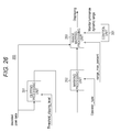
- FIG. 26 illustrates a configuration example of the HDR processing unit 205 .
- the HDR processing unit 205 includes a clipping processing unit 251 , a marking processing unit 252 , and a range mapping processing unit 253 .
- the transmission video data (a) (see FIG. 6 )
- the transmission video data (decoded pixel data) is input to the clipping processing unit 251 , where a process using filter information is executed.
- V_th threshold_clipping_level
- the transmission video data (c) (see FIG. 9 )
- the transmission video data (decoded pixel data) is input to the range mapping processing unit 253 , where a process using conversion curve information is executed.
- the clipping processing unit 251 extracts, as a target for a re-mapping process, pixel data at levels equal to or higher than a level of a threshold clipping level (Threshold_clipping_level) from pixel data constituting the transmission video data, using this threshold clipping level.
- a threshold clipping level (Threshold_clipping_level) becomes V_100.
- FIG. 27( a ) shows a part of pixel data constituting transmission video data, where only pixel data indicated in white corresponds to pixel data at levels equal to or higher than the threshold clipping level.
- the clipping processing unit 251 extracts pixel data indicated as a white part and corresponding to a target of the re-mapping process.
- the HDR processing unit 205 outputs pixel data not corresponding to the target of the re-mapping process without changing values of these data.
- the marking processing unit 252 performs level separation for each pixel data corresponding to the target of the re-mapping process by executing filter type filtering operation indicated by an operator type (Operator_type), while using pixel data around the corresponding pixel data as well.
- FIG. 27( c ) illustrates a state of level separation of the respective pixel data corresponding to the target of the re-mapping process.
- FIG. 27( d ) illustrates three stages of level separation, i.e., (1) “highest level”, (2) “2nd highest level”, and (3) “3rd highest level”. While the stages of level separation are constituted by three stages herein for easy understanding, a larger number of stages are established in an actual situation.
- the range mapping processing unit 253 maps the values of the respective pixel data into values corresponding to the respective stages of level separation, and outputs the results.
- the range mapping processing unit 253 maps the values by using a range max percent (renge_max_percent), i.e., the value N and a monitor luminance dynamic range (Monitor Luminance dynamic range).
- FIG. 28 illustrates an example of range mapping.
- the range max percent (renge_max_percent) is “4”, while the monitor luminance dynamic range (Monitor Luminance dynamic range) is 400%.
- the pixel data of “highest level” is mapped to such a value that the output luminance percentage (Output luminance percentage) corresponding to output luminance of the display unit 207 becomes 400%.
- the pixel data of “2nd highest level” is mapped to such a value that the output luminance percentage becomes 300%.
- the pixel data of “3rd highest level” is mapped to such a value that the output luminance percentage becomes 200%.
- FIG. 29 illustrates another example of range mapping. It is assumed that the marking processing unit 252 separates respective examples from “Case 1” to “Case 4” into two stages of (1) “highest level” and (2) “2nd highest level” for easy understanding of the explanation.
- the range max percent is “8”, while the monitor luminance dynamic range is “800%”.
- the pixel data of (1) “highest level” is mapped to such a value that the output luminance percentage becomes 800%.
- the pixel data of (2) “2nd highest level” is mapped to such a value that the output luminance percentage becomes 400%.
- the range max percent is “4”, while the monitor luminance dynamic range is 800%.
- the pixel data of (1) “highest level” is mapped to such a value that the output luminance percentage becomes 400%.
- the pixel data of (2) “2nd highest level” is mapped to such a value that the output luminance percentage becomes 200%.
- the dynamic range of the video data extends up to 400%. Accordingly, the maximum of the output luminance percentage is so selected as to correspond to 400% of the dynamic range of the video data even when the dynamic range of the monitor luminance extends up to 800%. As a result, unnecessary brightness and unnaturalness of the high-luminance part is reducible.
- the range max percent is “8”, while the monitor luminance dynamic range is 400%.
- the pixel data of (1) “highest level” is mapped to such a value that the output luminance percentage becomes 400%.
- the pixel data of (2) “2nd highest level” is mapped to such a value that the output luminance percentage becomes 200%.
- the dynamic range of the monitor luminance extends up to 400%. Accordingly, the maximum of the output luminance percentage is so selected as to correspond to 400% of the dynamic range of the video data even when the dynamic range of the monitor luminance extends up to 400%.
- video data for display coinciding with the dynamic range of the monitor luminance is obtainable, wherefore a blown-out state on the high-luminance side, i.e., so-called blown-out highlights state is avoidable.
- the range max percent is “8”, while the monitor luminance dynamic range is 100%.
- the pixel data of (1) “highest level” is mapped to such a value that the output luminance percentage becomes 100%.
- the pixel data of (2) “2nd highest level” is mapped to such a value that the output luminance percentage becomes lower than 100%.
- the range mapping processing unit 253 maps values of respective pixel data in a conversion target level range from V_th to V_100*N contained in transmission video data with reference to a table of a mapping curve (mapping curve), and outputs the mapped values as output data.
- the conversion curve used in this case is a conversion curve having a range max percent (renge_max_percent), i.e., the maximum level after conversion determined by using the value N and the monitor luminance dynamic range (Monitor Luminance dynamic range).
- the maximum level after conversion is determined in a manner similar to the manner when the filter information is used as discussed above (see FIG. 29 ).
- the maximum level to be determined is such a value that the output luminance percentage becomes 800%.
- the maximum level to be determined is such a value that the output luminance percentage becomes 400%.
- values of the respective pixel data out of the conversion target level range are used as output from the range mapping processing unit 253 without a change, and therefore used as output from the HDR processing unit 205 .
- FIG. 30 illustrates an example (Case 5) of range mapping.
- the range max percent (renge_max_percent) is “4”
- the monitor luminance dynamic range (Monitor Luminance dynamic range) is 200%.
- the maximum level to be determined is such a value that the output luminance percentage becomes 200%.
- the maximum level of the transmission video data “960” is converted to a level “480”.
- the range mapping processing unit 253 uses information on the monitor luminance dynamic range (Monitor Luminance dynamic range).
- monitor luminance dynamic range is allowed to be determined based on information obtained from EDID on the monitor side via HDMI.
- the “Range_max_percent”, and respective elements of the SEI message and the descriptor are allowed to be shared between the set top box and the monitor when these elements are defined in Vender Specific Info Frame.
- HDMI is a registered trademark.
- the reception unit 202 receives a transport stream TS transmitted from the transmitting device 100 while carried on broadcasting waves.
- This transport stream TS is supplied to the system decoder 203 .
- the system decoder 203 extracts a video stream (elementary stream) from this transport stream TS.
- the system decoder 203 further extracts an HDR simple descriptor (HDR_simple descriptor) or an HDR full descriptor (HDR_full descriptor) from this transport stream TS, and transmits the extracted descriptor to the control unit 201 .
- HDR simple descriptor HDR_simple descriptor
- HDR full descriptor HDR_full descriptor
- the control unit 201 recognizes whether or not tone mapping SEI information and HDR conversion SEI information have been inserted into the video stream based on this descriptor.
- the control unit 203 is enabled to control the video decoder 204 such that the video decoder 204 positively acquires the SEI information, for example.
- the video stream extracted by the system decoder 204 is supplied to the video decoder 204 .
- the video decoder 204 performs a decoding process for the video stream to generate baseband video data.
- the video decoder 204 further extracts the SEI message inserted into this video stream, and transmits the extracted SEI message to the control unit 201 .
- This SEI message contains a tone mapping information SEI message (Tone mapping information SEI message) and an HDR conversion SEI message (HDR conversion SEI message).
- the control unit 201 controls the decoding process and a display process based on the SEI information.
- the video data obtained by the video decoder 204 (transmission video data) is supplied to the HDR processing unit 205 .
- the HDR processing unit 205 converts the high-level side level range of the transmission video data such that the maximum level of the transmission video data becomes a predetermined level based on auxiliary information.
- the YUV color space of the video data obtained by the HDR processing unit 206 is converted into the RGB color space by the color space conversion unit 206 .
- the video data after the color space conversion is supplied to the display unit 207 .
- the display unit 207 displays an image corresponding to reception video data with a luminance dynamic range of the transmitted video data, and further with a luminance dynamic range in accordance with the luminance dynamic range of the monitor.
- the transmitting device 100 in the transmitting and receiving system 10 illustrated in FIG. 1 transmits transmission video data obtained by applying a gamma curve to input video data having a level range from 0% to 100%*N, together with transmission of auxiliary information used for converting high-luminance levels on the receiving side.
- the receiving side is capable of converting high-luminance levels of the transmission video data based on this auxiliary information, for example, wherefore the receiving side is capable of realizing display with an appropriate luminance dynamic range.
- the transmitting and receiving system 10 illustrated in FIG. 1 inserts, into a layer of a transport stream TS transmitted from the transmitting device 100 to the receiving device 200 , identification information indicating that auxiliary information has been inserted into a layer of a video stream. Accordingly, insertion of the auxiliary information into the video stream is recognizable without the necessity of decoding the video stream, wherefore appropriate extraction of the auxiliary information from the video stream is realizable.
- a container constituted by a transport stream MPEG-2 TS
- MP4 or other format containers are often used for distribution.
- FIG. 31 illustrates a configuration example of a stream distribution system 30 .
- This stream distribution system 30 is a MPEG-DASH base stream distribution system.
- N pieces of IPTV clients 33 - 1 , 33 - 2 , and up to 33 -N are connected with a DASH segment streamer 31 and a DASH MPD server 32 via CDN (Content Delivery Network) 34 .
- CDN Content Delivery Network
- the DASH segment streamer 31 generates DASH specification stream segments (hereinafter referred to as “DASH segments”) based on media data of predetermined content (such as video data, audio data, and subtitle data), and transmits the segments in response to an HTTP request from an IPTV client.
- DASH segments DASH specification stream segments
- the DASH segment streamer 31 may be a server dedicated for streaming, or a server functioning as a web (Web) server as well.
- the DASH segment streamer 31 further transmits segments of a predetermined stream to the IPTV clients 33 as a request source via the CDN 34 in response to a request for the segments of the corresponding stream transmitted from the IPTV clients 33 ( 33 - 1 , 33 - 2 , and up to 33 -N) via a CDN 14 .
- the IPTV clients 33 select and request a stream having an optimum rate in accordance with the state of the network environment where each client is present, with reference to a value of a rate described in an MPD (Media Presentation Description) file.
- MPD Media Presentation Description
- the DASH MPD server 32 is a server which generates an MPD file used for acquiring DASH segments generated by the DASH segment streamer 31 .
- the MPD file is generated based on content metadata received from a content management server (not shown in FIG. 31 ), and an address (url) of the segments generated by the DASH segment streamer 31 .
- respective attributes are described by utilizing elements called representations (Representations) for each of streams such as video streams and audio streams.
- representations representations
- a rate is described in an MPD file for each of representations separated in correspondence with a plurality of video data streams having different rates.
- the IPTV clients 33 are capable of selecting an optimum stream in accordance with the respective network environments where the IPTV clients 33 are present, with reference to the values of the rates as discussed above.
- FIG. 32 illustrates an example of relationships between respective structures disposed in the foregoing MPD file in a hierarchical manner. As illustrated in (a) of FIG. 32 , there exist a plurality of periods (Periods) sectioned at time intervals in a media presentation (Media Presentation) as the whole MPD file. For example, an initial period starts from 0 second, while a subsequent period starts from 100 seconds.
- Periods Periods
- Media Presentation media presentation
- a period contains a plurality of representations (Representations).
- the plurality of representations include representation groups grouped in accordance with adaptation sets (AdaptationSets) described above, and associated with video data streams having different stream attributes, such as rates, and containing identical contents.
- AdaptationSets adaptation sets
- a representation includes a segment info (SegmentInfo).
- this segment info includes an initialization segment (Initialization Segment), and a plurality of media segments (Media Segments) each of which describes information on a corresponding segment (Segment) divided from a period.
- Media Segments each of which describes information on a corresponding segment (Segment) divided from a period.
- Each of the media segments includes information on an address (url) and the like for actually acquiring video and audio segment data and other segment data.
- a stream is freely switchable between a plurality of representations grouped in accordance with adaptation sets. Accordingly, a stream having an optical rate is selectable in accordance with the network environment where each of the IPTV clients is present, wherefore continuous movie distribution is achievable.
- FIG. 33( a ) illustrates a segment structure. Segments are dividable into three types based on differences of constituent elements.
- a first structure includes a plurality of “Media Segments” for storing fragmented movie data, in addition to codec initialization information “Initialization Segment”.
- a second structure includes only one “Media Segment”.
- a third structure includes a “Media Segment” integrated with the codec initialization information “Initialization Segment”.
- FIGS. 33( b ) and 33( c ) illustrate examples of the data format of segments corresponding to ISOBMFF and MPEG-2TS when the structure including only one “Media Segment is used.
- a video stream into which a tone mapping information SEI message (Tone mapping information SEI message) and an HDR conversion SEI message (HDR conversion SEI message) have been inserted is disposed at the position of “Media Segment”.
- a tone mapping information SEI message Tone mapping information SEI message
- an HDR conversion SEI message HDR conversion SEI message
- an HDR simple descriptor HDR_simple descriptor
- an HDR full descriptor HDR_full descriptor
- level_mapping_curve descriptor level_mapping_curve descriptor
- FIG. 34 schematically illustrates information within a transport stream, which information corresponds to the information contained in “Initialization Segment” and the information contained in “Media Segment” in the data format of segments corresponding to MPEG-2TS (see FIG. 33( c ) ).
- the IPTV clients 33 ( 33 - 1 , 33 - 2 and up to 33 -N) of the MPEG-DASH base stream distribution system 30 acquire “Initialization Segment” and “Media Segment” based on information on an address (url) present in the MPD file, and displays an image.
- the SEI message containing gamma curve information and additional information for re-mapping is similarly inserted into a layer of a video stream.
- a descriptor containing identification information indicating the presence or absence of insertion of the SEI message is inserted into a system layer (layer of container).
- the IPTV clients 33 are capable of executing processing in a similar manner to the manner of the receiving device 200 of the transmitting and receiving system 10 illustrated in FIG. 1 .
- MMT MPEG Media Transport
- FIG. 35 illustrates a configuration example of a transmitting and receiving system 40 which handles the MMT structure transmission stream.
- the transmitting and receiving system 40 includes a transport packet transmitting device 300 , and a transport packet receiving device 400 .
- the transmitting device 300 generates a transport packet having MMT structure (see ISO/IEC CD 23008-1), i.e., a transmission stream containing an MMT packet, and transmits the generated transmission stream to the receiving side via an RF transmission path or a communication network transmission path.
- This transmission stream is a multiplex stream which includes a first MMT packet containing video and audio transmission media as a payload, and a second MMT packet containing information concerning transmission media as a payload, in a time sharing manner and at least in a size of a fragmented packet.
- the receiving device 400 receives the foregoing transmission stream from the transmitting side via an RF transmission path or a communication network transmission path.
- the receiving device 400 processes transmission media extracted from the transmission stream by using a decode time and a display time acquired based on time information, so as to display an image and output a voice.
- FIG. 36 illustrates a configuration of an MMT packet in a tree form.
- the MMT packet is constituted by an MMT packet header (MMT Packet Header), an MMT payload header (MMT Payload Header), and an MMT payload (MMT Payload).
- MMT payload contains a message (Message), an MPU (Media Processing Unit), an FEC repair symbol (FEC Repair Symbol), and others. Signaling of these is executed based on a payload type (payload + type) contained in the MMT payload header.
- MFU MFU Fragment Unit
- MFU Header MFU header
- MMT packet containing the respective MPUs is identifiable based on a packet ID (Packet_ID) existing in the MMT packet header.
- an MMT payload disposed as an MMT payload is such a video stream which contains insertion of tone mapping information SEI message (Tone mapping information SEI message) and an HDR conversion SEI message (HDR conversion SEI message).
- a message which has an HDR description table (HDR description table) containing contents similar to the contents of the foregoing HDR simple descriptor (HDR_simple descriptor) or HDR full descriptor (HDR_full descriptor) and a level mapping curve descriptor (level_mapping_curve descriptor), for example.
- FIG. 37 illustrates a structure example (Syntax) of an HDR description message (HDR description Message) having a HDR simple description table.
- a 16-bit field of “message_id” indicates that the structure is an HDR description message.
- An 8-bit filed of “version” indicates a version of this message.
- a 16-bit field of “length” indicates a length (size) of this message, showing a byte count of the subsequent part.
- This HDR description message contains an HDR simple description table (HDR simple description table).
- FIG. 38 illustrates a structure example (Syntax) of an HDR simple description table.
- An 8-bit field of “table_id” indicates that the structure is an HDR simple description table.
- An 8-bit field of “version” indicates a version of this table. In this case, “table_id” and “version” are uniquely allocated in the system.
- a 16-bit field of “length” indicates a whole (size) of this table.
- a 16-bit field of “packet_id” is identical to “packet_id” contained in the MMT packet header. This structure allows asset-level association.
- a 1-bit field of “tone_mapping_SEI_existed” is flag information which indicates whether or not tone mapping SEI information (gamma curve information) is present in a video layer (layer of video stream) similarly to the HDR simple descriptor (HDR_simple_descriptor) illustrated in FIG. 18 .
- “1” indicates that the tone mapping SEI information is present, while “0” indicates that the tone mapping SEI information is absent.
- HDR_conversion_SEI_existed is flag information which indicates whether or not HDR conversion SEI information (additional information) is present in the video layer (layer of video stream) similarly to the HDR simple descriptor (HDR_simple_descriptor) illustrated in FIG. 18 .
- “1” indicates that the HDR conversion SEI information is present, while “0” indicates that the HDR conversion SEI information is absent.
- FIG. 39 illustrate another structure example (Syntax) of an HDR description message (HDR description Message) having an HDR description table.
- a 16-bit field of “message_id” indicates that the structure is an HDR description message.
- An 8-bit filed of “version” indicates a version of this message.
- a 16-bit field of “length” indicates a length (size) of this message, showing a byte count of the subsequent part.
- This HDR description message contains an HDR full description table (HDR full description table).
- FIG. 40 illustrates a structure example (Syntax) of an HDR full description table.
- An 8-bit field of “table_id” indicates that the structure is an HDR simple description table.
- An 8-bit field of “version” indicates a version of this table. In this case, “table_id” and “version” are uniquely allocated in the system.
- a 16-bit field of “length” indicates a whole (size) of this table.
- a 16-bit field of “packet_id” is identical to “packet_id” contained in the MMT packet header. This structure allows asset-level association.
- this HDR full description table contains “tone_mapping_SEI_existed” and “HDR_conversion_SEI_existed”, and further information similar to the corresponding information of the HDR full descriptor (HDR_full descriptor) illustrated in FIG. 20 .
- FIG. 41 is a view illustrating a configuration example of an HDR description message having a level mapping curve table.
- a 16-bit field of “message_id” indicates that the structure is an HDR description message.
- An 8-bit filed of “version” indicates a version of this message.
- a 16-bit field of “length” indicates a length (size) of this message, showing a byte count of the subsequent part.
- This HDR description message contains a level mapping curve table (Level_mapping_curve_table).
- FIG. 42 illustrates a structure example (Syntax) of a level mapping curve table.
- An 8-bit field of “table_id” indicates that the structure is a level mapping curve table.
- An 8-bit field of “version” indicates a version of this table. In this case, “table_id” and “version” are uniquely allocated in the system.
- a 16-bit field of “length” indicates a whole (size) of this table.
- a 16-bit field of “packet_id” is identical to “packet_id” contained in the MMT packet header. This structure allows asset-level association.
- mapping_curve_table_id “number of levels N”, “number of curve types C”, and “curve_data” are contained, similarly to the level mapping curve descriptor (level_mapping_curve_descriptor) illustrated in FIG. 21 .
- the IPTV clients 33 ( 33 - 1 , 33 - 2 and up to 33 -N) of the MPEG-DASH base stream distribution system 30 acquire “Initialization Segment” and “Media Segment” based on information on an address (url) present in the MPD file, and displays an image.
- processing using the SEI message is achievable similarly to the receiving device 200 of the transmitting and receiving system 10 illustrated in FIG. 1 .
- the SEI message containing gamma curve information and additional information for re-mapping is similarly inserted into the layer of the video stream.
- the description table containing identification information indicating the presence or absence of insertion of the SEI message is inserted into the system layer (layer of container). Accordingly, processing similar to the processing of the receiving device 200 of the transmitting and receiving system 10 illustrated in FIG. 1 is achievable by the transport packet receiving device 400 .
- the present technology may have the following configurations.
- a transmitting device including:
- a processing unit that applies a gamma curve to input video data having a level range from 0% to 100%*N (N: a number larger than 1) to obtain transmission video data;
- a transmission unit that transmits the transmission video data together with auxiliary information used for converting a high-luminance level on a receiving side.
- the transmission unit transmits a container in a predetermined format that contains a video stream obtained by encoding the transmission video data
- an auxiliary information insertion unit that inserts the auxiliary information into a layer of the video stream and/or a layer of the container is provided.
- the transmitting device including an identification information insertion unit that inserts, into the layer of the container, identification information that indicates that the auxiliary information has been inserted into the layer of the video stream.
- auxiliary information contains information on a filter applied to pixel data of the transmission video data at a level corresponding to 100% of the input video data.
- the transmitting device any one of (1) through (3) noted above, wherein the processing unit further executes a process for converting a level of output video data obtained by applying the gamma curve to the input video data, which level corresponds to a level of the input video data in a range from a threshold equal to or lower than a level corresponding to 100% to 100%*N, into a level in a range from the threshold to a level corresponding to 100% of the input video data so as to obtain the transmission video data.
- auxiliary information contains information on a filter applied to pixel data of the transmission video data in a range from the threshold to a level corresponding to 100% of the input video data.
- auxiliary information contains information on a conversion curve applied to pixel data of the transmission video data in a range from the threshold to a level corresponding to 100% of the input video data.
- a transmitting method including:
- a processing step that applies a gamma curve to input video data having a level range from 0% to 100%*N (N: a number larger than 1) to obtain transmission video data;
- a transmission step that transmits the transmission video data together with auxiliary information used for converting a high-luminance level on a receiving side.
- a receiving device including:
- a reception unit that receives transmission video data obtained by applying a gamma curve to input video data having a level range from 0% to 100%*N (N: a number larger than 1);
- a processing unit that converts a high-level side level range of the transmission video data such that a maximum level becomes a predetermined level based on auxiliary information received together with the transmission video data.
- the transmission video data is video data obtained by further executing a process for converting a level of output video data obtained by applying the gamma curve to the input video data, which level corresponds to a level of the input video data in a range from 100% to 100%*N, into a level corresponding to 100% of the input video data, and
- the processing unit converts levels of respective pixel data corresponding to 100% of the input video data into levels in a range from a level corresponding to 100% of the input video data to the predetermined level by applying a filter specified in filter information contained in the auxiliary information.
- the transmission video data is video data obtained by further executing a process for converting a level of output video data obtained by applying the gamma curve to the input video data, which level corresponds to a level of the input video data in a range from a threshold equal to or lower than a level corresponding to 100% to 100%*N, into a level in a range from the threshold to a level corresponding to 100% of the input video data, and
- the processing unit converts levels of respective pixel data of the transmission video data in a range from the threshold to a level corresponding to 100% of the input video data into levels in a range from the threshold to the predetermined level by applying a filter specified in filter information contained in the auxiliary information.
- the transmission video data is video data obtained by further executing a process for converting a level of output video data obtained by applying the gamma curve to the input video data, which level corresponds to a level of the input video data in a range from a threshold equal to or lower than a level corresponding to 100% to 100%*N, into a level in a range from the threshold to a level corresponding to 100% of the input video data, and
- the processing unit converts levels of respective pixel data of the transmission video data in a range from the threshold to a level corresponding to 100% of the input video data into levels in a range from the threshold to the predetermined level by applying conversion curve information contained in the auxiliary information.
- the transmission video data is output video data without a change, which output video data is obtained by applying the gamma curve to the input video data, and
- the processing unit converts levels of respective pixel data of the transmission video data in a range from a threshold equal to or lower than a level corresponding 100% of the input video data to a level corresponding to 100%*N of the input video data into levels in a range from the threshold to the predetermined level corresponding to L %*100 (L: a number equal to or smaller than N) of the input video data by applying conversion curve information contained in the auxiliary information.
- a receiving method including:
- a reception step that receives transmission video data obtained by applying a gamma curve to input video data having a level range from 0% to 100%*N (N: a number larger than 1);
- a processing step that converts a high-level side level range of the transmission video data such that a maximum level becomes a predetermined level based on auxiliary information received together with the transmission video data.
- the present technology is chiefly characterized in that transmission video data obtained by applying a gamma curve to input video data with HDR is transmitted together with auxiliary information (filter information and conversion curve information) used for converting a high-luminance level on the receiving side so as to realize display with an appropriate luminance dynamic range on the receiving side (see FIG. 10 ).
Landscapes
- Engineering & Computer Science (AREA)
- Multimedia (AREA)
- Signal Processing (AREA)
- Picture Signal Circuits (AREA)
- Two-Way Televisions, Distribution Of Moving Picture Or The Like (AREA)
- Compression Or Coding Systems Of Tv Signals (AREA)
- Studio Devices (AREA)
Priority Applications (1)
| Application Number | Priority Date | Filing Date | Title |
|---|---|---|---|
| US19/309,709 US20260059069A1 (en) | 2013-04-30 | 2025-08-26 | Transmitting device, transmitting method, receiving device, and receiving method |
Applications Claiming Priority (3)
| Application Number | Priority Date | Filing Date | Title |
|---|---|---|---|
| JP2013096056 | 2013-04-30 | ||
| JP2013-096056 | 2013-04-30 | ||
| PCT/JP2014/060877 WO2014178286A1 (fr) | 2013-04-30 | 2014-04-16 | Dispositif d'émission, procédé d'émission, dispositif de réception et procédé de réception |
Related Parent Applications (1)
| Application Number | Title | Priority Date | Filing Date |
|---|---|---|---|
| PCT/JP2014/060877 A-371-Of-International WO2014178286A1 (fr) | 2013-04-30 | 2014-04-16 | Dispositif d'émission, procédé d'émission, dispositif de réception et procédé de réception |
Related Child Applications (1)
| Application Number | Title | Priority Date | Filing Date |
|---|---|---|---|
| US15/829,388 Continuation US10560674B2 (en) | 2013-04-30 | 2017-12-01 | Transmitting device, transmitting method, receiving device, and receiving method |
Publications (2)
| Publication Number | Publication Date |
|---|---|
| US20160080714A1 US20160080714A1 (en) | 2016-03-17 |
| US9860505B2 true US9860505B2 (en) | 2018-01-02 |
Family
ID=51843420
Family Applications (5)
| Application Number | Title | Priority Date | Filing Date |
|---|---|---|---|
| US14/784,353 Active US9860505B2 (en) | 2013-04-30 | 2014-04-16 | Transmitting device, transmitting method, receiving device, and receiving method |
| US15/829,388 Active US10560674B2 (en) | 2013-04-30 | 2017-12-01 | Transmitting device, transmitting method, receiving device, and receiving method |
| US16/736,218 Active US11575866B2 (en) | 2013-04-30 | 2020-01-07 | Transmitting device, transmitting method, receiving device, and receiving method |
| US18/077,550 Active 2034-06-11 US12425656B2 (en) | 2013-04-30 | 2022-12-08 | Transmitting device, transmitting method, receiving device, and receiving method |
| US19/309,709 Pending US20260059069A1 (en) | 2013-04-30 | 2025-08-26 | Transmitting device, transmitting method, receiving device, and receiving method |
Family Applications After (4)
| Application Number | Title | Priority Date | Filing Date |
|---|---|---|---|
| US15/829,388 Active US10560674B2 (en) | 2013-04-30 | 2017-12-01 | Transmitting device, transmitting method, receiving device, and receiving method |
| US16/736,218 Active US11575866B2 (en) | 2013-04-30 | 2020-01-07 | Transmitting device, transmitting method, receiving device, and receiving method |
| US18/077,550 Active 2034-06-11 US12425656B2 (en) | 2013-04-30 | 2022-12-08 | Transmitting device, transmitting method, receiving device, and receiving method |
| US19/309,709 Pending US20260059069A1 (en) | 2013-04-30 | 2025-08-26 | Transmitting device, transmitting method, receiving device, and receiving method |
Country Status (8)
| Country | Link |
|---|---|
| US (5) | US9860505B2 (fr) |
| EP (2) | EP3926963A3 (fr) |
| JP (3) | JP6510404B2 (fr) |
| KR (1) | KR102241672B1 (fr) |
| CN (2) | CN105165001B (fr) |
| BR (1) | BR112015026979B1 (fr) |
| RU (1) | RU2657473C2 (fr) |
| WO (1) | WO2014178286A1 (fr) |
Cited By (5)
| Publication number | Priority date | Publication date | Assignee | Title |
|---|---|---|---|---|
| US20180070083A1 (en) * | 2015-03-24 | 2018-03-08 | Sony Corporation | Transmission device, transmission method, reception device, and reception method |
| US10560674B2 (en) | 2013-04-30 | 2020-02-11 | Saturn Licensing Llc | Transmitting device, transmitting method, receiving device, and receiving method |
| US10997454B2 (en) | 2016-02-25 | 2021-05-04 | Canon Kabushiki Kaisha | Information-processing apparatus and information-processing method for generating waveform information of input image data |
| US11394920B2 (en) * | 2014-12-29 | 2022-07-19 | Sony Corporation | Transmission device, transmission method, reception device, and reception method |
| US20250294157A1 (en) * | 2023-09-13 | 2025-09-18 | Sharp Nec Display Solutions, Ltd. | Display system, display method, display controller, and video signal processing method for display controller |
Families Citing this family (67)
| Publication number | Priority date | Publication date | Assignee | Title |
|---|---|---|---|---|
| WO2014052449A1 (fr) | 2012-09-25 | 2014-04-03 | The Board Of Trustees Of The University Of Arkansas | Dispositif et méthode pour le diagnostic photoacoustique in vivo et la purge photothermique du sang infecté |
| JP2015005878A (ja) * | 2013-06-20 | 2015-01-08 | ソニー株式会社 | 再生装置、再生方法、および記録媒体 |
| US20150032845A1 (en) * | 2013-07-26 | 2015-01-29 | Samsung Electronics Co., Ltd. | Packet transmission protocol supporting downloading and streaming |
| CA2936313C (fr) | 2014-01-24 | 2022-07-19 | Sony Corporation | Dispositif de transmission, methode de transmission, dispositif de reception et methode de reception |
| US10306306B2 (en) * | 2014-05-12 | 2019-05-28 | Sony Corporation | Communication device and communication method to process images |
| WO2015174026A1 (fr) | 2014-05-16 | 2015-11-19 | パナソニックIpマネジメント株式会社 | Procédé et dispositif de conversion |
| JP6531759B2 (ja) * | 2014-06-13 | 2019-06-19 | ソニー株式会社 | 送信装置、送信方法、受信装置および受信方法 |
| WO2015198560A1 (fr) | 2014-06-27 | 2015-12-30 | パナソニックIpマネジメント株式会社 | Dispositif de délivrance de données, procédé de délivrance de données et procédé de génération de données |
| JP6466258B2 (ja) | 2014-08-07 | 2019-02-06 | パナソニック インテレクチュアル プロパティ コーポレーション オブ アメリカPanasonic Intellectual Property Corporation of America | 再生装置、再生方法および記録媒体 |
| WO2016021120A1 (fr) * | 2014-08-07 | 2016-02-11 | パナソニック インテレクチュアル プロパティ コーポレーション オブ アメリカ | Dispositif de reproduction, procédé de reproduction et support d'enregistrement |
| US9800898B2 (en) | 2014-10-06 | 2017-10-24 | Microsoft Technology Licensing, Llc | Syntax structures indicating completion of coded regions |
| KR102360613B1 (ko) * | 2014-11-07 | 2022-02-09 | 소니그룹주식회사 | 송신 장치, 송신 방법, 수신 장치 및 수신 방법 |
| US10623805B2 (en) | 2014-11-17 | 2020-04-14 | Sony Corporation | Sending device, method of sending high dynamic range image data, receiving device, and method of receiving high dynamic range image data |
| WO2016078094A1 (fr) * | 2014-11-21 | 2016-05-26 | SZ DJI Technology Co., Ltd. | Système et procédé de mélange adaptatif rapide pour formation d'image à plage dynamique élevée |
| JP6601729B2 (ja) * | 2014-12-03 | 2019-11-06 | パナソニックIpマネジメント株式会社 | データ生成方法、データ再生方法、データ生成装置及びデータ再生装置 |
| FI4109906T3 (fi) | 2014-12-03 | 2024-01-30 | Panasonic Ip Man Co Ltd | Datangenerointilaite |
| WO2016089093A1 (fr) * | 2014-12-04 | 2016-06-09 | 엘지전자 주식회사 | Procédé et dispositif de transmission et de réception d'un signal de radiodiffusion |
| JP2016122985A (ja) * | 2014-12-25 | 2016-07-07 | 株式会社東芝 | 画像処理システム、画像処理装置および画像処理方法 |
| EP3261339B1 (fr) * | 2015-02-16 | 2022-01-05 | Sony Group Corporation | Dispositif de traitement d'informations, support d'enregistrement d'informations et procédé de traitement d'informations, et programme |
| JP6702300B2 (ja) * | 2015-03-05 | 2020-06-03 | ソニー株式会社 | 送信装置、送信方法、受信装置および受信方法 |
| JP6463179B2 (ja) * | 2015-03-17 | 2019-01-30 | キヤノン株式会社 | 信号処理装置、信号処理方法および撮像装置 |
| CN107534798A (zh) * | 2015-04-22 | 2018-01-02 | Lg 电子株式会社 | 广播信号发送设备、广播信号接收设备、广播信号发送方法和广播信号接收方法 |
| JP6666022B2 (ja) * | 2015-06-04 | 2020-03-13 | キヤノン株式会社 | 画像表示装置、画像出力装置、及び、それらの制御方法 |
| EP3304881B1 (fr) * | 2015-06-05 | 2022-08-10 | Apple Inc. | Rendu et affichage d'un contenu à grande gamme dynamique |
| US10681107B2 (en) | 2015-06-16 | 2020-06-09 | Apple Inc. | Adaptive video content for cellular communication |
| JP6844539B2 (ja) * | 2015-07-31 | 2021-03-17 | ソニー株式会社 | 映像信号処理装置および映像信号処理方法、ならびに表示装置 |
| JP2018530942A (ja) * | 2015-08-24 | 2018-10-18 | トムソン ライセンシングThomson Licensing | コード化および復号方法ならびに対応するデバイス |
| US10140694B2 (en) * | 2015-08-31 | 2018-11-27 | Lg Electronics Inc. | Image display apparatus |
| JP6820507B2 (ja) * | 2015-09-14 | 2021-01-27 | パナソニックIpマネジメント株式会社 | 映像受信方法、映像送信方法、映像受信装置及び映像送信装置 |
| CN112954353B (zh) | 2015-09-14 | 2024-09-13 | 松下知识产权经营株式会社 | 解码装置和解码方法 |
| KR102243844B1 (ko) | 2015-09-23 | 2021-04-22 | 애리스 엔터프라이지즈 엘엘씨 | 비디오 디코더에서의 높은 동적 범위 적응 동작들 |
| CN113660525A (zh) | 2015-09-25 | 2021-11-16 | 麦克赛尔株式会社 | 接收装置 |
| JP6645869B2 (ja) * | 2015-09-29 | 2020-02-14 | マクセル株式会社 | 放送システム |
| JP6616212B2 (ja) * | 2015-09-28 | 2019-12-04 | マクセル株式会社 | 表示制御方法 |
| JP6645871B2 (ja) * | 2015-09-30 | 2020-02-14 | マクセル株式会社 | 放送システム |
| WO2017051808A1 (fr) | 2015-09-25 | 2017-03-30 | 日立マクセル株式会社 | Dispositif de réception de radiodiffusion |
| JP6616211B2 (ja) * | 2015-09-25 | 2019-12-04 | マクセル株式会社 | 放送受信装置 |
| JP6441247B2 (ja) * | 2015-10-01 | 2018-12-19 | マクセル株式会社 | 表示制御方法 |
| JP6830190B2 (ja) * | 2015-10-07 | 2021-02-17 | パナソニックIpマネジメント株式会社 | 映像送信方法、映像受信方法、映像送信装置及び映像受信装置 |
| WO2017061071A1 (fr) * | 2015-10-07 | 2017-04-13 | パナソニックIpマネジメント株式会社 | Procédé d'émission vidéo, procédé de réception de vidéo, dispositif d'émission vidéo et dispositif de réception de vidéo |
| WO2017061297A1 (fr) * | 2015-10-09 | 2017-04-13 | ソニー株式会社 | Dispositif de traitement d'informations et procédé de traitement d'informations |
| JP6519441B2 (ja) | 2015-10-22 | 2019-05-29 | ソニー株式会社 | 送信装置、送信方法、受信装置および受信方法 |
| KR102801527B1 (ko) | 2015-10-28 | 2025-04-30 | 인터디지털 브이씨 홀딩스 인코포레이티드 | 정보 데이터의 공통 세트에 의해 구동되는 후보 프로세스들의 세트로부터 비디오 데이터에 적용될 프로세스를 선택하기 위한 방법 및 디바이스 |
| KR102577659B1 (ko) | 2015-11-09 | 2023-09-13 | 인터디지털 브이씨 홀딩스 인코포레이티드 | 기본 스트림들로부터 디코딩된 비디오 콘텐츠를 디스플레이의 특성들에 적응시키기 위한 방법 및 디바이스 |
| JP6132006B1 (ja) * | 2015-12-02 | 2017-05-24 | 日本電気株式会社 | 映像符号化装置、映像システム、映像符号化方法、及び映像符号化プログラム |
| PL3235236T3 (pl) | 2015-12-17 | 2018-11-30 | Koninklijke Philips N.V. | Kodowanie zakresu dynamicznego dla obrazów i wideo |
| KR102446181B1 (ko) * | 2016-02-17 | 2022-09-22 | 삼성전자주식회사 | 멀티미디어 시스템에서 미디어 데이터를 송수신하는 방법 및 장치 |
| JP6460014B2 (ja) | 2016-03-04 | 2019-01-30 | ソニー株式会社 | 信号処理装置、信号処理方法およびカメラシステム |
| EP3220645A1 (fr) | 2016-03-18 | 2017-09-20 | Thomson Licensing | Procédé et dispositif permettant de coder une image à plage dynamique élevée, procédé et dispositif de décodage correspondants |
| JP6682322B2 (ja) * | 2016-03-31 | 2020-04-15 | シャープ株式会社 | 階調値変換装置、テレビジョン受像機、階調値変換方法、制御プログラム、および記録媒体 |
| US10587934B2 (en) * | 2016-05-24 | 2020-03-10 | Qualcomm Incorporated | Virtual reality video signaling in dynamic adaptive streaming over HTTP |
| CN106101679B (zh) * | 2016-08-23 | 2018-01-12 | 青岛海信电器股份有限公司 | 高动态范围信号的处理方法及处理系统 |
| US10834153B2 (en) * | 2016-08-24 | 2020-11-10 | Qualcomm Incorporated | System level signaling of SEI tracks for media data streaming |
| JP7113746B2 (ja) * | 2016-10-11 | 2022-08-05 | ソニーグループ株式会社 | 送信装置、送信方法、受信装置および受信方法 |
| JP6883971B2 (ja) * | 2016-10-24 | 2021-06-09 | キヤノン株式会社 | 画像処理装置及び画像処理方法、プログラム、並びに記憶媒体 |
| EP3389278B1 (fr) * | 2016-11-22 | 2022-10-12 | Saturn Licensing, LLC | Dispositif et procédé d'émission, dispositif et procédé de réception |
| CN119629402A (zh) * | 2017-10-12 | 2025-03-14 | 索尼公司 | 接收设备和接收方法 |
| CN109605429B (zh) * | 2018-12-06 | 2020-10-09 | 蒋玉素 | 可清洗型弯头式去胡刀 |
| US11265580B2 (en) * | 2019-03-22 | 2022-03-01 | Tencent America LLC | Supplemental enhancement information messages for neural network based video post processing |
| JP7365133B2 (ja) | 2019-04-19 | 2023-10-19 | キヤノン株式会社 | 通信装置およびその制御方法、プログラム |
| JP6958645B2 (ja) * | 2019-04-25 | 2021-11-02 | ソニーグループ株式会社 | 送信装置、送信方法、受信装置および受信方法 |
| JP6658944B2 (ja) * | 2019-04-25 | 2020-03-04 | ソニー株式会社 | 送信装置、送信方法、受信装置および受信方法 |
| US10855998B1 (en) * | 2019-07-01 | 2020-12-01 | Sony Corporation | Embedded codec circuitry for block based gamma correction of a raw image block |
| CN112686809B (zh) | 2019-10-18 | 2024-11-22 | 华为技术有限公司 | 处理高动态范围图像的方法和装置 |
| EP4302480A4 (fr) * | 2021-04-02 | 2024-07-31 | Beijing Bytedance Network Technology Co., Ltd. | Informations de dimension d'échelonnabilité dans un codage vidéo |
| JP7786120B2 (ja) * | 2021-10-12 | 2025-12-16 | ヤマハ株式会社 | 映像信号処理方法及び映像信号処理装置 |
| US20250106410A1 (en) * | 2022-02-01 | 2025-03-27 | Dolby Laboratories Licensing Corporation | Beta scale dynamic display mapping |
Citations (12)
| Publication number | Priority date | Publication date | Assignee | Title |
|---|---|---|---|---|
| US5534948A (en) * | 1989-08-15 | 1996-07-09 | Rank Cintel Limited | Method and apparatus for reducing the effect of alias components produced through non-linear digital signal processing, such as gamma correction, by selective attenuation |
| US6100938A (en) * | 1996-07-16 | 2000-08-08 | Lg Electronics Inc. | Gamma correction circuit for television receiver |
| JP2005287037A (ja) | 1993-07-16 | 2005-10-13 | Sony Corp | 編集システム |
| JP2006287323A (ja) | 2005-03-31 | 2006-10-19 | Nikon Corp | 撮像装置 |
| JP2007049329A (ja) | 2005-08-09 | 2007-02-22 | Seiko Epson Corp | 画像記録装置、画像記録方法、画像表示装置、画像表示方法、及び画像表示システム |
| US20070132866A1 (en) * | 2005-12-10 | 2007-06-14 | Samsung Electronics Co., Ltd. | Image capture device and method, and recording medium storing program for performing the method |
| US20080231688A1 (en) * | 2005-11-28 | 2008-09-25 | Huawei Technologies Co., Ltd. | Video Bit-Stream Gamma-Correction Method And A Multipoint Control Unit |
| JP2009017172A (ja) | 2007-07-04 | 2009-01-22 | Nikon Corp | 画像処理装置および画像処理方法 |
| US20100201887A1 (en) * | 2008-10-27 | 2010-08-12 | RGB Systems, Inc., a California corporation | Method and apparatus for hardware-efficient continuous gamma curve adjustment |
| RU2446611C1 (ru) | 2009-08-24 | 2012-03-27 | Сони Корпорейшн | Устройство отображения изображения, способ отображения изображения и устройство обработки изображения |
| WO2013039730A2 (fr) | 2011-09-15 | 2013-03-21 | Dolby Laboratories Licensing Corporation | Procédé et système pour codage de vidéo à plage dynamique étendue rétrocompatible |
| WO2013046095A1 (fr) | 2011-09-27 | 2013-04-04 | Koninklijke Philips Electronics N.V. | Appareil et procédé de transformation de plage dynamique d'images |
Family Cites Families (25)
| Publication number | Priority date | Publication date | Assignee | Title |
|---|---|---|---|---|
| WO1995002939A1 (fr) * | 1993-07-16 | 1995-01-26 | Sony Corporation | Dispositif d'enregistrement de parametres de prise de vues, procede de prise de vues et systeme d'edition |
| JP3697997B2 (ja) * | 2000-02-18 | 2005-09-21 | ソニー株式会社 | 画像表示装置と階調補正データ作成方法 |
| JP4178548B2 (ja) * | 2003-01-17 | 2008-11-12 | 富士フイルム株式会社 | 撮像装置 |
| JP4368127B2 (ja) * | 2003-04-04 | 2009-11-18 | ソニー株式会社 | 撮像装置におけるガンマ補正装置 |
| CN1259795C (zh) * | 2003-07-25 | 2006-06-14 | 金宝电子工业股份有限公司 | 高动态范围的数字视讯信号处理电路及其中的电路元件 |
| JP2006081037A (ja) * | 2004-09-10 | 2006-03-23 | Eastman Kodak Co | 撮像装置 |
| JP2006267323A (ja) | 2005-03-23 | 2006-10-05 | Matsushita Electric Ind Co Ltd | 画質調整方法および画質調整装置 |
| WO2008090730A1 (fr) * | 2007-01-23 | 2008-07-31 | Nikon Corporation | Dispositif de traitement d'image, appareil photo électronique, procédé de traitement d'image, et programme de traitement d'image |
| US7957322B2 (en) | 2007-02-02 | 2011-06-07 | Silver Sring Networks, Inc. | Flow-through provisioning in utility AMR/AMI networks |
| KR100886099B1 (ko) * | 2007-06-26 | 2009-03-04 | 주식회사 코아로직 | 감마 보정 곡선의 자동 산출 장치 및 방법 |
| US9077905B2 (en) * | 2009-02-06 | 2015-07-07 | Canon Kabushiki Kaisha | Image capturing apparatus and control method thereof |
| CN102349290B (zh) * | 2009-03-10 | 2014-12-17 | 杜比实验室特许公司 | 扩展动态范围和扩展维数图像信号转换 |
| JP2011010108A (ja) * | 2009-06-26 | 2011-01-13 | Seiko Epson Corp | 撮像制御装置、撮像装置及び撮像制御方法 |
| US9131033B2 (en) * | 2010-07-20 | 2015-09-08 | Qualcomm Incoporated | Providing sequence data sets for streaming video data |
| US9596447B2 (en) * | 2010-07-21 | 2017-03-14 | Qualcomm Incorporated | Providing frame packing type information for video coding |
| JP6081360B2 (ja) | 2010-09-16 | 2017-02-15 | コーニンクレッカ フィリップス エヌ ヴェKoninklijke Philips N.V. | 改善された画像の符号化及び/又は復号のための装置、方法並びに画像データ記憶媒体 |
| US8737736B2 (en) * | 2010-12-31 | 2014-05-27 | Microsoft Corporation | Tone mapping of very large aerial image mosaic |
| JP6009538B2 (ja) | 2011-04-28 | 2016-10-19 | コーニンクレッカ フィリップス エヌ ヴェKoninklijke Philips N.V. | Hdr画像を符号化及び復号するための装置及び方法 |
| EP2579591A1 (fr) * | 2011-10-04 | 2013-04-10 | Thomson Licensing | Procédé et dispositif pour coder une image HDR, procédé et dispositif de reconstruction d'une image HDR et support de stockage non transitoire |
| US8935425B2 (en) | 2011-10-05 | 2015-01-13 | Qualcomm Incorporated | Switching between representations during network streaming of coded multimedia data |
| KR101833034B1 (ko) * | 2012-01-19 | 2018-02-27 | 브이아이디 스케일, 인크. | 시청 조건에 대한 적응을 지원하는 비디오 전송 방법 및 시스템 |
| US9014504B2 (en) * | 2012-05-31 | 2015-04-21 | Apple Inc. | Systems and methods for highlight recovery in an image signal processor |
| JP6510404B2 (ja) | 2013-04-30 | 2019-05-08 | サターン ライセンシング エルエルシーSaturn Licensing LLC | 送信装置、送信方法、受信装置および受信方法 |
| US10609327B2 (en) * | 2014-12-29 | 2020-03-31 | Sony Corporation | Transmission device, transmission method, reception device, and reception method |
| WO2017030425A1 (fr) * | 2015-08-20 | 2017-02-23 | 엘지전자 주식회사 | Appareil de transmission de signal de radiodiffusion, appareil de réception de signal de radiodiffusion, procédé de transmission de signal de radiodiffusion, et procédé de réception de signal de radiodiffusion |
-
2014
- 2014-04-16 JP JP2015514806A patent/JP6510404B2/ja active Active
- 2014-04-16 CN CN201480023446.4A patent/CN105165001B/zh active Active
- 2014-04-16 US US14/784,353 patent/US9860505B2/en active Active
- 2014-04-16 EP EP21169413.8A patent/EP3926963A3/fr active Pending
- 2014-04-16 CN CN201910696258.2A patent/CN110418166B/zh active Active
- 2014-04-16 BR BR112015026979-6A patent/BR112015026979B1/pt active IP Right Grant
- 2014-04-16 RU RU2015145812A patent/RU2657473C2/ru active
- 2014-04-16 KR KR1020157030252A patent/KR102241672B1/ko active Active
- 2014-04-16 WO PCT/JP2014/060877 patent/WO2014178286A1/fr not_active Ceased
- 2014-04-16 EP EP14791888.2A patent/EP2993886A4/fr not_active Withdrawn
-
2017
- 2017-12-01 US US15/829,388 patent/US10560674B2/en active Active
-
2019
- 2019-04-04 JP JP2019071858A patent/JP6742467B2/ja active Active
-
2020
- 2020-01-07 US US16/736,218 patent/US11575866B2/en active Active
- 2020-07-28 JP JP2020127429A patent/JP7087028B2/ja active Active
-
2022
- 2022-12-08 US US18/077,550 patent/US12425656B2/en active Active
-
2025
- 2025-08-26 US US19/309,709 patent/US20260059069A1/en active Pending
Patent Citations (12)
| Publication number | Priority date | Publication date | Assignee | Title |
|---|---|---|---|---|
| US5534948A (en) * | 1989-08-15 | 1996-07-09 | Rank Cintel Limited | Method and apparatus for reducing the effect of alias components produced through non-linear digital signal processing, such as gamma correction, by selective attenuation |
| JP2005287037A (ja) | 1993-07-16 | 2005-10-13 | Sony Corp | 編集システム |
| US6100938A (en) * | 1996-07-16 | 2000-08-08 | Lg Electronics Inc. | Gamma correction circuit for television receiver |
| JP2006287323A (ja) | 2005-03-31 | 2006-10-19 | Nikon Corp | 撮像装置 |
| JP2007049329A (ja) | 2005-08-09 | 2007-02-22 | Seiko Epson Corp | 画像記録装置、画像記録方法、画像表示装置、画像表示方法、及び画像表示システム |
| US20080231688A1 (en) * | 2005-11-28 | 2008-09-25 | Huawei Technologies Co., Ltd. | Video Bit-Stream Gamma-Correction Method And A Multipoint Control Unit |
| US20070132866A1 (en) * | 2005-12-10 | 2007-06-14 | Samsung Electronics Co., Ltd. | Image capture device and method, and recording medium storing program for performing the method |
| JP2009017172A (ja) | 2007-07-04 | 2009-01-22 | Nikon Corp | 画像処理装置および画像処理方法 |
| US20100201887A1 (en) * | 2008-10-27 | 2010-08-12 | RGB Systems, Inc., a California corporation | Method and apparatus for hardware-efficient continuous gamma curve adjustment |
| RU2446611C1 (ru) | 2009-08-24 | 2012-03-27 | Сони Корпорейшн | Устройство отображения изображения, способ отображения изображения и устройство обработки изображения |
| WO2013039730A2 (fr) | 2011-09-15 | 2013-03-21 | Dolby Laboratories Licensing Corporation | Procédé et système pour codage de vidéo à plage dynamique étendue rétrocompatible |
| WO2013046095A1 (fr) | 2011-09-27 | 2013-04-04 | Koninklijke Philips Electronics N.V. | Appareil et procédé de transformation de plage dynamique d'images |
Non-Patent Citations (6)
| Title |
|---|
| Bross, Benjamin et al., "High Efficiency Video Coding (HEVC) text specification draft 10 (for FDIS & Last Call)"; Joint Collaborative Team on Video Coding (JCT-VC) of ITU-T SG 16 WP 3 and ISO/IEC JTC 1/SC 29/WG 11 12th Meeting: Geneva, CH, Jan. 14-23, 2013. |
| Extended Search Report issued in European Patent Application No. 14791888.2 dated Oct. 20, 2016. |
| Hattori, S. et al.; "Signalling of Luminance Dynamic Range in Tone mapping information SEI," Joint Collaborative Team on Video Coding (JCT-VC) ITU-T SG 16 WP 3 and ISO/IEC JTC 1/SC 29/WG Oct. 11, 2013, pp. 1-7. |
| Hattori, S., et al, "HLS: SEI message for Knee Function Information," Joint Collaborative Team on Video Coding (JCT-VC) ITU-T SG 16 WP 3 and ISO/EC JTC 1/SC 29/WG 11, Jan. 2014. pp. 1-31. |
| Hattori, S., et al., "HLS: SEI message for transfer function information," Joint Collaborative Team on Video Coding (JCT-VC) ITU-T SG 16 WP 3 and ISO/IEC JTC 1/SC 29/WH Nov. 11, 2013, pp. 1-4. |
| Russian Office Action issued in Russian Patent Application No. 2015145812 dated Aug. 30, 2017 with English Translation. |
Cited By (8)
| Publication number | Priority date | Publication date | Assignee | Title |
|---|---|---|---|---|
| US10560674B2 (en) | 2013-04-30 | 2020-02-11 | Saturn Licensing Llc | Transmitting device, transmitting method, receiving device, and receiving method |
| US11575866B2 (en) | 2013-04-30 | 2023-02-07 | Saturn Licensing Llc | Transmitting device, transmitting method, receiving device, and receiving method |
| US12425656B2 (en) | 2013-04-30 | 2025-09-23 | Saturn Licensing Llc | Transmitting device, transmitting method, receiving device, and receiving method |
| US11394920B2 (en) * | 2014-12-29 | 2022-07-19 | Sony Corporation | Transmission device, transmission method, reception device, and reception method |
| US12015872B2 (en) | 2014-12-29 | 2024-06-18 | Sony Group Corporation | Transmission device, transmission method, reception device, and reception method |
| US20180070083A1 (en) * | 2015-03-24 | 2018-03-08 | Sony Corporation | Transmission device, transmission method, reception device, and reception method |
| US10997454B2 (en) | 2016-02-25 | 2021-05-04 | Canon Kabushiki Kaisha | Information-processing apparatus and information-processing method for generating waveform information of input image data |
| US20250294157A1 (en) * | 2023-09-13 | 2025-09-18 | Sharp Nec Display Solutions, Ltd. | Display system, display method, display controller, and video signal processing method for display controller |
Also Published As
| Publication number | Publication date |
|---|---|
| EP3926963A2 (fr) | 2021-12-22 |
| US12425656B2 (en) | 2025-09-23 |
| US20230104968A1 (en) | 2023-04-06 |
| EP2993886A4 (fr) | 2016-11-23 |
| WO2014178286A1 (fr) | 2014-11-06 |
| JP2020188495A (ja) | 2020-11-19 |
| JP2019149808A (ja) | 2019-09-05 |
| CN110418166A (zh) | 2019-11-05 |
| CN110418166B (zh) | 2022-04-29 |
| EP3926963A3 (fr) | 2022-01-26 |
| CN105165001A (zh) | 2015-12-16 |
| BR112015026979A2 (pt) | 2017-07-25 |
| US20160080714A1 (en) | 2016-03-17 |
| US20180160090A1 (en) | 2018-06-07 |
| US20200145632A1 (en) | 2020-05-07 |
| RU2657473C2 (ru) | 2018-06-14 |
| KR102241672B1 (ko) | 2021-04-16 |
| JP7087028B2 (ja) | 2022-06-20 |
| KR20160002804A (ko) | 2016-01-08 |
| RU2015145812A (ru) | 2017-04-26 |
| JP6742467B2 (ja) | 2020-08-19 |
| US10560674B2 (en) | 2020-02-11 |
| US11575866B2 (en) | 2023-02-07 |
| JP6510404B2 (ja) | 2019-05-08 |
| BR112015026979B1 (pt) | 2023-04-11 |
| JPWO2014178286A1 (ja) | 2017-02-23 |
| EP2993886A1 (fr) | 2016-03-09 |
| CN105165001B (zh) | 2019-08-09 |
| US20260059069A1 (en) | 2026-02-26 |
Similar Documents
| Publication | Publication Date | Title |
|---|---|---|
| US12425656B2 (en) | Transmitting device, transmitting method, receiving device, and receiving method | |
| US11418820B2 (en) | Transmission device, transmission method, reception device, reception method, display device, and display method | |
| JP7103475B2 (ja) | 送信装置、送信方法、受信装置および受信方法 | |
| US11838564B2 (en) | Transmission apparatus, transmission method, reception apparatus, and reception method |
Legal Events
| Date | Code | Title | Description |
|---|---|---|---|
| AS | Assignment |
Owner name: SONY CORPORATION, JAPAN Free format text: ASSIGNMENT OF ASSIGNORS INTEREST;ASSIGNOR:TSUKAGOSHI, IKUO;REEL/FRAME:036855/0708 Effective date: 20150825 |
|
| AS | Assignment |
Owner name: SATURN LICENSING LLC, NEW YORK Free format text: ASSIGNMENT OF THE ENTIRE INTEREST SUBJECT TO AN AGREEMENT RECITED IN THE DOCUMENT;ASSIGNOR:SONY CORPORATION;REEL/FRAME:041391/0037 Effective date: 20150911 |
|
| STCF | Information on status: patent grant |
Free format text: PATENTED CASE |
|
| MAFP | Maintenance fee payment |
Free format text: PAYMENT OF MAINTENANCE FEE, 4TH YEAR, LARGE ENTITY (ORIGINAL EVENT CODE: M1551); ENTITY STATUS OF PATENT OWNER: LARGE ENTITY Year of fee payment: 4 |
|
| MAFP | Maintenance fee payment |
Free format text: PAYMENT OF MAINTENANCE FEE, 8TH YEAR, LARGE ENTITY (ORIGINAL EVENT CODE: M1552); ENTITY STATUS OF PATENT OWNER: LARGE ENTITY Year of fee payment: 8 |