US9871487B2 - Harmonic rejection translational filter - Google Patents
Harmonic rejection translational filter Download PDFInfo
- Publication number
- US9871487B2 US9871487B2 US15/125,148 US201515125148A US9871487B2 US 9871487 B2 US9871487 B2 US 9871487B2 US 201515125148 A US201515125148 A US 201515125148A US 9871487 B2 US9871487 B2 US 9871487B2
- Authority
- US
- United States
- Prior art keywords
- filter
- harmonic
- rejection
- signal
- translational
- Prior art date
- Legal status (The legal status is an assumption and is not a legal conclusion. Google has not performed a legal analysis and makes no representation as to the accuracy of the status listed.)
- Active
Links
Images


Classifications
-
- H—ELECTRICITY
- H03—ELECTRONIC CIRCUITRY
- H03D—DEMODULATION OR TRANSFERENCE OF MODULATION FROM ONE CARRIER TO ANOTHER
- H03D7/00—Transference of modulation from one carrier to another, e.g. frequency-changing
- H03D7/14—Balanced arrangements
- H03D7/1425—Balanced arrangements with transistors
- H03D7/1483—Balanced arrangements with transistors comprising components for selecting a particular frequency component of the output
-
- H—ELECTRICITY
- H03—ELECTRONIC CIRCUITRY
- H03D—DEMODULATION OR TRANSFERENCE OF MODULATION FROM ONE CARRIER TO ANOTHER
- H03D7/00—Transference of modulation from one carrier to another, e.g. frequency-changing
- H03D7/14—Balanced arrangements
- H03D7/1425—Balanced arrangements with transistors
- H03D7/1441—Balanced arrangements with transistors using field-effect transistors
-
- H—ELECTRICITY
- H03—ELECTRONIC CIRCUITRY
- H03D—DEMODULATION OR TRANSFERENCE OF MODULATION FROM ONE CARRIER TO ANOTHER
- H03D7/00—Transference of modulation from one carrier to another, e.g. frequency-changing
- H03D7/14—Balanced arrangements
- H03D7/1425—Balanced arrangements with transistors
- H03D7/1458—Double balanced arrangements, i.e. where both input signals are differential
-
- H—ELECTRICITY
- H03—ELECTRONIC CIRCUITRY
- H03D—DEMODULATION OR TRANSFERENCE OF MODULATION FROM ONE CARRIER TO ANOTHER
- H03D7/00—Transference of modulation from one carrier to another, e.g. frequency-changing
- H03D7/14—Balanced arrangements
- H03D7/1425—Balanced arrangements with transistors
- H03D7/1466—Passive mixer arrangements
-
- H—ELECTRICITY
- H03—ELECTRONIC CIRCUITRY
- H03H—IMPEDANCE NETWORKS, e.g. RESONANT CIRCUITS; RESONATORS
- H03H11/00—Networks using active elements
- H03H11/02—Multiple-port networks
- H03H11/04—Frequency selective two-port networks
- H03H11/0405—Non-linear filters
-
- H—ELECTRICITY
- H03—ELECTRONIC CIRCUITRY
- H03H—IMPEDANCE NETWORKS, e.g. RESONANT CIRCUITS; RESONATORS
- H03H11/00—Networks using active elements
- H03H11/02—Multiple-port networks
- H03H11/04—Frequency selective two-port networks
- H03H11/0422—Frequency selective two-port networks using transconductance amplifiers, e.g. gmC filters
- H03H11/0466—Filters combining transconductance amplifiers with other active elements, e.g. operational amplifiers, transistors, voltage conveyors
-
- H—ELECTRICITY
- H03—ELECTRONIC CIRCUITRY
- H03H—IMPEDANCE NETWORKS, e.g. RESONANT CIRCUITS; RESONATORS
- H03H19/00—Networks using time-varying elements, e.g. N-path filters
- H03H19/002—N-path filters
-
- H—ELECTRICITY
- H03—ELECTRONIC CIRCUITRY
- H03D—DEMODULATION OR TRANSFERENCE OF MODULATION FROM ONE CARRIER TO ANOTHER
- H03D2200/00—Indexing scheme relating to details of demodulation or transference of modulation from one carrier to another covered by H03D
- H03D2200/0041—Functional aspects of demodulators
- H03D2200/0086—Reduction or prevention of harmonic frequencies
Definitions
- the present invention relates generally to a filter, and more particularly, to a harmonic-rejection filter that includes multiple paths, each having a translational filter.
- harmonic-mixing problem is basically caused by local oscillator (LO) harmonics and further leads unwanted signals, interferers, or blockers to be translated into the desired channel, along with the desired signal, thus degrading the signal-to-noise ratio.
- LO local oscillator
- the mixer is used for translating a signal from a radio frequency f RF to an intermediate frequency f IF based on the multiplication of the input signal at radio frequency f RF with a local oscillation signal at a local oscillation frequency f LO .
- the local oscillation signal Since most of the local oscillation signal is in a form of a square-wave type, it includes not only fundamental component at the local oscillation frequency f LO , but also components at harmonics of f LO .
- the multiplication will introduce additional spectral components of the input signal that are not at the desired radio frequency f RF , into the intermediate frequency f IF .
- harmonic-mixing problem for translational filter used in wideband system since it performs frequency translation as well.
- conventional harmonic-rejection techniques can be applied to mixer only (down-conversion or up-conversion one time), but not suitable for translational filter which can be regarded as to perform down-conversion and up-conversion simultaneously. Therefore, there is a need to provide a novel technique to realize a translational filter with the ability of harmonic-rejection for wideband applications.
- one objective of the present invention is to provide a harmonic-rejection translational filter that can achieve high harmonic-rejection ratio caused by harmonics of local oscillation signal, while preserve all advantages of translational filter.
- the translational filer can be employed in wideband system and exhibit good performance.
- a harmonic-rejection translational filter comprises: a first path, a second path and a signal combiner.
- the first path has a first translational filter that is driven by a plurality of first oscillation signals, and is arranged to generate a first output signal according to an input signal.
- the second path has a second translational filter that is driven by a plurality of second oscillation signals that are different from the first oscillation signals in phase.
- the second path is coupled to the first path and arranged to generate a second output signal according to the input signal.
- the signal combiner is coupled to the first path and the second path, and arranged to combine the first output signal and the second output signal to generate a filtered signal with harmonics cancellation.
- FIG. 1 illustrates a translational filter according to one embodiment of the present invention.
- FIG. 2 illustrates an equivalent model of the translational filter as shown in FIG. 1 .
- FIG. 3A and FIG. 3B illustrates an extended architecture of the translational loop filter according to one embodiment of the present invention.
- FIG. 4 illustrates filter branches in the translational filter according to one embodiment of the present invention.
- FIG. 5 illustrates timing charts of the local oscillation signals that is used to drive switching mixer of filter branches.
- FIG. 6 illustrates a block diagram and phasor plot of the conventional Harmonic-Rejection Mixer.
- FIGS. 7A and 7B illustrate a block diagram and detailed implementation of an 8-phase harmonic-rejection translational filter including one harmonic-rejection path according to an embodiment of the present invention.
- FIG. 8 illustrates the phasor plot of the present invention shown in FIG. 7 .
- FIG. 9 illustrates a block diagram of a 16-phase harmonic-rejection translational filter including three harmonic-rejection paths according to an embodiment of the present invention.
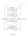
- FIG. 10 illustrates a block diagram of a generalized N-phase harmonic-rejection translational filter including M harmonic-rejection paths according to an embodiment of the present invention.
- the present invention utilizes multiple translational filters to implement a harmonic-rejection filter. These translational filters form multiple signal processing paths with respect to the input signal, respectively, and results of different paths will be combined to obtain a filtered signal. Each of the signal processing paths will provide a specific frequency response for filtering the input signal, and harmonic-mixing products generated in different paths will be substantially reduced.
- FIG. 1 illustrates a block diagram of a translational filter used in a harmonic-rejection filter of the present invention.
- a translational filter 100 includes a switching mixer 110 and an impedance block 120 .
- the switching mixer 110 mixes an input signal S_IN with a local oscillation signal LO.
- the impedance block 120 provides specific baseband impedance in response to all mixing products after mixing switches. This baseband impedance will be translated to input and leads to a symmetric filter response near the LO frequency f LO .
- a filtered signal S_Filtered is therefore generated at the terminal that the input signal S_IN is sent to.
- FIG. 1 illustrates a block diagram of a translational filter used in a harmonic-rejection filter of the present invention.
- a translational filter 100 includes a switching mixer 110 and an impedance block 120 .
- the switching mixer 110 mixes an input signal S_IN with a local oscillation signal LO.
- the impedance block 120 provides specific baseband impedance in response to
- the switching mixer 110 actually includes MOS switches that are driven by multiple phases of local oscillation signal LO. More specifically, the switching mixer 110 in this illustration includes MOS switches that are respectively driven by local oscillation signals LO and LO′ with different phases.
- a conventional switching mixer is usually used for frequency conversion (down or up conversion), and thus its input and output ports are assigned at different nodes of switching mixer (one for RF port and the other for IF port), i.e. switching mixer is connected in series type.
- the purpose of the translational filter is for filtering, it is usually connected at the signal node which needs to be filtered, i.e. its switching mixer is connected in parallel type. In fact, if take signal from RF port of passive switching mixer, it could be have a frequency response like translational loop filter depending on its impedance at IF port.
- FIG. 2 An equivalent model of the translational filer 100 is illustrated in FIG. 2 .
- the principles and operations of the translational filter 100 can be considered as firstly performing a down-conversion operation on the input signal S_IN to translate the input signal S_IN to intermediate frequency accompanied a frequency response in accordance to the baseband impedance block 120 . Then, an up-conversion operation is performed on a result of down-conversion to generate the filtered signal S_Filtered. With the aid of the impedance provided by the impedance block 120 , the translational filter 100 can provide a frequency response over a specific range of frequencies.
- the translational filter 100 is substantially a band-pass filter, and has a frequency response as illustrated on the right hand side of FIG. 2 (having a center frequency at f LO ).
- the switching mixer 110 could be replaced with any other types of mixers, while the impedance block 120 (i.e., impedance block 142 ( 144 )) could include any possible combination of active and/or passive components, such as amplifiers, transconductors, inductors, capacitors, resistors (e.g. C, RC, LC, or RLC).
- the translational filter 100 could be a band-stop filter, a band-pass filter, an all-pass filter or a combination of different filtering shapes in both real and complex domains.
- the impedance block 120 when the impedance block 120 includes an inductor in parallel with a capacitor, the impedance block 120 could have a band-pass frequency response and leads to a double pass-band frequency response on translational filter.
- an active component such as an amplifier or transconductor, to combine with capacitors and resistors can also realize an active inductive component to achieve the same effect.
- the translational filter 100 can be extended to a generalized N-Path filter as shown by FIG. 3A , which contains N identical filter branches and each branch includes a switching mixer and an impedance block 142 .
- Each branch is driven by one of N-phase LO signals LO 1 -LON, these LO signals LO 1 -LON are mutually different in phase.
- Each of switching mixer is comprised of multiple MOS or other-type transistors.
- a switching mixer could be coupled to the ground through an impedance block.
- two switching mixers that are driven by complementary-phases LO signals could share one impedance block without being coupled to the ground.
- an N-path filter can be in the form of either single-ended or differential configuration.
- FIG. 3B illustrates a differential form of an N-path filter according to one embodiment of the present invention.
- the differential N-path filter includes two parts. One part is for positive component S_IN+ of the input signal S_IN, while the other part is for negative component S_IN ⁇ of the input signal S_IN.
- One of the filter branches of the part for positive component share an impedance block with one of the filter branches of the part for negative component, and they are interconnected.
- a switching mixer could be coupled to the ground through an impedance block.
- two switching mixers that are driven by complementary-phases LO signals could share one impedance block without being coupled to the ground.
- a translational filter 200 is implemented by at least four filter branches 210 - 240 as illustrated in FIG. 4 for either single-ended or differential translation filter configurations. For single-ended cases, the number of branches may be reduced by half.
- the four branches 210 , 220 , 230 and 240 are driven by four-phase local oscillation signals such as 0, 90, 180, and 270 degree for LO 1 , LO 2 , LO 3 , and LO 4 , respectively to prevent degradation of the desired signal resulting from signal and noise at the image location on the frequency spectrum.
- the translational filter 200 provides a frequency response based on each of the impedance blocks to filter the input signal S_IN.
- the reference ground of the impedance blocks can be merged to form one differential impedance block.
- two single-ended capacitors, one in 210 and the other in 230 can be combined as one differential capacitor at quarter size.
- a switching mixer could be coupled to the ground through an impedance block.
- two switching mixers that are driven by complementary-phase LO signals e.g. switching mixer driven by LO 1 and LO 3 , LO 2 and LO 4 ) could share one impedance block without being coupled to the ground.
- the N-Phase local oscillation signals LO 1 -LON could be either non-overlapped or overlapped.
- duty-cycle of N-Phase LO is designed to be (100/N) %, however, some specific duty-cycle might be taken for special design requirements, such as harmonic rejection.
- timing charts of the oscillation signals LO 1 -LO 4 are illustrated in FIG. 5 . That is, the local oscillation signals LO 1 -LO 4 could be about either 25% duty-cycle or 50% duty-cycle, and could be overlapped or non-overlapped.
- the translational filter has advantages of High-Q and precisely tunable center frequency, but it suffers from harmonic-mixing problem for wideband applications.
- all undesired signals, interferers, or blockers near harmonics of local oscillation signal at multiples of LO frequency f LO will introduce the undesired harmonic-mixing products to the IF port of switching mixer during the multiplication with harmonics of local oscillation signal, and meanwhile these undesired harmonic-mixing products will be up-converted back to the input port of translational loop filter via the multiplication with the fundamental local oscillation signal.
- the present invention utilizes a harmonic-rejection path to reduce/cancel the harmonic-mixing products generated in a main path. As a result, only mixing result corresponding to the fundamental frequency will be reserved.
- FIG. 6 illustrates a block diagram of a conventional Harmonic-Rejection Mixer (HRM).
- HRM Harmonic-Rejection Mixer
- another harmonic-rejection path is introduced.
- the sum of in-phase and quadrature-phase paths has the square-root of twice in magnitude and negative/positive 45 degree in phase as the dotted line shown on the bottom side of FIG. 6 .
- To take another path driven by 45 degree local oscillation signal and magnified by the square-root of two can ideally cancel out 3 rd -order and 5 th -order harmonic-mixing products.
- the rejection-ratio strongly depends on gain and phase mismatch between three paths.
- FIG. 7A illustrates a schematic diagram of a harmonic-rejection translation filter according to one embodiment of the present invention.
- a harmonic-rejection translation filter 300 includes a main path 310 and a harmonic-rejection path 320 .
- the main path 310 includes a first translation filter 312 while the harmonic-rejection path 320 includes a second translation filter 314 .
- the first translation filter 312 is driven by local oscillation signals LOM 1 -LOM 4 , having the frequency at F LO and phases P 1 -P 4 .
- the second translation filter 314 is driven by local oscillation signals LOH 1 -LOH 4 , having the frequency at F LO and phases P 5 -P 8 .
- a signal combiner 330 combines a first output signal S_F 1 from the main path 310 with a second output signal S_F 2 from the harmonic-rejection path 320 , thereby generating a filtered signal S_Filtered.
- FIG. 7B illustrates the harmonic-rejection translation filter 300 in further details.
- the first translation filter 312 may include identical four filter branches and the filter branches in the first translation filter 312 are driven by the corresponding local oscillation signals LOM 1 -LOM 4 at phases P 1 -P 4 (0, 180, 90 and 270 degree), respectively. As these four filter branches are driven by quadrature-phase local oscillation signals, signal degradation by image can be also prevented.
- the first translation filter 312 provides a frequency response depending on components included in each of the impedance blocks to the input signal S_IN.
- the second translation filter 314 is identical to the first translation filter 312 in the number of the filter branches. And each filter branch of the second translation filter 314 is also identical to the filter branch in the first translation filter 312 .
- the filter branches in the second translation filter 314 are driven by the local oscillation signals LOH 1 -LOH 4 that has phases P 5 -P 8 different to phases P 1 -P 4 of the local oscillation signals LOM 1 -LOM 4 .
- the local oscillation signals LOH 1 -LOH 4 may have the phases P 5 -P 8 at 45, 225, 135 and 315 degree.
- FIG. 8 illustrates equations and corresponding phasor plots of each path with respect to fundamental, 3 rd -order, and 5 th -order harmonic-mixing products. Different to conventional mixer, only in-phase and out-of-phase mixing products will be remained at the output of either main path or harmonic-rejection path due to dual-conversion in a translational filter.
- both the first translation filter 312 of the main path 310 and the second translation filter 314 of the harmonic-rejection path 320 can provide frequency filtering effect to the input signal S_IN, while the second translation filter 314 of the harmonic-rejection path 320 can further provide harmonic-rejection effect to cancel interferences caused by harmonics of the local oscillation signal.
- the first translation filter 312 and the second translation filter 314 may include filter branches of different quantities, For example, each of the first translation filter 312 and the second translation filter 314 may have two, eight or other number of filter branches.
- the harmonic-rejection translational filter 300 can reject 3 rd -order and 5 th -order harmonic-mixing products by means of driving two identical translation filters with the local oscillation signals with eight different phases and combining their respective outputs.
- this may not be enough to reject only 3 rd -order and 5 th -order harmonic-mixing products for some systems, higher-order odd harmonics rejection might be mandatory. Therefore, the present invention further provides a high-order harmonic-rejection translational filter having more translation filters that are driven by the local oscillation signals with more different phases.
- FIG. 9 illustrates a harmonic-rejection translational filter 400 has the capability of rejecting 3 rd -order, 5 th -order, 7 th -order and 9 th -order harmonic-mixing products. In fact, it can achieve all odd harmonics rejection if phase mismatch is good enough.
- the harmonic-rejection translational filter 400 includes a main path 410 , a first harmonic-rejection path 420 , a second harmonic-rejection path 430 and a third harmonic-rejection path 440 . Each of them includes a translation filter that is driven by local oscillation signals with mutually different phases.
- a first translation filter 412 included in the main path 410 is driven by the local oscillation signals LOM 1 -LOM 4
- a second translation filter 414 included in the first harmonic-rejection path 420 is driven by the local oscillation signals LOH 1 _ 1 -LOH 1 _ 4
- a third translation filter 416 included in the second harmonic-rejection path 430 is driven by the local oscillation signals LOH 2 _ 1 -LOH 2 _ 4
- a fourth translation filter 418 included in the third harmonic-rejection path 440 is driven by the local oscillation signals LOH 3 _ 1 -LOH 3 _ 4 .
- the local oscillation signals LOM 1 -LOM 4 LOH 1 _ 1 -LOH 1 _ 4 , LOH 2 _ 1 -LOH 2 _ 4 and LOH 3 _ 1 -LOH 3 _ 4 respectively have same frequency at f LO but mutually different phases.
- the local oscillation signals LOM 1 -LOM 4 could have the phases at 0, 180, 90 and 270 degree
- the local oscillation signals LOH 1 _ 1 -LOH 1 _ 4 could have the phases at 45, 225, 135 and 315 degree
- the local oscillation signals LOH 2 _ 1 -LOH 2 _ 4 could have the phases at 22.5, 202.5, 112.5 and 292.5 degree
- the local oscillation signals LOH 3 _ 1 -LOH 3 _ 4 could have the phases at 67.5, 247.5, 157.5 and 337.5 degree.
- the harmonic-rejection filter 400 can achieve higher-order harmonic-rejection.
- Output signals of main path 410 and harmonic-rejection paths 420 - 440 will be combined by a signal combiner 450 to generate the filtered signal S_Filtered without harmonic-mixing products if there were no mismatch between each path.
- the translation filter of the present invention could be further extended to an N-path filter having N filter branches.
- the present invention further provides a generalized form of the harmonic-rejection filter based on the N-path filter as shown in FIG. 3A and FIG. 3B .
- FIG. 10 illustrates a schematic diagram of a generalized form of the harmonic-rejection filter of the present invention according to one embodiment of the present invention.
- a generalized harmonic-rejection filter 500 includes multiple paths, a main path 510 _ 1 and multiple harmonic-rejection paths 510 _ 2 - 510 _M.
- Each path receives an output of a signal splitter 510 that is generated according to an input signal S_IN and can have different weighting (with adjustable passive or active gain units with respect to the paths).
- a signal combiner 530 combines outputs of all or selected paths to generate a filtered signal S_Filtered by using one signal adder/subtractor or a combination of multiple signal adders and/or signal subtractors, each can also have different weighting.
- Each of the main path 510 _ 1 and the harmonic-rejection paths 510 _ 2 - 510 _M includes a translational filter that has specific filter branches and corresponding local oscillation frequency and phase. These translational filters are basically identical and each of them has N filter branches.
- the translational filter could have architecture as illustrated in FIG. 3A for the input signal S_IN in the single-ended form, or architecture as illustrated in FIG. 3B for the input signal S_IN in the differential form.
- Each of filter branches of the translational filter in main path 510 _ 1 and harmonic-rejection paths 510 _ 2 - 510 _M is driven by a local oscillation signal at a specific phase.
- phases of the local oscillation signals would be mutually different.
- the number “N” may be identical to or different from the number “M”.
- different number of paths and LO phase in conjunction with different weighting signal splitter/combiner can be determined to meet the harmonics cancellation criteria.
- maximum M*N phases of the LO signals could be utilized for driving these translational filters, each of the LO phases could be equal to (360 degree/(M*N))*n (n is the index of the local oscillation signal).
- the path may further include other components.
- at least one of the main path and the harmonic-rejection paths could further include an adjustable gain unit, which can provide different weighting to reduce gain mismatches between different paths.
- the harmonic-rejection translational filter of the present invention can be employed in wideband receivers as an on-chip tracking filter without extra high-Q components (e.g. external capacitors or inductors) as it is has good immunity against the harmonic-mixing problem, and preserves all advantages of translational filter.
- the harmonic-rejection filter of the present invention preserves all advantages of translational filter (e.g. High-Q and precisely tunable center frequency), and also has the capability to reject all unwanted harmonic-mixing products without paying much penalty of chip size and cost.
- the present invention provides an excellent solution to designing a tracking filter in wideband systems for handling components over a wide range of band.
Landscapes
- Engineering & Computer Science (AREA)
- Power Engineering (AREA)
- Physics & Mathematics (AREA)
- Nonlinear Science (AREA)
- Superheterodyne Receivers (AREA)
- Filters And Equalizers (AREA)
- Inductance-Capacitance Distribution Constants And Capacitance-Resistance Oscillators (AREA)
Priority Applications (1)
| Application Number | Priority Date | Filing Date | Title |
|---|---|---|---|
| US15/125,148 US9871487B2 (en) | 2014-03-13 | 2015-03-13 | Harmonic rejection translational filter |
Applications Claiming Priority (3)
| Application Number | Priority Date | Filing Date | Title |
|---|---|---|---|
| US201461952559P | 2014-03-13 | 2014-03-13 | |
| US15/125,148 US9871487B2 (en) | 2014-03-13 | 2015-03-13 | Harmonic rejection translational filter |
| PCT/CN2015/074229 WO2015135507A1 (fr) | 2014-03-13 | 2015-03-13 | Filtre de translation de rejet d'harmonique |
Publications (2)
| Publication Number | Publication Date |
|---|---|
| US20160380593A1 US20160380593A1 (en) | 2016-12-29 |
| US9871487B2 true US9871487B2 (en) | 2018-01-16 |
Family
ID=54070966
Family Applications (1)
| Application Number | Title | Priority Date | Filing Date |
|---|---|---|---|
| US15/125,148 Active US9871487B2 (en) | 2014-03-13 | 2015-03-13 | Harmonic rejection translational filter |
Country Status (4)
| Country | Link |
|---|---|
| US (1) | US9871487B2 (fr) |
| EP (1) | EP3039789B1 (fr) |
| CN (1) | CN105723624B (fr) |
| WO (1) | WO2015135507A1 (fr) |
Cited By (1)
| Publication number | Priority date | Publication date | Assignee | Title |
|---|---|---|---|---|
| US11463071B2 (en) | 2018-04-23 | 2022-10-04 | Samsung Electronics Co,. Ltd | Asymmetrical filtering to improve GNSS performance in presence of wideband interference |
Families Citing this family (8)
| Publication number | Priority date | Publication date | Assignee | Title |
|---|---|---|---|---|
| US9817502B2 (en) * | 2014-12-29 | 2017-11-14 | Synaptics Incorporated | Switched-capacitor harmonic-reject mixer |
| US10171034B2 (en) | 2016-04-08 | 2019-01-01 | Mediatek Inc. | Phase-rotated harmonic-rejection mixer apparatus |
| US10419046B2 (en) | 2016-05-26 | 2019-09-17 | Mediatek Singapore Pte. Ltd | Quadrature transmitter, wireless communication unit, and method for spur suppression |
| US10009050B2 (en) * | 2016-05-26 | 2018-06-26 | Mediatek Singapore Pte. Ltd. | Quadrature transmitter, wireless communication unit, and method for spur suppression |
| CN110945781B (zh) * | 2017-07-20 | 2022-12-27 | 华为技术有限公司 | 具有对称边带增益的单平衡电压模式无源混频器 |
| CN111211737B (zh) * | 2020-03-03 | 2024-05-31 | 芯原微电子(上海)股份有限公司 | 高谐波抑制比混频电路 |
| CN115085744B (zh) * | 2021-03-12 | 2024-07-19 | 瑞昱半导体股份有限公司 | 发射器 |
| WO2023100283A1 (fr) * | 2021-12-01 | 2023-06-08 | 三菱電機株式会社 | Circuit de filtre |
Citations (11)
| Publication number | Priority date | Publication date | Assignee | Title |
|---|---|---|---|---|
| US7409245B1 (en) * | 2007-01-30 | 2008-08-05 | Cardiac Pacemakers, Inc. | Variable antenna matching network for an implantable antenna |
| CN101373950A (zh) | 2007-08-20 | 2009-02-25 | 瑞昱半导体股份有限公司 | 混频装置及相关方法 |
| CN101772886A (zh) | 2007-08-07 | 2010-07-07 | Nxp股份有限公司 | 用于执行谐波抑制混频的谐波抑制混频器单元和方法 |
| CN102106076A (zh) | 2008-06-25 | 2011-06-22 | 西凯渥资讯处理科技公司 | 用于实施谐波抑制混频器的系统及方法 |
| CN102308472A (zh) | 2009-02-04 | 2012-01-04 | Nxp股份有限公司 | 多相谐波抑制混频器 |
| CN102347731A (zh) | 2010-07-21 | 2012-02-08 | 联发科技(新加坡)私人有限公司 | 信号转换装置的谐波抑制与其方法 |
| US20120063555A1 (en) * | 2009-03-17 | 2012-03-15 | Skyworks Solutions, Inc. | Saw-less, lna-less low noise receiver |
| CN102522952A (zh) | 2011-12-30 | 2012-06-27 | 广州市广晟微电子有限公司 | 一种谐波抑制混频器和gsm射频芯片 |
| US20120238232A1 (en) | 2011-03-17 | 2012-09-20 | David Murphy | Method and system for low-noise, highly-linear receiver front-end |
| US8441470B2 (en) * | 2008-01-10 | 2013-05-14 | Konica Minolta Sensing, Inc. | Color sensor unit for use in display device, color measuring device for use in display device, display system incorporated with color sensor unit, and display calibration method |
| US8670739B1 (en) * | 2012-12-13 | 2014-03-11 | Broadcom Corporation | Frequency-translational bandpass filter with harmonic rejection |
-
2015
- 2015-03-13 CN CN201580002578.3A patent/CN105723624B/zh active Active
- 2015-03-13 WO PCT/CN2015/074229 patent/WO2015135507A1/fr not_active Ceased
- 2015-03-13 EP EP15735613.0A patent/EP3039789B1/fr active Active
- 2015-03-13 US US15/125,148 patent/US9871487B2/en active Active
Patent Citations (17)
| Publication number | Priority date | Publication date | Assignee | Title |
|---|---|---|---|---|
| US7409245B1 (en) * | 2007-01-30 | 2008-08-05 | Cardiac Pacemakers, Inc. | Variable antenna matching network for an implantable antenna |
| CN101772886A (zh) | 2007-08-07 | 2010-07-07 | Nxp股份有限公司 | 用于执行谐波抑制混频的谐波抑制混频器单元和方法 |
| US8280333B2 (en) * | 2007-08-07 | 2012-10-02 | Nxp B.V. | Harmonic rejection mixer unit and method for performing a harmonic rejection mixing |
| CN101373950A (zh) | 2007-08-20 | 2009-02-25 | 瑞昱半导体股份有限公司 | 混频装置及相关方法 |
| US8441470B2 (en) * | 2008-01-10 | 2013-05-14 | Konica Minolta Sensing, Inc. | Color sensor unit for use in display device, color measuring device for use in display device, display system incorporated with color sensor unit, and display calibration method |
| US8165538B2 (en) | 2008-06-25 | 2012-04-24 | Skyworks Solutions, Inc. | Systems and methods for implementing a harmonic rejection mixer |
| CN102106076A (zh) | 2008-06-25 | 2011-06-22 | 西凯渥资讯处理科技公司 | 用于实施谐波抑制混频器的系统及方法 |
| CN102308472A (zh) | 2009-02-04 | 2012-01-04 | Nxp股份有限公司 | 多相谐波抑制混频器 |
| US8606210B2 (en) | 2009-02-04 | 2013-12-10 | Nxp, B.V. | Polyphase harmonic rejection mixer |
| CN102428653A (zh) | 2009-03-17 | 2012-04-25 | 天工新技术有限公司 | 无表面声波、无低噪声放大器的低噪声接收器 |
| US20120063555A1 (en) * | 2009-03-17 | 2012-03-15 | Skyworks Solutions, Inc. | Saw-less, lna-less low noise receiver |
| US9071325B2 (en) * | 2009-03-17 | 2015-06-30 | Skyworks Solutions, Inc. | Saw-less, LNA-less low noise receiver |
| CN102347731A (zh) | 2010-07-21 | 2012-02-08 | 联发科技(新加坡)私人有限公司 | 信号转换装置的谐波抑制与其方法 |
| US8552790B2 (en) | 2010-07-21 | 2013-10-08 | Mediatek Singapore Pte. Ltd. | Harmonic rejection of signal converting device and method thereof |
| US20120238232A1 (en) | 2011-03-17 | 2012-09-20 | David Murphy | Method and system for low-noise, highly-linear receiver front-end |
| CN102522952A (zh) | 2011-12-30 | 2012-06-27 | 广州市广晟微电子有限公司 | 一种谐波抑制混频器和gsm射频芯片 |
| US8670739B1 (en) * | 2012-12-13 | 2014-03-11 | Broadcom Corporation | Frequency-translational bandpass filter with harmonic rejection |
Non-Patent Citations (3)
| Title |
|---|
| "International Search Report" dated May 29, 2015 for International application No. PCT/CN2015/074229, International filing date:Mar. 13, 2015. |
| David Murphy et al., "A Blocker-Tolerant, Noise-Cancelling Receiver Suitable for Wideband Wireless Applications", IEEE Journal of Solid-State Circuits, vol. 47, No. 12, Dec. 3, 2012, pp. 2943-2962. |
| David Murphy et al., A Blocker-Tolerant, Noise-Cancelling Receiver Suitable for Wideband Wireless Applications, IEEE Journal of Solid-State Circuits, vol. 47, No. 12, Dec. 2012, pp. 2943-2963, XP011485437, IEEE. |
Cited By (1)
| Publication number | Priority date | Publication date | Assignee | Title |
|---|---|---|---|---|
| US11463071B2 (en) | 2018-04-23 | 2022-10-04 | Samsung Electronics Co,. Ltd | Asymmetrical filtering to improve GNSS performance in presence of wideband interference |
Also Published As
| Publication number | Publication date |
|---|---|
| US20160380593A1 (en) | 2016-12-29 |
| EP3039789A4 (fr) | 2016-12-07 |
| EP3039789B1 (fr) | 2019-03-06 |
| EP3039789A1 (fr) | 2016-07-06 |
| CN105723624A (zh) | 2016-06-29 |
| WO2015135507A1 (fr) | 2015-09-17 |
| CN105723624B (zh) | 2019-06-14 |
Similar Documents
| Publication | Publication Date | Title |
|---|---|---|
| US9871487B2 (en) | Harmonic rejection translational filter | |
| EP3039790B1 (fr) | Filtrage bloqueur pour récepteur à suppression de bruit | |
| JP5670417B2 (ja) | Sawレス、lnaレス低ノイズ受信器 | |
| US8704582B2 (en) | High linearity mixer using a 33% duty cycle clock for unwanted harmonic suppression | |
| US9344124B2 (en) | Jammer resistant noise cancelling receiver front end | |
| JP2012521154A5 (fr) | ||
| US10084433B2 (en) | Feedforward filter using translational filter | |
| JP2010521889A (ja) | 送信信号リーケージの影響を低減するためのノッチ・フィルタを有する無線受信機 | |
| Seo et al. | A passive-mixer-first acoustic-filtering superheterodyne RF front-end | |
| JP7618791B2 (ja) | 受信機回路 | |
| EP2204907A1 (fr) | Amplificateur doté d'un filtre sur puce | |
| CN103348589B (zh) | 频率转换滤波器设备和方法 | |
| US8121577B1 (en) | Controllable input impedance radio frequency mixer | |
| KR101732785B1 (ko) | 믹서에 대한 시스템과 방법 | |
| US9432610B2 (en) | Receiver apparatus, tuner, and circuit | |
| US10158387B1 (en) | Frequency down-converter with high immunity to blocker and method thereof | |
| CN115765772B (zh) | 低功耗混频优先型宽带接收机前端模块 | |
| JP2008067090A (ja) | 周波数変換器 | |
| CN113261208A (zh) | 一种用于载波聚合的射频接收机 | |
| Syu et al. | X-band weaver-hartley low-IF downconverter with a resonant LC load | |
| Phang | On-Chip Image Reject Techniques for Wireless Receivers | |
| JP2006279108A (ja) | 周波数変換方法、周波数変換回路、およそれを搭載した通信システム |
Legal Events
| Date | Code | Title | Description |
|---|---|---|---|
| AS | Assignment |
Owner name: MEDIATEK INC., TAIWAN Free format text: ASSIGNMENT OF ASSIGNORS INTEREST;ASSIGNORS:LU, YING-TSANG;HUNG, CHIH-MING;LEE, MENG-CHANG;SIGNING DATES FROM 20171107 TO 20171120;REEL/FRAME:044220/0520 |
|
| STCF | Information on status: patent grant |
Free format text: PATENTED CASE |
|
| MAFP | Maintenance fee payment |
Free format text: PAYMENT OF MAINTENANCE FEE, 4TH YEAR, LARGE ENTITY (ORIGINAL EVENT CODE: M1551); ENTITY STATUS OF PATENT OWNER: LARGE ENTITY Year of fee payment: 4 |
|
| MAFP | Maintenance fee payment |
Free format text: PAYMENT OF MAINTENANCE FEE, 8TH YEAR, LARGE ENTITY (ORIGINAL EVENT CODE: M1552); ENTITY STATUS OF PATENT OWNER: LARGE ENTITY Year of fee payment: 8 |