US9911532B2 - Forced convection liquid cooling of fluid-filled high density pulsed power capacitor with native fluid - Google Patents
Forced convection liquid cooling of fluid-filled high density pulsed power capacitor with native fluid Download PDFInfo
- Publication number
- US9911532B2 US9911532B2 US14/467,299 US201414467299A US9911532B2 US 9911532 B2 US9911532 B2 US 9911532B2 US 201414467299 A US201414467299 A US 201414467299A US 9911532 B2 US9911532 B2 US 9911532B2
- Authority
- US
- United States
- Prior art keywords
- capacitors
- heat exchanger
- cooling fluid
- passageway
- bank
- Prior art date
- Legal status (The legal status is an assumption and is not a legal conclusion. Google has not performed a legal analysis and makes no representation as to the accuracy of the status listed.)
- Active, expires
Links
Images


Classifications
-
- H—ELECTRICITY
- H01—ELECTRIC ELEMENTS
- H01G—CAPACITORS; CAPACITORS, RECTIFIERS, DETECTORS, SWITCHING DEVICES, LIGHT-SENSITIVE OR TEMPERATURE-SENSITIVE DEVICES OF THE ELECTROLYTIC TYPE
- H01G2/00—Details of capacitors not covered by a single one of groups H01G4/00-H01G11/00
- H01G2/08—Cooling arrangements; Heating arrangements; Ventilating arrangements
-
- H—ELECTRICITY
- H01—ELECTRIC ELEMENTS
- H01G—CAPACITORS; CAPACITORS, RECTIFIERS, DETECTORS, SWITCHING DEVICES, LIGHT-SENSITIVE OR TEMPERATURE-SENSITIVE DEVICES OF THE ELECTROLYTIC TYPE
- H01G2/00—Details of capacitors not covered by a single one of groups H01G4/00-H01G11/00
- H01G2/10—Housing; Encapsulation
- H01G2/106—Fixing the capacitor in a housing
-
- H—ELECTRICITY
- H01—ELECTRIC ELEMENTS
- H01G—CAPACITORS; CAPACITORS, RECTIFIERS, DETECTORS, SWITCHING DEVICES, LIGHT-SENSITIVE OR TEMPERATURE-SENSITIVE DEVICES OF THE ELECTROLYTIC TYPE
- H01G4/00—Fixed capacitors; Processes of their manufacture
- H01G4/38—Multiple capacitors, i.e. structural combinations of fixed capacitors
Definitions
- the present disclosure is directed in general to a high density, fluid-filled, pulsed power capacitor, and more particularly to cooling the capacitor to reduce peak operational temperatures, reduce cool-down time, and maintain operating capacitance under high stress conditions; thereby extending operational time for use
- High density pulsed power capacitors are useful in delivering high power electrical pulses with fast current rise times and short pulse duration.
- a series of pulses may be delivered to a load, which increases the capacitor temperature due to energy storage as each pulse is delivered.
- the rise in temperature is often additive as each pulse is delivered.
- Some capacitors may be liquid cooled.
- conventional liquid cooled capacitors have limited ability to remove sufficient heat or thermal energy from the capacitor, and extended downtimes of hours are still incurred along with unacceptably high dielectric temperatures in high-stress operational conditions.
- a high density capacitor comprises of a housing having a cavity, and a plurality of capacitors forming at least one capacitor bank disposed in the housing cavity.
- the capacitors each have an outer surface, and spacers to introduce spacings between the capacitor outer surfaces.
- a native dielectric fluid is disposed in the cavity, and utilized as a cooling fluid via heat exchanger integrated to the housing.
- a pump is hydraulically coupled to the heat exchanger and is configured to circulate the native dielectric fluid residing in the cavity, through the heat exchanger, through the capacitor spacings and along the outer surface of each of the capacitors to cool the capacitors using forced convection.
- the pump may be physically coupled to the housing.
- Both the first passageway and the second passageway may be formed by a pair of plates, each plate having a plurality of fins configured to create even planar flow of fluid through the respective said passageway.
- Each of the plates may be brazed to each other to create a brazement.
- the plenum openings may be configured to evenly dispense the native cooling fluid across the at least one capacitor bank, having an opening size graduated from one side of the plenum to another side of the plenum.
- the capacitor comprises of a bank of capacitors, and spacers introduced in between the capacitors.
- the spacer configuration may allow fluidic channel creation between the capacitors by maintaining physical separation of the capacitors.
- the spacer construction may have features to allow the absorption of thermal expansion of capacitors and mechanical stresses that are induced due to temperature variations during operation. These spacers may also allow the maintenance of a desired flow orientation of the native fluid in between the spacers. The spacers may also enable a uniform pressure distribution between the capacitors under electrical and mechanical loading.
- the capacitor comprises a first bank of capacitors, and a second bank of capacitors disposed upon the first bank of capacitors, and a spacer disposed between the first bank of capacitors and a second bank of capacitors.
- the spacer configuration may allow maintenance of a primary flow direction, for example, vertical.
- the spacer may be configured to also direct a portion of the native cooling fluid from the heat exchanger laterally between the first bank of capacitors and the second bank of capacitors.
- the spacer may have an interface surface configured to engage a top portion of the first bank of capacitors and a lower portion of the second bank of capacitors. The interface surface is configured to secure the first bank of capacitors with respect to the second bank of capacitors, and dampen any vibration of the first and second banks of capacitors.
- the spacer may have at least one opening configured to pass a portion of the native cooling fluid from the plenum openings in a primary direction, and a deflector configured to route a portion of the native cooling fluid from the plenum openings laterally between the first bank of capacitors and the second bank of capacitors.
- the spacer may be configured to provide turbulent flow of the native cooling fluid between the first bank of capacitors and the second bank of capacitors.
- the capacitors are elongated and have major surfaces extending normal with respect to the heat exchanger, configured such that a portion of the native cooling fluid flows in a column in the spacings between the major surfaces of the capacitors.
- a high density capacitor comprises a housing having a cavity, a plurality of capacitors forming a capacitor bank disposed in the housing cavity, the capacitors each having an outer surface, the capacitor bank having spacings between the capacitor outer surfaces, and a native dielectric fluid disposed in the cavity.
- a heat exchanger is integrated with the housing and has a first passageway configured to communicate the native cooling fluid, a second passageway configured to communicate a secondary fluid, and a thermally conductive member separating the first passageway from the second passageway.
- a pump is configured to circulate the native cooling fluid from the cavity, through the heat exchanger first passageway, through the spacings and along the outer surface of each of the capacitors to cool the capacitors using forced convection.
- the second passageway is configured such that the secondary fluid flowing through the second passageway is configured to draw heat from the native cooling fluid flowing through the first passageway.
- the heat exchanger has a plenum having a plurality of openings configured to dispense the native cooling fluid from the heat exchanger first passageway proximate the capacitor bank.
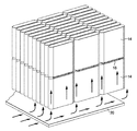
- FIG. 1 illustrates an isometric view of a fluid-filled high density pulsed power capacitor with native fluid having forced convection liquid cooling features
- FIG. 2 illustrates the native cooling fluid flowing from the heat exchanger upwardly between the capacitors in a columnar flow pattern
- FIG. 5 illustrates a cross sectional view of a heat exchanger having the native cooling fluid flowing from the heat exchanger primary fluid inlet in a planar cavity to the fluid openings, and the secondary cooling fluid flowing in a planar cavity thereunder to thermally exchange heat;
- FIG. 6 illustrates the native cooling fluid fin section and the secondary cooling fluid fin section
- FIG. 7 illustrates the cover plate brazed to the top of the native cooling fluid fin section
- FIG. 8 illustrates the diffuser plate brazed to the top of the heat exchanger that forms a pressurized plenum
- FIG. 10 illustrates the spacer members extending between the capacitors
- FIG. 12 illustrates the theoretical means of thermal enhancements using forced convection
- FIG. 13 illustrates the temperature profile at various locations in the capacitor over time during pulsed energy delivery in one embodiment.
- each capacitor 14 formed as coiled capacitor winding.
- the capacitors 14 are shown as having a generally planar form factor, vertically oriented with respect to the base, but they may have a cylindrical form factor or other configuration as desired.
- Each capacitor 14 has a dielectric, such as comprised of polypropylene.
- each capacitor 14 may have a thickness of about 5.3 micrometers and a length of about 320 meters per roll.
- the banks of capacitors 14 may be configured in layers, with a non-metallic spacer plate 16 laterally extending between each layer as shown.
- the housing cavity 13 is filled with a native cooling fluid 18 configured to be both circulated about the exterior surfaces of each of the capacitors 14 to remove heat or thermal energy therefrom, and also release this heat or thermal energy via a heat exchanger 20 that is coupled to and forms a portion of the base of housing 12 as will be discussed below.
- the native cooling fluid 18 may be comprised, but is not limited to, vegetable oil, ester-based oils, or NOVEC fluids manufactured and trademarked by 3M CORPORATION of St. Paul, Minn.
- the capacitor 10 is seen to include a low profile submersible pump 22 secured to and sealed through an end wall 24 of housing 12 .
- the pump 22 is configured to draw the native cooling fluid 18 in housing cavity 13 via an input passageway 26 and associated opening in a manifold 28 to a top portion of the cavity 13 above the banks of capacitors 14 .
- the pump 22 is configured to circulate and deliver the native cooling fluid 18 to a planar upper portion 30 of the heat exchanger 20 via an output passageway 32 , forcing the native cooling fluid 18 to circulate into cavity 13 and between and about each capacitor 14 to create forced convection cooling, as graphically shown by the arrows in FIG. 2 .
- the heated native cooling fluid returns to the manifold 28 and pump 22 as shown in FIG. 3 .
- the heat exchanger 20 also comprises a planar lower portion 34 having input/output ports 36 configured to inject/remove a secondary cooling fluid 38 therein.
- the upper portion 30 and lower portion 34 of heat exchanger 20 are physically isolated from each other, but share a common thermally conductive plate 40 disposed therebetween to facilitate heat or thermal energy exchange between the native cooling fluid 18 and the secondary cooling fluid 38 ( FIG. 5 ) as will be described below.
- the secondary cooling fluid 38 has a lower temperature than the heated native cooling fluid 18 and thus draws heat or thermal energy therefrom.
- Each of the capacitors 14 are spaced from one another by spacer strips 42 as will be discussed shortly.
- FIG. 4 illustrates a top perspective view of the heat exchanger 20 , showing the upper portion 30 having a diffuser plate 50 .
- the heat exchanger 20 comprises an integrated native fluid discharge plenum, including the diffuser plate 50 and having a fluid inlet 52 configured to receive the native cooling fluid 18 from the output passageway 32 .
- the diffuser plate 50 has a plurality of outlet openings 54 with graduated opening sizes configured to discharge the native cooling fluid 18 from the upper portion 30 .
- the native cooling fluid 18 is slightly pressurized, and the graduated outlet openings 54 have varying slot geometry, and in combination with the plenum shape provide application specific fluid flow uniformity to the bottom of the bank of capacitors 14 .
- the heat exchanger 20 has an extremely planar and compact design.
- the upper portion 30 may have a height of 0.75 inches and the lower portion 34 may have a height of 0.5 inches, where the heat exchanger 20 has a length of 30 inches and a width of 18 inches.
- FIG. 5 illustrates a cross sectional view of the flow of the native cooling fluid 18 flowing from the primary fluid inlet 52 ( FIG. 4 ) in a planar passageway 60 having longitudinally extending fins 82 ( FIG. 6 ) formed between a thermally conductive cover plate 64 and the lower portion 34 .
- the flow of the native cooling fluid 18 wraps above to an upper planar cavity 66 forming part of the passageway 60 at portion 68 .
- the cavity 66 is formed between the cover plate 64 and the diffuser plate 50 , and the native fluid flow is discharged through the graduated outlet openings 54 .
- a lower second passageway 70 in the heat exchanger 20 admits the secondary cooling fluid 38 flowing through ports 36 and below the first passageway 60 ; and the secondary cooling fluid 38 is configured to exchange heat with the native cooling fluid 18 flowing through passageway 60 .
- the secondary cooling fluid 38 has a lower temperature than the native cooling fluid 18 flowing through passageway 60 , and thus the secondary cooling fluid 38 draws heat from the native cooling fluid 18 to cool the native cooling fluid 18 to help remove heat or thermal energy transferred by the capacitors 14 into the native cooling fluid 18 .
- FIG. 6 and FIG. 7 show the lower portion 34 comprised of a planar coolant fin section 72 having the longitudinally extending fins 62 spaced from one another to create fluid flow channels therebetween in passageway 70 , as shown in FIG. 5 .
- the fins 62 are configured to provide planar flow of the secondary cooling fluid 38 in passageway 70 and to increase the rate of heat or thermal energy exchange to the secondary cooling fluid 38 in fin section 72 .
- the ports 36 inject and remove the secondary cooling fluid 38 into and from the lower portion 34 .
- One port 36 injects the secondary cooling fluid 38 , while the secondary cooling fluid is drawn out of the other port 36 in a constantly running loop.
- the upper portion 30 comprises a planar coolant fin section 80 brazed to the cover plate 64 , marked in FIG. 7 , to form a brazement.
- the fin section 80 has longitudinally extending fins 82 spaced from one another to create planar fluid flow channels in passageway 60 .
- the fin section 80 is brazed to a top portion of the fin section 72 at the bottom to maximize heat transfer between the secondary cooling fluid 38 and the native cooling fluid 18 , and hydraulically isolate the cooling fluids from each other.
- the fin section 80 is seen to have a tapered fluid injection opening 84 communicating the native cooling fluid 18 from the primary fluid inlet 52 to the channels defined between the fins 82 .
- FIG. 7 illustrates the cover plate 64 brazed to the top of the fin section 80 to form part of the brazement.
- the cover plate 64 does not cover the region 68 defined where the native cooling fluid 18 wraps around the edge of the cover plate 64 to cavity 66 , as previously discussed and shown in FIG. 5 .
- FIG. 8 illustrates the diffuser plate 50 brazed to the upper portion of upper portion 30 above the cover plate 64 to form the discharge plenum comprising planar cavity 66 and openings 54 , as also shown in FIG. 5 .
- the diffuser plate 50 forms part of the brazement.
- FIG. 9 illustrates an exploded view of the spacer plate 16 comprising an interface interposed between the upper bank and the lower bank of capacitors 14 .
- Spacer plate 16 is configured to vertically and laterally direct flow of the native cooling fluid 18 , and also provides simultaneous shock and vibration isolation between the banks of capacitors 14 .
- the spacer plate 16 includes strategic features including cutouts 90 to help maintain primary flow orientation of the native cooling fluid 18 from top to bottom in columns.
- the flow directors 92 are configured in an orientation enabling lateral fluid flow between the banks of capacitors with 3D flow mixing and increased turbulence to enhance thermal transport of the heat drawn from each of the capacitors 14 by convection.
- the flow directors 92 also serve the purpose of separating the ends of the opposing ends of capacitors 14 , and also provide vibration isolation.
- Each flow director 92 of the spacer plate 16 is seen to include a plurality of linearly arranged spacers 94 secured to the upper surface and the lower surface of the respective flow director 92 .
- the lower spacers 94 have lower surfaces 96 configured to engage the upper ends of the lower bank of capacitors 14
- the upper spacers 94 have upper surfaces 96 configured to engage the lower ends of the upper bank of capacitors 14 .
- There is a spacer 94 for each capacitor 14 and each spacer 94 may be comprised of a resilient or slightly resilient material.
- the spacers 94 have fluid channels 98 defined therebetween, permitting lateral flow of a portion of the native cooling fluid 18 across planar portion 100 of the flow director 92 underneath and above the ends of capacitors 14 to cool the end portions of the capacitors 14 .
- FIG. 10 illustrates a plurality of non-metallic integrated spacer strips 102 extending laterally between each of the capacitors 14 , one spacer strip 102 extending along the top portion of a given bank of capacitors 14 , one spacer strip 102 extending along the middle of the same bank of capacitors 14 , and one spacer strip 102 extending along the lower portion of the bank of capacitors 14 .
- the construction of the spacer strips 102 enables columnar fluid routing channels when placed against the major lateral surfaces of the capacitors 14 . Cooler fluid forced through the heat exchanger 20 is admitted into the routing channels provided by the spacer strips 102 and against the lateral surfaces of capacitors 14 to provide cooling.
- Cutouts 90 in spacer plate 16 ensure the distribution of the cooling fluid to multiple banks of the spacer strips 102 , as may be necessitated by multiple banks of capacitors.
- the integrated spacer strips 102 are spring-like secondary spacers that help create spacings between the major side surfaces of the capacitors 14 , allowing the lateral major surfaces of the capacitors to be cooled while helping maintain a compressive preload between the capacitors 14 over a range of temperature operation, absorbing temperature-induced stresses and deformations.
- This cooling design is scalable and can be easily tailored to a variety of winding configurations and capacitor form factors.
- FIG. 11A illustrates the spacer strips 102 interposed between the capacitors 14 .
- FIG. 11B illustrates each spacer strip 102 has overlapping solid trapezoidal sections 104 creating fluid routing channels 106 on each side of the spacer strips 102 when placed against the lateral surfaces of capacitors 14 to facilitate the vertical flow of the native cooling fluid 18 .
- the overlapping sections 104 and the gaps created by them provide the spring-like compressive preload between the capacitors 14 .
- FIG. 12 graphically illustrates the mechanisms of thermal enhancements according to this disclosure.
- the utilization of active liquid-to-coolant heat exchanger 20 with pump flow limits native fluid temperature rise or its stagnation.
- the lateral surface areas of the capacitors 14 are transformed from dead zones to being active.
- the spring-like spacer strips 102 help utilize the lateral surface area efficiency with forced flow.
- the flow director 92 configuration further enhances heat transfer by introducing lateral flow to cool the top surface of the bottom capacitor bank and bottom surface of the top capacitor bank. Similar purpose is served by the fluid sweep enabled by manifold 28 at the top of the top capacitor bank.
- the top and the bottom surface areas of the capacitors 14 are thus better utilized, where the forced flow of native cooling fluid 18 provides an improved heat transfer coefficient.
- the flow directors 92 of the spacer plate 16 , the spacer strips 102 and other features further enhance heat transfer.
- FIG. 13 illustrates a graph of temperature profile during continuous delivery of energy pulses, such as 20 pulses per minute pulse cycle (every 3 seconds), with a 30 minute pause between pulse cycles, with a maximum capacitor temperature of about 40 degrees Celsius.
- a continuous delivery of energy pulses is possible, without any rest time between energy pulse cycles, as the capacitor 10 cooling system maintains the temperature of the capacitors approximately 15 degrees Celsius below a maximum operating temperature, such as 55 degrees Celsius for certain polypropylene capacitor dielectrics.
- This profile provides a long capacitor life, enabling a higher voltage capacitor per module, and a higher energy density capacitor. This also allows a greater flexibility in polypropylene choices for the capacitors 14 , and providing a substantially increased MJ/cubic meter. Further, this prevents degradation in capacitor performance during all stages of operation.
- the thermal scheme enables performance independent of the capacitor orientation with respect to gravity.
- the low profile heat exchanger has an integrated plenum-fed distributor.
- the heat exchanger, spacer plate and spacer strips enable uniform fluid flow of the native cooling fluid to the entire capacitor bank.
- the heat exchanger heat transfer area is scalable as required.
Landscapes
- Engineering & Computer Science (AREA)
- Power Engineering (AREA)
- Microelectronics & Electronic Packaging (AREA)
- Manufacturing & Machinery (AREA)
- Cooling Or The Like Of Electrical Apparatus (AREA)
Priority Applications (4)
| Application Number | Priority Date | Filing Date | Title |
|---|---|---|---|
| US14/467,299 US9911532B2 (en) | 2014-08-25 | 2014-08-25 | Forced convection liquid cooling of fluid-filled high density pulsed power capacitor with native fluid |
| PL15738788T PL3186813T3 (pl) | 2014-08-25 | 2015-06-24 | Chłodzenie cieczą z wymuszoną konwekcją wypełnionego płynem, impulsowego kondensatora mocy o dużej gęstości z płynem wewnętrznym |
| PCT/US2015/037507 WO2016032606A1 (en) | 2014-08-25 | 2015-06-24 | Forced convection liquid cooling of fluid-filled high density pulsed power capacitor with native fluid |
| EP15738788.7A EP3186813B1 (en) | 2014-08-25 | 2015-06-24 | Forced convection liquid cooling of fluid-filled high density pulsed power capacitor with native fluid |
Applications Claiming Priority (1)
| Application Number | Priority Date | Filing Date | Title |
|---|---|---|---|
| US14/467,299 US9911532B2 (en) | 2014-08-25 | 2014-08-25 | Forced convection liquid cooling of fluid-filled high density pulsed power capacitor with native fluid |
Publications (2)
| Publication Number | Publication Date |
|---|---|
| US20160055971A1 US20160055971A1 (en) | 2016-02-25 |
| US9911532B2 true US9911532B2 (en) | 2018-03-06 |
Family
ID=53673299
Family Applications (1)
| Application Number | Title | Priority Date | Filing Date |
|---|---|---|---|
| US14/467,299 Active 2035-07-18 US9911532B2 (en) | 2014-08-25 | 2014-08-25 | Forced convection liquid cooling of fluid-filled high density pulsed power capacitor with native fluid |
Country Status (4)
| Country | Link |
|---|---|
| US (1) | US9911532B2 (pl) |
| EP (1) | EP3186813B1 (pl) |
| PL (1) | PL3186813T3 (pl) |
| WO (1) | WO2016032606A1 (pl) |
Cited By (3)
| Publication number | Priority date | Publication date | Assignee | Title |
|---|---|---|---|---|
| US11621125B2 (en) * | 2017-04-13 | 2023-04-04 | Comet Ag | Variable vacuum capacitor and cooling method |
| US11632021B2 (en) | 2021-04-05 | 2023-04-18 | Raytheon Company | Dynamo-electric machine |
| US11742661B2 (en) | 2020-10-16 | 2023-08-29 | Raytheon Company | Augmented bus impedance and thump control for electrical power systems |
Families Citing this family (1)
| Publication number | Priority date | Publication date | Assignee | Title |
|---|---|---|---|---|
| WO2018004765A2 (en) | 2016-04-01 | 2018-01-04 | Raytheon Company | Hybrid energy storage modules for pulsed power effectors with medium voltage direct current (mvdc) power distribution |
Citations (67)
| Publication number | Priority date | Publication date | Assignee | Title |
|---|---|---|---|---|
| GB167916A (en) | 1920-06-12 | 1921-08-25 | Giulio Schroeder | Improvements in electrical transformers |
| US1646823A (en) | 1925-09-28 | 1927-10-25 | Gen Electric | Regulation of dynamo-electric machines |
| US2149082A (en) | 1937-10-29 | 1939-02-28 | Gen Electric | Electric circuit |
| US2740510A (en) | 1952-12-19 | 1956-04-03 | Western Electric Co | Acceleration and deceleration control for machines |
| US3004381A (en) | 1956-04-06 | 1961-10-17 | Jr Edmund O Schweitzer | Electrical system |
| US3024298A (en) | 1958-07-10 | 1962-03-06 | Raytheon Co | Evaporative-gravity cooling systems |
| US3043000A (en) | 1958-04-24 | 1962-07-10 | Mc Graw Edison Co | Method of forming a conductive coil on a closed magnetic core |
| US3183431A (en) | 1961-01-23 | 1965-05-11 | Sundstrand Corp | Constant frequency brushless generating system |
| US3187250A (en) | 1961-09-11 | 1965-06-01 | American Brake Shoe Co | Frequency control system for a. c. generating apparatus |
| US3315148A (en) | 1963-10-31 | 1967-04-18 | Gen Precision Inc | A.-c. generator power supply |
| US3452229A (en) | 1966-09-16 | 1969-06-24 | John Rex Pimlott | Modular inductor alternator |
| US3571693A (en) | 1968-11-21 | 1971-03-23 | Nasa | Constant frequency output two-stage induction machine systems |
| US3667012A (en) | 1970-07-31 | 1972-05-30 | Westinghouse Electric Corp | Electrical apparatus with frequency controlled load compensation |
| US4001666A (en) | 1975-04-03 | 1977-01-04 | General Electric Company | Load peak shaver power regulating system |
| US4011535A (en) | 1976-07-09 | 1977-03-08 | General Electric Company | Vaporization cooled transformer |
| US4048603A (en) | 1976-12-27 | 1977-09-13 | General Electric Company | Vaporization cooled transformer |
| EP0033697A2 (fr) | 1980-02-05 | 1981-08-12 | L.C.C.-C.I.C.E. - Compagnie Europeenne De Composants Electroniques | Condensateur multi-éléments à haute dissipation thermique |
| US4393964A (en) | 1979-03-23 | 1983-07-19 | Ipanema Company | Hybrid power system and method for operating same |
| US4439720A (en) | 1981-01-23 | 1984-03-27 | Societe Aman | Units for generating constant-frequency alternating electric energy with substitute driving means |
| US4444444A (en) | 1981-08-17 | 1984-04-24 | Societe Nationale Industrielle Aerospatiale | Equipment for storage of energy under kinetic form and recovery thereof in electric form and method of using such equipment |
| EP0124809A1 (de) | 1983-05-10 | 1984-11-14 | BBC Aktiengesellschaft Brown, Boveri & Cie. | Induktives Bauelement |
| US4612494A (en) | 1984-01-18 | 1986-09-16 | Mitsubishi Denki Kabushiki Kaisha | Flywheel energy storage system |
| US4623771A (en) | 1984-06-19 | 1986-11-18 | Sharp Kabushiki Kaisha | High-voltage transformer cooling assembly of microwave oven |
| US4926107A (en) | 1986-07-31 | 1990-05-15 | The Boeing Company | Variable inertia energy storage system |
| US4947287A (en) | 1988-11-30 | 1990-08-07 | Sundstrand Corporation | Capacitor cooling arrangement |
| US4971522A (en) | 1989-05-11 | 1990-11-20 | Butlin Duncan M | Control system and method for AC motor driven cyclic load |
| US5097194A (en) | 1990-09-12 | 1992-03-17 | Randal Walton | Motor with plural generators set |
| US5508672A (en) | 1993-03-19 | 1996-04-16 | Mitsubishi Denki Kabushiki Kaisha | Stationary induction apparatus |
| US5545966A (en) | 1994-04-29 | 1996-08-13 | Delco Electronics Corp. | Air/liquid cooled metallic turn for high frequency high power charging transformers |
| US5646458A (en) | 1996-02-22 | 1997-07-08 | Atlas Energy Systems, Inc. | Uninterruptible power system with a flywheel-driven source of standby power |
| US5660749A (en) | 1994-02-14 | 1997-08-26 | Yashima Electric Co., Ltd. | Transformer and A.C. arc welder |
| EP0849170A1 (en) | 1996-12-02 | 1998-06-24 | TRW Inc. | System and method for reducing mechanical disturbances from energy storage flywheels |
| US5808535A (en) | 1996-11-27 | 1998-09-15 | L. C. Miller Company | High frequency water cooled induction heating transformer |
| US6023152A (en) | 1997-04-14 | 2000-02-08 | Piller-Gmbh | System for stabilizing a power supply system |
| US6078119A (en) | 1997-11-26 | 2000-06-20 | Ebara Corporation | Bearingless rotary machine |
| US6239513B1 (en) | 2000-02-24 | 2001-05-29 | Design Power Solutions International | Emergency supplemental power supply for outage protection of critical electric loads |
| US6384703B1 (en) | 2000-12-11 | 2002-05-07 | General Motors Corporation | Fully immersed magnetic transformer with multiple condensing surfaces and method |
| US6573626B1 (en) | 1999-10-08 | 2003-06-03 | Piller Gmbh | Apparatus for uninterruptedly supplying power including an electrical machine and a flywheel |
| US20030231094A1 (en) | 2002-06-12 | 2003-12-18 | Netec Ag | Electromagnetic inductor and transformer device and method of making the same |
| US6710579B2 (en) | 2000-09-27 | 2004-03-23 | Daimlerchrysler Ag | Starter-generator device for internal combustion engines and method for operating the device |
| US20050012395A1 (en) | 2002-12-06 | 2005-01-20 | Steven Eckroad | Integrated closed loop control method and apparatus for combined uninterruptible power supply and generator system |
| US6885268B2 (en) | 2002-04-23 | 2005-04-26 | Puretec Co., Ltd. | Method and device for cooling high voltage transformer for microwave oven |
| US7002443B2 (en) | 2003-06-25 | 2006-02-21 | Cymer, Inc. | Method and apparatus for cooling magnetic circuit elements |
| US7142085B2 (en) | 2002-10-18 | 2006-11-28 | Astec International Limited | Insulation and integrated heat sink for high frequency, low output voltage toroidal inductors and transformers |
| US20070163765A1 (en) * | 2003-10-31 | 2007-07-19 | Patrick Rondier | Power-electronic-cooling device |
| US20080103632A1 (en) | 2006-10-27 | 2008-05-01 | Direct Drive Systems, Inc. | Electromechanical energy conversion systems |
| US7489226B1 (en) | 2008-05-09 | 2009-02-10 | Raytheon Company | Fabrication method and structure for embedded core transformers |
| US20090134705A1 (en) | 2003-06-06 | 2009-05-28 | Claude Michael Kalev | Mbackup flywheel power supply |
| US7663328B2 (en) | 2007-12-12 | 2010-02-16 | The Boeing Company | Multi-phase, multi-frequency controller |
| US20100134940A1 (en) * | 2008-12-23 | 2010-06-03 | Ise Corporation | Hybrid Vehicle Propulsion Energy Storage System |
| US20110084568A1 (en) | 2009-09-30 | 2011-04-14 | Converteam Technology Ltd. | Rotor for electric motor optimized for high power |
| US8009004B2 (en) | 2007-06-27 | 2011-08-30 | Rockwell Automation Technologies, Inc. | Electric coil and core cooling method and apparatus |
| US20120050992A1 (en) * | 2010-08-27 | 2012-03-01 | Sumsung Electro-Mechanics Co., Ltd. | Supercapacitor module |
| US20120075047A1 (en) | 2009-05-16 | 2012-03-29 | Abb Technology Ag | Transformer core |
| US20120187922A1 (en) | 2009-06-15 | 2012-07-26 | Dubois Maxime R | Energy storage system and method |
| US20120286523A1 (en) | 2011-05-10 | 2012-11-15 | The Boeing Company | Reconfigurable stators |
| US20130020893A1 (en) | 2011-01-19 | 2013-01-24 | Converteam Technology Ltd. | Electrical Machines |
| US8373970B2 (en) | 2008-03-20 | 2013-02-12 | Celem Passive Components Ltd. | Sideways conduction cooled high-power capacitor |
| US20130127391A1 (en) | 2010-03-17 | 2013-05-23 | GE ENERGY POWER CONVERSION TECHNOLOGY LTD. (formerly Converteam Technology Ltd.) | Electrical machines |
| US20130261001A1 (en) | 2012-04-03 | 2013-10-03 | The Boeing Company | Nested-rotor open-core flywheel |
| US20130257186A1 (en) | 2012-04-03 | 2013-10-03 | The Boeing Company | Flexible Magnet Directional Stiffening Methods |
| US20130260999A1 (en) | 2012-04-03 | 2013-10-03 | The Boeing Company | Open-core flywheel architecture |
| US20130285491A1 (en) | 2012-04-27 | 2013-10-31 | Raytheon Company | Electro-mechanical kinetic energy storage device and method of operation |
| US20140132380A1 (en) | 2012-11-13 | 2014-05-15 | Raytheon Company | Apparatus and method for thermal management of magnetic devices |
| US20140346868A1 (en) | 2013-05-24 | 2014-11-27 | Raytheon Company | Energy transfer and storage apparatus for delivery of pulsed power |
| US20150288271A1 (en) | 2014-04-04 | 2015-10-08 | Raytheon Company | Inertial energy storage system and hydro-fluoro-ether power transformer scheme for radar power systems and large pfn charging |
| US9306386B2 (en) | 2013-09-13 | 2016-04-05 | Raytheon Company | Electromagnetic DC pulse power system including integrated fault limiter |
Family Cites Families (5)
| Publication number | Priority date | Publication date | Assignee | Title |
|---|---|---|---|---|
| US20070020513A1 (en) * | 2001-10-04 | 2007-01-25 | Ise Corporation | Energy Storage Cell Support Separator and Cooling System for a Multiple Cell Module |
| DE102010013033A1 (de) * | 2010-03-26 | 2011-09-29 | Daimler Ag | Vorrichtung zur Kühlung einer Energiespeichereinrichtung |
| WO2011149868A1 (en) * | 2010-05-24 | 2011-12-01 | Parker-Hannifin Corporation | Cooling system and method |
| FR2966288B1 (fr) * | 2010-10-19 | 2013-03-29 | Commissariat Energie Atomique | Batterie d'une motorisation electrique de vehicule automobile |
| DE102012020516A1 (de) * | 2011-12-09 | 2013-06-13 | W.E.T. Automotive Systems Ag | Temperier-Einrichtung für eine elektrochemische Spannungsquelle |
-
2014
- 2014-08-25 US US14/467,299 patent/US9911532B2/en active Active
-
2015
- 2015-06-24 WO PCT/US2015/037507 patent/WO2016032606A1/en not_active Ceased
- 2015-06-24 PL PL15738788T patent/PL3186813T3/pl unknown
- 2015-06-24 EP EP15738788.7A patent/EP3186813B1/en active Active
Patent Citations (69)
| Publication number | Priority date | Publication date | Assignee | Title |
|---|---|---|---|---|
| GB167916A (en) | 1920-06-12 | 1921-08-25 | Giulio Schroeder | Improvements in electrical transformers |
| US1646823A (en) | 1925-09-28 | 1927-10-25 | Gen Electric | Regulation of dynamo-electric machines |
| US2149082A (en) | 1937-10-29 | 1939-02-28 | Gen Electric | Electric circuit |
| US2740510A (en) | 1952-12-19 | 1956-04-03 | Western Electric Co | Acceleration and deceleration control for machines |
| US3004381A (en) | 1956-04-06 | 1961-10-17 | Jr Edmund O Schweitzer | Electrical system |
| US3043000A (en) | 1958-04-24 | 1962-07-10 | Mc Graw Edison Co | Method of forming a conductive coil on a closed magnetic core |
| US3024298A (en) | 1958-07-10 | 1962-03-06 | Raytheon Co | Evaporative-gravity cooling systems |
| US3183431A (en) | 1961-01-23 | 1965-05-11 | Sundstrand Corp | Constant frequency brushless generating system |
| US3187250A (en) | 1961-09-11 | 1965-06-01 | American Brake Shoe Co | Frequency control system for a. c. generating apparatus |
| US3315148A (en) | 1963-10-31 | 1967-04-18 | Gen Precision Inc | A.-c. generator power supply |
| US3452229A (en) | 1966-09-16 | 1969-06-24 | John Rex Pimlott | Modular inductor alternator |
| US3571693A (en) | 1968-11-21 | 1971-03-23 | Nasa | Constant frequency output two-stage induction machine systems |
| US3667012A (en) | 1970-07-31 | 1972-05-30 | Westinghouse Electric Corp | Electrical apparatus with frequency controlled load compensation |
| US4001666A (en) | 1975-04-03 | 1977-01-04 | General Electric Company | Load peak shaver power regulating system |
| US4011535A (en) | 1976-07-09 | 1977-03-08 | General Electric Company | Vaporization cooled transformer |
| US4048603A (en) | 1976-12-27 | 1977-09-13 | General Electric Company | Vaporization cooled transformer |
| US4393964A (en) | 1979-03-23 | 1983-07-19 | Ipanema Company | Hybrid power system and method for operating same |
| EP0033697A2 (fr) | 1980-02-05 | 1981-08-12 | L.C.C.-C.I.C.E. - Compagnie Europeenne De Composants Electroniques | Condensateur multi-éléments à haute dissipation thermique |
| US4439720A (en) | 1981-01-23 | 1984-03-27 | Societe Aman | Units for generating constant-frequency alternating electric energy with substitute driving means |
| US4444444A (en) | 1981-08-17 | 1984-04-24 | Societe Nationale Industrielle Aerospatiale | Equipment for storage of energy under kinetic form and recovery thereof in electric form and method of using such equipment |
| EP0124809A1 (de) | 1983-05-10 | 1984-11-14 | BBC Aktiengesellschaft Brown, Boveri & Cie. | Induktives Bauelement |
| US4612494A (en) | 1984-01-18 | 1986-09-16 | Mitsubishi Denki Kabushiki Kaisha | Flywheel energy storage system |
| US4623771A (en) | 1984-06-19 | 1986-11-18 | Sharp Kabushiki Kaisha | High-voltage transformer cooling assembly of microwave oven |
| US4926107A (en) | 1986-07-31 | 1990-05-15 | The Boeing Company | Variable inertia energy storage system |
| US4947287A (en) | 1988-11-30 | 1990-08-07 | Sundstrand Corporation | Capacitor cooling arrangement |
| US4971522A (en) | 1989-05-11 | 1990-11-20 | Butlin Duncan M | Control system and method for AC motor driven cyclic load |
| US5097194A (en) | 1990-09-12 | 1992-03-17 | Randal Walton | Motor with plural generators set |
| US5508672A (en) | 1993-03-19 | 1996-04-16 | Mitsubishi Denki Kabushiki Kaisha | Stationary induction apparatus |
| US5660749A (en) | 1994-02-14 | 1997-08-26 | Yashima Electric Co., Ltd. | Transformer and A.C. arc welder |
| US5545966A (en) | 1994-04-29 | 1996-08-13 | Delco Electronics Corp. | Air/liquid cooled metallic turn for high frequency high power charging transformers |
| US5646458A (en) | 1996-02-22 | 1997-07-08 | Atlas Energy Systems, Inc. | Uninterruptible power system with a flywheel-driven source of standby power |
| US5808535A (en) | 1996-11-27 | 1998-09-15 | L. C. Miller Company | High frequency water cooled induction heating transformer |
| EP0849170A1 (en) | 1996-12-02 | 1998-06-24 | TRW Inc. | System and method for reducing mechanical disturbances from energy storage flywheels |
| US5921505A (en) | 1996-12-02 | 1999-07-13 | Trw Inc. | System and method for reducing mechanical disturbances from energy storage flywheels |
| US6023152A (en) | 1997-04-14 | 2000-02-08 | Piller-Gmbh | System for stabilizing a power supply system |
| US6078119A (en) | 1997-11-26 | 2000-06-20 | Ebara Corporation | Bearingless rotary machine |
| US6573626B1 (en) | 1999-10-08 | 2003-06-03 | Piller Gmbh | Apparatus for uninterruptedly supplying power including an electrical machine and a flywheel |
| US6239513B1 (en) | 2000-02-24 | 2001-05-29 | Design Power Solutions International | Emergency supplemental power supply for outage protection of critical electric loads |
| US6710579B2 (en) | 2000-09-27 | 2004-03-23 | Daimlerchrysler Ag | Starter-generator device for internal combustion engines and method for operating the device |
| US6384703B1 (en) | 2000-12-11 | 2002-05-07 | General Motors Corporation | Fully immersed magnetic transformer with multiple condensing surfaces and method |
| US6885268B2 (en) | 2002-04-23 | 2005-04-26 | Puretec Co., Ltd. | Method and device for cooling high voltage transformer for microwave oven |
| US20030231094A1 (en) | 2002-06-12 | 2003-12-18 | Netec Ag | Electromagnetic inductor and transformer device and method of making the same |
| US7142085B2 (en) | 2002-10-18 | 2006-11-28 | Astec International Limited | Insulation and integrated heat sink for high frequency, low output voltage toroidal inductors and transformers |
| US20050012395A1 (en) | 2002-12-06 | 2005-01-20 | Steven Eckroad | Integrated closed loop control method and apparatus for combined uninterruptible power supply and generator system |
| US20090134705A1 (en) | 2003-06-06 | 2009-05-28 | Claude Michael Kalev | Mbackup flywheel power supply |
| US7002443B2 (en) | 2003-06-25 | 2006-02-21 | Cymer, Inc. | Method and apparatus for cooling magnetic circuit elements |
| US20070163765A1 (en) * | 2003-10-31 | 2007-07-19 | Patrick Rondier | Power-electronic-cooling device |
| US20080103632A1 (en) | 2006-10-27 | 2008-05-01 | Direct Drive Systems, Inc. | Electromechanical energy conversion systems |
| US7710081B2 (en) | 2006-10-27 | 2010-05-04 | Direct Drive Systems, Inc. | Electromechanical energy conversion systems |
| US8009004B2 (en) | 2007-06-27 | 2011-08-30 | Rockwell Automation Technologies, Inc. | Electric coil and core cooling method and apparatus |
| US7663328B2 (en) | 2007-12-12 | 2010-02-16 | The Boeing Company | Multi-phase, multi-frequency controller |
| US8373970B2 (en) | 2008-03-20 | 2013-02-12 | Celem Passive Components Ltd. | Sideways conduction cooled high-power capacitor |
| US7489226B1 (en) | 2008-05-09 | 2009-02-10 | Raytheon Company | Fabrication method and structure for embedded core transformers |
| US20100134940A1 (en) * | 2008-12-23 | 2010-06-03 | Ise Corporation | Hybrid Vehicle Propulsion Energy Storage System |
| US20120075047A1 (en) | 2009-05-16 | 2012-03-29 | Abb Technology Ag | Transformer core |
| US20120187922A1 (en) | 2009-06-15 | 2012-07-26 | Dubois Maxime R | Energy storage system and method |
| US20110084568A1 (en) | 2009-09-30 | 2011-04-14 | Converteam Technology Ltd. | Rotor for electric motor optimized for high power |
| US20130127391A1 (en) | 2010-03-17 | 2013-05-23 | GE ENERGY POWER CONVERSION TECHNOLOGY LTD. (formerly Converteam Technology Ltd.) | Electrical machines |
| US20120050992A1 (en) * | 2010-08-27 | 2012-03-01 | Sumsung Electro-Mechanics Co., Ltd. | Supercapacitor module |
| US20130020893A1 (en) | 2011-01-19 | 2013-01-24 | Converteam Technology Ltd. | Electrical Machines |
| US20120286523A1 (en) | 2011-05-10 | 2012-11-15 | The Boeing Company | Reconfigurable stators |
| US20130261001A1 (en) | 2012-04-03 | 2013-10-03 | The Boeing Company | Nested-rotor open-core flywheel |
| US20130257186A1 (en) | 2012-04-03 | 2013-10-03 | The Boeing Company | Flexible Magnet Directional Stiffening Methods |
| US20130260999A1 (en) | 2012-04-03 | 2013-10-03 | The Boeing Company | Open-core flywheel architecture |
| US20130285491A1 (en) | 2012-04-27 | 2013-10-31 | Raytheon Company | Electro-mechanical kinetic energy storage device and method of operation |
| US20140132380A1 (en) | 2012-11-13 | 2014-05-15 | Raytheon Company | Apparatus and method for thermal management of magnetic devices |
| US20140346868A1 (en) | 2013-05-24 | 2014-11-27 | Raytheon Company | Energy transfer and storage apparatus for delivery of pulsed power |
| US9306386B2 (en) | 2013-09-13 | 2016-04-05 | Raytheon Company | Electromagnetic DC pulse power system including integrated fault limiter |
| US20150288271A1 (en) | 2014-04-04 | 2015-10-08 | Raytheon Company | Inertial energy storage system and hydro-fluoro-ether power transformer scheme for radar power systems and large pfn charging |
Non-Patent Citations (18)
| Title |
|---|
| "Design and Performance Characteristics of GasNapor Transformers," Trans. IEEE, Power Apparatus & Systems, vol. PAS-101, Jul. 1982, pp. 2167-2170. |
| "Vaporization Cooling for Power Transformers," P. Narbut, et al. Transaction of the AIEE, Power Apparatus & Systems, Part III, Dec. 1959, pp. 1319-1325. |
| 3M Electronics, Product Information, "3M Novec 549 Engineered Fluid", < URL: http:/iso!utions.3mmagyar.hu/3MContentRetrievaiAP!/BlobServ!ei?Imd′″135•I 67810•1 OOO&locaie′′hu- HU&esset Type,,,MMM . . . Imege&assetid=13i9241050803&blobAttribute=ImageFile> Sep. 9, 2009, 4 pages. |
| 3M Electronics, Product Information, "3M Novec 549 Engineered Fluid", < URL: http:/iso!utions.3mmagyar.hu/3MContentRetrievaiAP!/BlobServ!ei?Imd′″135•I 67810•1 OOO&locaie′′hu— HU&esset Type,,,MMM . . . Imege&assetid=13i9241050803&blobAttribute=ImageFile> Sep. 9, 2009, 4 pages. |
| International Search Report and Written Opinion issued for PCT/US2016/012513, dated May 30, 2016, 11 pgs. |
| International Search Report, dated Sep. 2, 2015, in connection with International Application No. PCT/US2015/017264, 5 pages. |
| J. Biela, et al., "Cooling Concepts for High Power Density Magnetic Devices", IEEJ Trans. IA, vol. 128, No. 4, 2008, p. 1-8. |
| Kuznetsov, S.; U.S. Patent Application entitled "Method and Apparatus for Control of Pulsed Power in Hybrid Energy Storage Module"; U.S. Appl. No. 14/591,695, filed Jan. 7, 2015; 47 pages. |
| Kuznetsov, S.; U.S. Patent Application entitled "System and Method for Parallel Configuration of Hybrid Energy Storage Module", U.S. Appl. No. 14/711,632, filed May 13, 2015, 55 pgs. |
| Kuznetsov, S.; U.S. Patent Application entitled"Electro-Mechanical Kinetic Energy Storage Device and Method of Operation" U.S. Appl. No. 13/458,586, filed Apr. 27, 2012, 38 pgs. |
| L.A. Kilgore et al., "Energy Storage At Site Permits Use of Large Excavators on Small Power Systems", Westinghouse Engineer, Nov. 1970, vol. 30 No. 6, pp. 162-167. |
| Limpaecher, et al. "Resonant Link PFN Charger and Modular Power Supply" Science Application International Corporation Electrical Power Technology Division, IEEE, 2007; pp. 1495-1499. |
| Mike Strasik, "Flywheel Electricity Systems with Superconducting Bearings for Utility Applications," Boeing Phantom Works, Jul. 28, 2004, 32 pages. |
| Moore, et al.; "Design and Performance Characteristics of GasNapor Transformers"; Trans. IEEE; Power Apparatus & Systems; vol. PAS-101; Jul. 1982; 4 pages. |
| Narbut, et al.; "Vaporization Cooling for Power Transformers" Transaction of the AIEE; Power Apparatus & Systems, Part 111; Dec. 1959; 7 pages. |
| Notification of Transmittal of the International Search Report and the Written Opinion of the International Searching Authority, or the Declaration dated Mar. 21, 2014 in connection with International Patent Application No. PCT/US2013/063791. |
| Walls, WA, "Rotating machines for pulsed power", IEEE Xplore Abstract, Conference Record of the 25th Intemaiionai Symposium and 2002 High-voltage Workshop, .Jun. 30-Jul. 3, 2002, 8 pages, IEEE, New York, NY. |
| Written Opinion of the International Searching Authority, dated Sep. 2, 2015, in connection with International Application No. PCT/US2015/017264, 7 pages. |
Cited By (3)
| Publication number | Priority date | Publication date | Assignee | Title |
|---|---|---|---|---|
| US11621125B2 (en) * | 2017-04-13 | 2023-04-04 | Comet Ag | Variable vacuum capacitor and cooling method |
| US11742661B2 (en) | 2020-10-16 | 2023-08-29 | Raytheon Company | Augmented bus impedance and thump control for electrical power systems |
| US11632021B2 (en) | 2021-04-05 | 2023-04-18 | Raytheon Company | Dynamo-electric machine |
Also Published As
| Publication number | Publication date |
|---|---|
| EP3186813B1 (en) | 2018-01-31 |
| US20160055971A1 (en) | 2016-02-25 |
| PL3186813T3 (pl) | 2018-05-30 |
| EP3186813A1 (en) | 2017-07-05 |
| WO2016032606A1 (en) | 2016-03-03 |
Similar Documents
| Publication | Publication Date | Title |
|---|---|---|
| US9911532B2 (en) | Forced convection liquid cooling of fluid-filled high density pulsed power capacitor with native fluid | |
| TWI415558B (zh) | 用於冷卻電子裝置之散熱片組件 | |
| US9437523B2 (en) | Two-sided jet impingement assemblies and power electronics modules comprising the same | |
| US11581593B2 (en) | Energy storage system having structure capable of dissipating heat to adjacent battery modules | |
| EP2684002B1 (en) | Thermal transfer device with spiral fluid pathways | |
| CN104779422A (zh) | 散热件及电池模块 | |
| US20120057298A1 (en) | Server system with heat dissipation apparatus | |
| EP3237992B1 (en) | Liquid cooling with a cooling chamber | |
| EP3147621A1 (en) | Cooling device and method for cooling at least two power electronic devices | |
| KR20040052214A (ko) | 열교환기 어셈블리와 열교환기 매니폴드 | |
| EP2153156A1 (en) | Improved heat exchanger for use in precision cooling systems | |
| CN104617352A (zh) | 一种内置式电动汽车车用电池包散热方法及装置 | |
| US10130009B2 (en) | Natural convection cooling for power electronics systems having discrete power dissipation components | |
| US20170287809A1 (en) | Compliant pin fin heat sink with base integral pins | |
| US10892208B2 (en) | Heat dissipation apparatus and method for power semiconductor devices | |
| US20170010049A1 (en) | Heat exchanger | |
| US10859318B2 (en) | Serial thermosyphon | |
| US20210226280A1 (en) | Cooling system for energy storage devices | |
| US20160025426A1 (en) | Heat transfer plate | |
| CN116204049A (zh) | 液冷模组、主板模块及计算机 | |
| US12274027B2 (en) | Heat sink | |
| US10923876B1 (en) | Phase-change material (PCM) embedded heat exchanger assembly for laser diode cooling and systems and methods thereof | |
| US20200232689A1 (en) | Condenser | |
| KR102195634B1 (ko) | 복합 히트싱크 및 이를 이용한 발열체의 냉각방법 | |
| KR102094776B1 (ko) | 유입변압기용 방열판 |
Legal Events
| Date | Code | Title | Description |
|---|---|---|---|
| AS | Assignment |
Owner name: RAYTHEON COMPANY, MASSACHUSETTS Free format text: ASSIGNMENT OF ASSIGNORS INTEREST;ASSIGNORS:GUPTA, ANURAG;LOPEZ, ROBERT R.;KUZNETSOV, STEPHEN B.;SIGNING DATES FROM 20140820 TO 20140821;REEL/FRAME:033600/0370 |
|
| STCF | Information on status: patent grant |
Free format text: PATENTED CASE |
|
| MAFP | Maintenance fee payment |
Free format text: PAYMENT OF MAINTENANCE FEE, 4TH YEAR, LARGE ENTITY (ORIGINAL EVENT CODE: M1551); ENTITY STATUS OF PATENT OWNER: LARGE ENTITY Year of fee payment: 4 |
|
| MAFP | Maintenance fee payment |
Free format text: PAYMENT OF MAINTENANCE FEE, 8TH YEAR, LARGE ENTITY (ORIGINAL EVENT CODE: M1552); ENTITY STATUS OF PATENT OWNER: LARGE ENTITY Year of fee payment: 8 |