US9913640B2 - Suture tensioning device - Google Patents
Suture tensioning device Download PDFInfo
- Publication number
- US9913640B2 US9913640B2 US14/091,400 US201314091400A US9913640B2 US 9913640 B2 US9913640 B2 US 9913640B2 US 201314091400 A US201314091400 A US 201314091400A US 9913640 B2 US9913640 B2 US 9913640B2
- Authority
- US
- United States
- Prior art keywords
- another
- handle
- beveled
- tensioning device
- suture
- Prior art date
- Legal status (The legal status is an assumption and is not a legal conclusion. Google has not performed a legal analysis and makes no representation as to the accuracy of the status listed.)
- Active, expires
Links
Images


Classifications
-
- A—HUMAN NECESSITIES
- A61—MEDICAL OR VETERINARY SCIENCE; HYGIENE
- A61B—DIAGNOSIS; SURGERY; IDENTIFICATION
- A61B17/00—Surgical instruments, devices or methods
- A61B17/04—Surgical instruments, devices or methods for suturing wounds; Holders or packages for needles or suture materials
- A61B17/0483—Hand-held instruments for holding sutures
-
- A—HUMAN NECESSITIES
- A61—MEDICAL OR VETERINARY SCIENCE; HYGIENE
- A61B—DIAGNOSIS; SURGERY; IDENTIFICATION
- A61B17/00—Surgical instruments, devices or methods
- A61B17/04—Surgical instruments, devices or methods for suturing wounds; Holders or packages for needles or suture materials
- A61B2017/0496—Surgical instruments, devices or methods for suturing wounds; Holders or packages for needles or suture materials for tensioning sutures
Definitions
- a suture tensioning device can be employed to tension a suture during a surgical procedure, such as a tissue fixation procedure that repairs or replaces a tendon or ligament with a graft to bone.
- a suture tensioning device provides additional leverage to tighten the suture without damaging the suture, the bone or the tissue.
- a previous suture tensioning device includes a cannulated tube, and a suture is fed through at least a portion of the cannulated tube.
- a suture tensioning device includes a first portion including a first inner surface having a first surface and a first beveled surface and another first portion including another first inner surface having another first surface and another first beveled surface. The first surface of the first inner surface and the another first surface of the another first inner surface contact. The first portion and the another first portion are connected to define a first handle. A first cleat is defined between the first beveled surface and the another first beveled surface.
- a suture tensioning device includes a first handle including a first portion having a first inner surface with a first surface and a first beveled surface and another first portion having another first inner surface having another first surface and another first beveled surface. The first portion of the first inner surface and the another first portion of the another first inner surface contact. The first portion and the another first portion are connected to define a first handle.
- a first cleat is defined between the first beveled surface and the another first beveled surface, and the first handle includes one of a projection and a recess.
- the suture tensioning device includes a second handle including a second portion having a second inner surface with a second surface and a second beveled surface and another second portion having another second inner surface having another second surface and another second beveled surface.
- the second portion of the second inner surface and the another second portion of the another second inner surface contact.
- the second portion and the another second portion are connected to define a second handle.
- a second cleat is defined between the second beveled portion and the another second beveled portion, and the second handle includes the other of the projection and the recess.
- the projection is received in the recess to removably attach the first handle to the second handle.
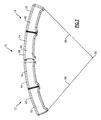
- FIG. 1 illustrates a side view of a suture tensioning device
- FIG. 2 illustrates an exploded view of a first handle and a second handle of the suture tensioning device
- FIG. 3 illustrates a side view of the second handle of the suture tensioning device
- FIG. 4 illustrates a cross-sectional side view of the second handle of the suture tensioning device
- FIG. 5 illustrates a cleat and a groove of the second handle of the suture tensioning device
- FIG. 6 illustrates a first example of tensioning a suture with the suture tensioning device
- FIG. 7 illustrates a second example of tensioning a suture with the suture tensioning device.
- FIG. 1 illustrates a suture tensioning device 10 employed to tension two sutures tails 94 or sutures 98 (shown in FIGS. 6 and 7 , respectively) during a surgical procedure.
- the suture tensioning device 10 includes a first handle 12 and a second handle 14 that can be connected together or used individually by disconnecting the first handle 12 and the second handle 14 .
- the first handle 12 and the second handle 14 of the suture tensioning device 10 are made of plastic.
- Each of the first handle 12 and the second handle 14 have a slightly arcuate shape, and the suture tensioning device 10 has an arcuate shape when the first handle 12 and the second handle 14 are attached together.
- the first handle 12 includes a first portion 16 and a second portion 18 .
- the first portion 16 and the second portion 18 each includes a bore (the first portion 16 includes a bore 20 as shown in FIG. 2 ) that align to receive an alignment feature 22 that aligns the first portion 16 and the second portion 18 relative to each other.
- the alignment feature 22 is a pin.
- the first portion 16 includes a bore 24 that extends through a length L 1 of the first portion 16
- the second portion 18 includes a bore (not shown) and that extends partially through a length L 2 of the second portion 18 and aligns with the bore 24 of the first portion 16 .
- a fastener 26 is received in the aligned bores 24 to secure the first portion 16 and the second portion 18 together.
- the fastener 26 is a threaded fastener 28 .
- the first portion 16 includes an outer side surface 30 and an opposing inner side surface 32 .
- the bore 24 extends between the side surfaces 30 and 32 .
- the second portion 18 includes an inner side surface 34 and an outer side surface 36 .
- the bore (not shown) of the second portion 18 extends from the inner side surface 34 of the second portion 18 and partially through the length L 2 of the second portion 18 .
- the fastener 26 is inserted into the bore 24 from the outer side surface 30 of the first portion 16 and then enters into the bore (not shown) of the second portion 18 .
- a portion of the inner side surface 32 of the first portion 16 contacts a portion of the inner side surface 34 of the second portion 18 .
- the outer side surface 36 of the second portion 18 includes a locking projection 38 .
- Each of the first portion 16 and the second portion 18 of the first handle 12 includes an upper curved surface 40 and a lower curved surface 42 .
- a groove 44 is located on the outer side surfaces 30 and 36 and the upper curved surface 40 .
- the second handle 14 includes a first portion 46 and a second portion 48 .
- the first portion 46 and the second portion 48 each include a bore ( FIG. 2 shows the bore 50 of the first portion 46 ) that align to receive an alignment feature 52 that aligns the first portion 46 and the second portion 48 relative to each other.
- the alignment feature 52 is a pin.
- the first portion 46 includes a bore 54 that extends through a length L 3 of the first portion 46
- the second portion 48 includes a bore 55 that extends partially through a length L 4 of the second portion 48 .
- a fastener 56 is received in the aligned bores 54 and 55 to secure the first portion 46 and the second portion 48 together.
- the fastener 56 is a threaded fastener 58 .
- the first portion 46 includes an outer side surface 60 and an opposing inner side surface 62 , and the bore 54 extends between the side surfaces 60 and 62 .
- the second portion 48 includes an inner side surface 64 and an outer side surface 66 , and the bore 55 extends from the inner side surface 64 of the second portion 48 .
- the fastener 56 is inserted into the bore 54 from the outer side surface 60 of the first portion 46 . When attached, a portion of the inner side surface 62 of the first portion 46 contacts a portion of the inner side surface 64 of the second portion 48 .
- Each of the first portion 46 and the second portion 48 of the first handle 12 also includes an upper curved surface 70 and a lower curved surface 72 .
- a groove 74 is located on the outer side surfaces 60 and 66 and the upper curved surface 70 .
- the outer side surface 66 of the second portion 48 includes a recess 68 .
- the locking projection 38 of the first handle 12 is received in the recess 68 of the second handle 14 to remotely attach the first handle 12 to the second handle 14 and define the suture tensioning device 10 .
- a bore 76 extends from the outer side surface 66 of the second handle 14 and partially through the length L 4 of the second portion 48 .
- a plunger 78 received in the bore 76 is resiliently biased outwardly to provide tactile feedback when the locking projection 38 of the first handle 12 is received in the recess 68 of the second handle 14 , allowing the handles 12 and 14 to be easily connected and detached from each other.
- FIGS. 3 and 4 illustrate the second handle 14 of the suture tensioning device 10
- the first handle 12 includes similar features and structures, except the first handle 12 does not include the recess 68 , the bore 76 and the plunger 78 , and the first handle 12 does include the locking projection 38 .
- Each of the inner side surfaces 32 and 34 of the first handle 12 and the inner side surfaces 62 and 64 of the second handle 14 include a flattened surface 80 , an upper beveled surface 82 and a lower beveled surface 84 .
- the flattened surfaces 80 of the first handle 12 contact when the first portion 16 and the second portion 18 of the first handle 12 are secured together with the fastener 26
- the flattened surfaces 80 of the second handle 14 contact when the first portion 46 and the second portion 48 of the second handle 14 are secured together with the fastener 56 . This allows the first handle 12 and the second handle 14 to be used individually and separately.
- FIG. 4 when the first portion 46 and the second portion 48 of the second handle 14 are attached, a cleat 86 is defined between each of the upper beveled surfaces 82 and also between each of the lower beveled surfaces 84 .
- FIG. 5 illustrates an area A of FIG. 4 showing the cleat 86 of the second handle 14 .
- a cleat (not shown) is defined between each of the upper beveled surfaces 82 and also between each of the lower beveled surfaces 84 .
- Another upper beveled surface 88 is located outwardly of each of the upper beveled surfaces 82
- another lower beveled surface 90 is located outwardly of each of the lower beveled surfaces 84 .
- the suture tensioning device 10 is employed to tension two suture tails 94 that are connected at a common area 96 during a surgical procedure.
- the suture tensioning device 10 can be Tightrope®, a registered trademark of Arthrex, Inc. of Naples, Fla.
- one suture tail 94 is wedged in the cleat 86 of each of the handles 12 and 14 of the suture tensioning device 10 , securing the suture tails 94 to the suture tensioning device 10 during a surgical procedure.
- This allows the suture tensioning device 10 to firmly, securely, and atraumatically secure the suture tails 94 in a quick and simple manner, allowing a surgeon or other medical professional to tension the suture tails 94 as needed during a surgical procedure.
- the cleat 86 both retains the suture tails 94 and guides the suture tails 94 between the two handles 12 and 14 .
- the handles 12 and 14 can be connected as shown in FIG. 6 , or the handles 12 and 14 can be separated such that one handle 12 and 14 is held in each hand.
- each of the suture tails 94 are received in one of the grooves 92 , and the suture tails 94 are wrapped around the handles 12 and 14 .
- the handles 12 and 14 can be connected as shown in FIG. 6 , or the handles 12 and 14 can be separated such that one handle 12 and 14 is held in each hand.
- a single suture 98 is received in the grooves 44 and 74 (the suture 98 is partially shown in dotted lines in FIG. 7 when received in the grooves 44 and 74 ) located on the outer side surfaces 30 and 60 , respectively, and the upper curved surfaces 40 and 70 , respectively, of the first handle 12 and the second handle 14 , respectively, of the suture tensioning device 10 . Portions of the single suture 98 also meet in the common area 96 .
- the handles 12 and 14 can be connected as shown in FIG. 7 , or separated such that one handle 12 and 14 is held in each hand.
- Minimal suture wraps are needed to secure the suture tails 94 or the suture 98 to the suture tensioning device 10 , simplifying use.
- a suture tail 94 or a suture 98 has been illustrated and described, wire, tape, or any time of material that needs to be tensioned during a surgical procedure can be employed.
Landscapes
- Health & Medical Sciences (AREA)
- Life Sciences & Earth Sciences (AREA)
- Surgery (AREA)
- Heart & Thoracic Surgery (AREA)
- Engineering & Computer Science (AREA)
- Biomedical Technology (AREA)
- Nuclear Medicine, Radiotherapy & Molecular Imaging (AREA)
- Medical Informatics (AREA)
- Molecular Biology (AREA)
- Animal Behavior & Ethology (AREA)
- General Health & Medical Sciences (AREA)
- Public Health (AREA)
- Veterinary Medicine (AREA)
- Surgical Instruments (AREA)
Priority Applications (3)
| Application Number | Priority Date | Filing Date | Title |
|---|---|---|---|
| US14/091,400 US9913640B2 (en) | 2013-03-13 | 2013-11-27 | Suture tensioning device |
| DE112014001329.3T DE112014001329T5 (de) | 2013-03-13 | 2014-03-06 | Fadenspannvorrichtung |
| PCT/US2014/021045 WO2014164178A2 (fr) | 2013-03-13 | 2014-03-06 | Dispositif de mise sous tension de suture |
Applications Claiming Priority (2)
| Application Number | Priority Date | Filing Date | Title |
|---|---|---|---|
| US201361778717P | 2013-03-13 | 2013-03-13 | |
| US14/091,400 US9913640B2 (en) | 2013-03-13 | 2013-11-27 | Suture tensioning device |
Publications (2)
| Publication Number | Publication Date |
|---|---|
| US20140276990A1 US20140276990A1 (en) | 2014-09-18 |
| US9913640B2 true US9913640B2 (en) | 2018-03-13 |
Family
ID=51531035
Family Applications (1)
| Application Number | Title | Priority Date | Filing Date |
|---|---|---|---|
| US14/091,400 Active 2036-06-22 US9913640B2 (en) | 2013-03-13 | 2013-11-27 | Suture tensioning device |
Country Status (3)
| Country | Link |
|---|---|
| US (1) | US9913640B2 (fr) |
| DE (1) | DE112014001329T5 (fr) |
| WO (1) | WO2014164178A2 (fr) |
Cited By (14)
| Publication number | Priority date | Publication date | Assignee | Title |
|---|---|---|---|---|
| US10045788B2 (en) | 2006-12-11 | 2018-08-14 | Arthrosurface Incorporated | Retrograde resection apparatus and method |
| US10076343B2 (en) | 2002-12-03 | 2018-09-18 | Arthrosurface Incorporated | System for articular surface replacement |
| US10307172B2 (en) | 2012-07-03 | 2019-06-04 | Arthrosurface Incorporated | System and method for joint resurfacing and repair |
| US10478200B2 (en) | 2009-04-17 | 2019-11-19 | Arthrosurface Incorporated | Glenoid resurfacing system and method |
| US10575957B2 (en) | 2014-03-07 | 2020-03-03 | Arthrosurface Incoporated | Anchor for an implant assembly |
| US10624749B2 (en) | 2003-02-24 | 2020-04-21 | Arthrosurface Incorporated | Trochlear resurfacing system and method |
| US10624752B2 (en) | 2006-07-17 | 2020-04-21 | Arthrosurface Incorporated | Tibial resurfacing system and method |
| US10624748B2 (en) | 2014-03-07 | 2020-04-21 | Arthrosurface Incorporated | System and method for repairing articular surfaces |
| US10695096B2 (en) | 2013-04-16 | 2020-06-30 | Arthrosurface Incorporated | Suture system and method |
| US10945743B2 (en) | 2009-04-17 | 2021-03-16 | Arthrosurface Incorporated | Glenoid repair system and methods of use thereof |
| US11160663B2 (en) | 2017-08-04 | 2021-11-02 | Arthrosurface Incorporated | Multicomponent articular surface implant |
| US11478358B2 (en) | 2019-03-12 | 2022-10-25 | Arthrosurface Incorporated | Humeral and glenoid articular surface implant systems and methods |
| US11607319B2 (en) | 2014-03-07 | 2023-03-21 | Arthrosurface Incorporated | System and method for repairing articular surfaces |
| US11712276B2 (en) | 2011-12-22 | 2023-08-01 | Arthrosurface Incorporated | System and method for bone fixation |
Families Citing this family (9)
| Publication number | Priority date | Publication date | Assignee | Title |
|---|---|---|---|---|
| US6610067B2 (en) | 2000-05-01 | 2003-08-26 | Arthrosurface, Incorporated | System and method for joint resurface repair |
| EP2314257B9 (fr) | 2000-05-01 | 2013-02-27 | ArthroSurface, Inc. | Système de réparation de rectification de joint |
| AU2006203909A1 (en) | 2003-11-20 | 2006-07-13 | Arthrosurface, Inc. | System and method for retrograde procedure |
| US7828853B2 (en) | 2004-11-22 | 2010-11-09 | Arthrosurface, Inc. | Articular surface implant and delivery system |
| WO2009111481A1 (fr) | 2008-03-03 | 2009-09-11 | Arthrosurface Incorporated | Système de resurfaçage d'os et procédé |
| US9283076B2 (en) | 2009-04-17 | 2016-03-15 | Arthrosurface Incorporated | Glenoid resurfacing system and method |
| US9066716B2 (en) | 2011-03-30 | 2015-06-30 | Arthrosurface Incorporated | Suture coil and suture sheath for tissue repair |
| US12521227B2 (en) | 2019-06-18 | 2026-01-13 | Smith & Nephew, Inc. | Methods and devices for tissue graft fixation |
| WO2022232126A1 (fr) * | 2021-04-26 | 2022-11-03 | Smith & Nephew, Inc. | Dispositifs et procédés de réparation d'articulation |
Citations (10)
| Publication number | Priority date | Publication date | Assignee | Title |
|---|---|---|---|---|
| US4823794A (en) | 1982-07-12 | 1989-04-25 | Pierce William S | Surgical pledget |
| WO1995032669A1 (fr) | 1994-06-01 | 1995-12-07 | Perclose, Inc. | Procedes et appareils servant a faire avancer des noeuds chirurgicaux |
| US20040102809A1 (en) * | 2002-11-26 | 2004-05-27 | Anderson Steven C. | Multi-element biased suture clip |
| US20050131430A1 (en) | 2003-12-12 | 2005-06-16 | Arvik Enterprises, Llc | Suturing device |
| US20070021781A1 (en) | 2005-07-22 | 2007-01-25 | Jervis James E | Wedge Operated Retainer Device And Methods |
| US20080275477A1 (en) | 2007-05-02 | 2008-11-06 | Arthrex, Inc. | Suture tensioning device |
| US20090248028A1 (en) * | 2008-03-26 | 2009-10-01 | Anthony Alexander | Systems and Methods of Anchoring Surgical Wires, Catheters, and other Medical Objects |
| US20100001038A1 (en) | 2008-07-02 | 2010-01-07 | Shalom Levin | Pivoting tacker |
| US20100305571A1 (en) | 2009-06-02 | 2010-12-02 | Kinamed, Inc. | Surgical cable tensioning system |
| US8123806B1 (en) | 2008-05-09 | 2012-02-28 | Cayenne Medical, Inc | Method of tensioning a tissue graft having suture bundles using a cleated bar |
-
2013
- 2013-11-27 US US14/091,400 patent/US9913640B2/en active Active
-
2014
- 2014-03-06 DE DE112014001329.3T patent/DE112014001329T5/de not_active Withdrawn
- 2014-03-06 WO PCT/US2014/021045 patent/WO2014164178A2/fr not_active Ceased
Patent Citations (10)
| Publication number | Priority date | Publication date | Assignee | Title |
|---|---|---|---|---|
| US4823794A (en) | 1982-07-12 | 1989-04-25 | Pierce William S | Surgical pledget |
| WO1995032669A1 (fr) | 1994-06-01 | 1995-12-07 | Perclose, Inc. | Procedes et appareils servant a faire avancer des noeuds chirurgicaux |
| US20040102809A1 (en) * | 2002-11-26 | 2004-05-27 | Anderson Steven C. | Multi-element biased suture clip |
| US20050131430A1 (en) | 2003-12-12 | 2005-06-16 | Arvik Enterprises, Llc | Suturing device |
| US20070021781A1 (en) | 2005-07-22 | 2007-01-25 | Jervis James E | Wedge Operated Retainer Device And Methods |
| US20080275477A1 (en) | 2007-05-02 | 2008-11-06 | Arthrex, Inc. | Suture tensioning device |
| US20090248028A1 (en) * | 2008-03-26 | 2009-10-01 | Anthony Alexander | Systems and Methods of Anchoring Surgical Wires, Catheters, and other Medical Objects |
| US8123806B1 (en) | 2008-05-09 | 2012-02-28 | Cayenne Medical, Inc | Method of tensioning a tissue graft having suture bundles using a cleated bar |
| US20100001038A1 (en) | 2008-07-02 | 2010-01-07 | Shalom Levin | Pivoting tacker |
| US20100305571A1 (en) | 2009-06-02 | 2010-12-02 | Kinamed, Inc. | Surgical cable tensioning system |
Non-Patent Citations (3)
| Title |
|---|
| International Preliminary Report on Patentability for International Application No. PCT/US2014/021045 dated Sep. 24, 2015. |
| International Search Report & Written Opinion for International Application No. PCT/US2014/021045 dated Oct. 23, 2014. |
| Invitation to Pay Additional Fees and, Where Applicable, Protest Fee for International Application No. PCT/US2014/021045 dated May 25, 2014. |
Cited By (23)
| Publication number | Priority date | Publication date | Assignee | Title |
|---|---|---|---|---|
| US10076343B2 (en) | 2002-12-03 | 2018-09-18 | Arthrosurface Incorporated | System for articular surface replacement |
| US11337819B2 (en) | 2003-02-24 | 2022-05-24 | Arthrosurface Incorporated | Trochlear resurfacing system and method |
| US10624749B2 (en) | 2003-02-24 | 2020-04-21 | Arthrosurface Incorporated | Trochlear resurfacing system and method |
| US10624752B2 (en) | 2006-07-17 | 2020-04-21 | Arthrosurface Incorporated | Tibial resurfacing system and method |
| US11471289B2 (en) | 2006-07-17 | 2022-10-18 | Arthrosurface Incorporated | Tibial resurfacing system and method |
| US10959740B2 (en) | 2006-12-11 | 2021-03-30 | Arthrosurface Incorporated | Retrograde resection apparatus and method |
| US10045788B2 (en) | 2006-12-11 | 2018-08-14 | Arthrosurface Incorporated | Retrograde resection apparatus and method |
| US11478259B2 (en) | 2009-04-17 | 2022-10-25 | Arthrosurface, Incorporated | Glenoid resurfacing system and method |
| US10478200B2 (en) | 2009-04-17 | 2019-11-19 | Arthrosurface Incorporated | Glenoid resurfacing system and method |
| US10945743B2 (en) | 2009-04-17 | 2021-03-16 | Arthrosurface Incorporated | Glenoid repair system and methods of use thereof |
| US11712276B2 (en) | 2011-12-22 | 2023-08-01 | Arthrosurface Incorporated | System and method for bone fixation |
| US10307172B2 (en) | 2012-07-03 | 2019-06-04 | Arthrosurface Incorporated | System and method for joint resurfacing and repair |
| US11191552B2 (en) | 2012-07-03 | 2021-12-07 | Arthrosurface, Incorporated | System and method for joint resurfacing and repair |
| US11648036B2 (en) | 2013-04-16 | 2023-05-16 | Arthrosurface Incorporated | Suture system and method |
| US10695096B2 (en) | 2013-04-16 | 2020-06-30 | Arthrosurface Incorporated | Suture system and method |
| US11083587B2 (en) | 2014-03-07 | 2021-08-10 | Arthrosurface Incorporated | Implant and anchor assembly |
| US10624748B2 (en) | 2014-03-07 | 2020-04-21 | Arthrosurface Incorporated | System and method for repairing articular surfaces |
| US11607319B2 (en) | 2014-03-07 | 2023-03-21 | Arthrosurface Incorporated | System and method for repairing articular surfaces |
| US10624754B2 (en) | 2014-03-07 | 2020-04-21 | Arthrosurface Incorporated | System and method for repairing articular surfaces |
| US10575957B2 (en) | 2014-03-07 | 2020-03-03 | Arthrosurface Incoporated | Anchor for an implant assembly |
| US11766334B2 (en) | 2014-03-07 | 2023-09-26 | Arthrosurface Incorporated | System and method for repairing articular surfaces |
| US11160663B2 (en) | 2017-08-04 | 2021-11-02 | Arthrosurface Incorporated | Multicomponent articular surface implant |
| US11478358B2 (en) | 2019-03-12 | 2022-10-25 | Arthrosurface Incorporated | Humeral and glenoid articular surface implant systems and methods |
Also Published As
| Publication number | Publication date |
|---|---|
| DE112014001329T5 (de) | 2016-02-18 |
| WO2014164178A2 (fr) | 2014-10-09 |
| WO2014164178A3 (fr) | 2014-12-11 |
| US20140276990A1 (en) | 2014-09-18 |
Similar Documents
| Publication | Publication Date | Title |
|---|---|---|
| US9913640B2 (en) | Suture tensioning device | |
| US8936628B2 (en) | Suture-retaining sternal clamp assembly | |
| US8202297B2 (en) | Technique for tissue fixation by reeling in and anchoring suture attached to tissue | |
| AU2007202269B2 (en) | Swivel anchor and method for knotless fixation of tissue | |
| US10743856B2 (en) | Non-sliding soft anchor | |
| US20120290017A1 (en) | Bone fracture fixation clamp | |
| US10052091B2 (en) | Knotless suture or tissue fixation using an implant having a pointed tip | |
| US20220142689A1 (en) | Implant for Bone Fixation | |
| US10349996B2 (en) | Apparatus, system, and method for securing a tensioned cable through or around bone | |
| ATE492218T1 (de) | Hochfeste kettenartige naht mit schlaufen zur knotenlosen befestigung | |
| WO2005086651A3 (fr) | Ensemble de vis pediculaire polyaxiale | |
| WO2004016181A3 (fr) | Agrafe pour suture du sternum | |
| DE602004019633D1 (de) | Knotenloser Nahtmaterialanker mit Nahtmaterial | |
| ATE447374T1 (de) | Polyaxiale stielschraubenanordnung mit vorspannwinkel | |
| WO2002047564A3 (fr) | Pince a broches multiples et attache de tige | |
| EP3750497A3 (fr) | Dispositif de sangle de fermeture sternale | |
| KR101670777B1 (ko) | 대퇴골 고정 시스템 | |
| US9782161B1 (en) | Suture locking loops and method of use | |
| CN215994214U (zh) | 带倒刺钛缆防滑内固定系统 | |
| US11109954B2 (en) | Anchor for medical use, to be inserted into a bony wall | |
| US20060058814A1 (en) | Circumcision clamp | |
| CN201759657U (zh) | 张力带固定装置 | |
| US20200268426A1 (en) | Medical fixation device for polymer cables | |
| KR20200090542A (ko) | 골절 수술용 긴장대 골압박 고정장치 | |
| US20180360511A1 (en) | Human bone treatment unit |
Legal Events
| Date | Code | Title | Description |
|---|---|---|---|
| AS | Assignment |
Owner name: ARTHREX, INC., FLORIDA Free format text: ASSIGNMENT OF ASSIGNORS INTEREST;ASSIGNOR:PEREZ, ARLEY, III;REEL/FRAME:031683/0511 Effective date: 20131126 |
|
| STCF | Information on status: patent grant |
Free format text: PATENTED CASE |
|
| MAFP | Maintenance fee payment |
Free format text: PAYMENT OF MAINTENANCE FEE, 4TH YEAR, LARGE ENTITY (ORIGINAL EVENT CODE: M1551); ENTITY STATUS OF PATENT OWNER: LARGE ENTITY Year of fee payment: 4 |
|
| MAFP | Maintenance fee payment |
Free format text: PAYMENT OF MAINTENANCE FEE, 8TH YEAR, LARGE ENTITY (ORIGINAL EVENT CODE: M1552); ENTITY STATUS OF PATENT OWNER: LARGE ENTITY Year of fee payment: 8 |