US9920569B2 - Closure member and the method of making the same - Google Patents
Closure member and the method of making the same Download PDFInfo
- Publication number
- US9920569B2 US9920569B2 US15/186,007 US201615186007A US9920569B2 US 9920569 B2 US9920569 B2 US 9920569B2 US 201615186007 A US201615186007 A US 201615186007A US 9920569 B2 US9920569 B2 US 9920569B2
- Authority
- US
- United States
- Prior art keywords
- closure member
- panels
- hollow interior
- ribs
- board
- Prior art date
- Legal status (The legal status is an assumption and is not a legal conclusion. Google has not performed a legal analysis and makes no representation as to the accuracy of the status listed.)
- Active
Links
Images




Classifications
-
- E—FIXED CONSTRUCTIONS
- E06—DOORS, WINDOWS, SHUTTERS, OR ROLLER BLINDS IN GENERAL; LADDERS
- E06B—FIXED OR MOVABLE CLOSURES FOR OPENINGS IN BUILDINGS, VEHICLES, FENCES OR LIKE ENCLOSURES IN GENERAL, e.g. DOORS, WINDOWS, BLINDS, GATES
- E06B3/00—Window sashes, door leaves, or like elements for closing wall or like openings; Layout of fixed or moving closures, e.g. windows in wall or like openings; Features of rigidly-mounted outer frames relating to the mounting of wing frames
- E06B3/70—Door leaves
- E06B3/7015—Door leaves characterised by the filling between two external panels
-
- B29C47/0028—
-
- B—PERFORMING OPERATIONS; TRANSPORTING
- B29—WORKING OF PLASTICS; WORKING OF SUBSTANCES IN A PLASTIC STATE IN GENERAL
- B29C—SHAPING OR JOINING OF PLASTICS; SHAPING OF MATERIAL IN A PLASTIC STATE, NOT OTHERWISE PROVIDED FOR; AFTER-TREATMENT OF THE SHAPED PRODUCTS, e.g. REPAIRING
- B29C48/00—Extrusion moulding, i.e. expressing the moulding material through a die or nozzle which imparts the desired form; Apparatus therefor
- B29C48/03—Extrusion moulding, i.e. expressing the moulding material through a die or nozzle which imparts the desired form; Apparatus therefor characterised by the shape of the extruded material at extrusion
- B29C48/09—Articles with cross-sections having partially or fully enclosed cavities, e.g. pipes or channels
- B29C48/11—Articles with cross-sections having partially or fully enclosed cavities, e.g. pipes or channels comprising two or more partially or fully enclosed cavities, e.g. honeycomb-shaped
-
- E—FIXED CONSTRUCTIONS
- E06—DOORS, WINDOWS, SHUTTERS, OR ROLLER BLINDS IN GENERAL; LADDERS
- E06B—FIXED OR MOVABLE CLOSURES FOR OPENINGS IN BUILDINGS, VEHICLES, FENCES OR LIKE ENCLOSURES IN GENERAL, e.g. DOORS, WINDOWS, BLINDS, GATES
- E06B3/00—Window sashes, door leaves, or like elements for closing wall or like openings; Layout of fixed or moving closures, e.g. windows in wall or like openings; Features of rigidly-mounted outer frames relating to the mounting of wing frames
- E06B3/54—Fixing of glass panes or like plates
- E06B3/58—Fixing of glass panes or like plates by means of borders, cleats, or the like
- E06B3/5892—Fixing of window panes in openings in door leaves
-
- E—FIXED CONSTRUCTIONS
- E06—DOORS, WINDOWS, SHUTTERS, OR ROLLER BLINDS IN GENERAL; LADDERS
- E06B—FIXED OR MOVABLE CLOSURES FOR OPENINGS IN BUILDINGS, VEHICLES, FENCES OR LIKE ENCLOSURES IN GENERAL, e.g. DOORS, WINDOWS, BLINDS, GATES
- E06B3/00—Window sashes, door leaves, or like elements for closing wall or like openings; Layout of fixed or moving closures, e.g. windows in wall or like openings; Features of rigidly-mounted outer frames relating to the mounting of wing frames
- E06B3/70—Door leaves
- E06B3/7015—Door leaves characterised by the filling between two external panels
- E06B3/7017—Door leaves characterised by the filling between two external panels of grating type
-
- B29C47/0061—
-
- B—PERFORMING OPERATIONS; TRANSPORTING
- B29—WORKING OF PLASTICS; WORKING OF SUBSTANCES IN A PLASTIC STATE IN GENERAL
- B29C—SHAPING OR JOINING OF PLASTICS; SHAPING OF MATERIAL IN A PLASTIC STATE, NOT OTHERWISE PROVIDED FOR; AFTER-TREATMENT OF THE SHAPED PRODUCTS, e.g. REPAIRING
- B29C48/00—Extrusion moulding, i.e. expressing the moulding material through a die or nozzle which imparts the desired form; Apparatus therefor
- B29C48/001—Combinations of extrusion moulding with other shaping operations
- B29C48/002—Combinations of extrusion moulding with other shaping operations combined with surface shaping
-
- B—PERFORMING OPERATIONS; TRANSPORTING
- B29—WORKING OF PLASTICS; WORKING OF SUBSTANCES IN A PLASTIC STATE IN GENERAL
- B29K—INDEXING SCHEME ASSOCIATED WITH SUBCLASSES B29B, B29C OR B29D, RELATING TO MOULDING MATERIALS OR TO MATERIALS FOR MOULDS, REINFORCEMENTS, FILLERS OR PREFORMED PARTS, e.g. INSERTS
- B29K2027/00—Use of polyvinylhalogenides or derivatives thereof as moulding material
- B29K2027/06—PVC, i.e. polyvinylchloride
-
- B—PERFORMING OPERATIONS; TRANSPORTING
- B29—WORKING OF PLASTICS; WORKING OF SUBSTANCES IN A PLASTIC STATE IN GENERAL
- B29L—INDEXING SCHEME ASSOCIATED WITH SUBCLASS B29C, RELATING TO PARTICULAR ARTICLES
- B29L2031/00—Other particular articles
- B29L2031/724—Doors
-
- E—FIXED CONSTRUCTIONS
- E06—DOORS, WINDOWS, SHUTTERS, OR ROLLER BLINDS IN GENERAL; LADDERS
- E06B—FIXED OR MOVABLE CLOSURES FOR OPENINGS IN BUILDINGS, VEHICLES, FENCES OR LIKE ENCLOSURES IN GENERAL, e.g. DOORS, WINDOWS, BLINDS, GATES
- E06B3/00—Window sashes, door leaves, or like elements for closing wall or like openings; Layout of fixed or moving closures, e.g. windows in wall or like openings; Features of rigidly-mounted outer frames relating to the mounting of wing frames
- E06B3/70—Door leaves
- E06B2003/7049—Specific panel characteristics
-
- E—FIXED CONSTRUCTIONS
- E06—DOORS, WINDOWS, SHUTTERS, OR ROLLER BLINDS IN GENERAL; LADDERS
- E06B—FIXED OR MOVABLE CLOSURES FOR OPENINGS IN BUILDINGS, VEHICLES, FENCES OR LIKE ENCLOSURES IN GENERAL, e.g. DOORS, WINDOWS, BLINDS, GATES
- E06B3/00—Window sashes, door leaves, or like elements for closing wall or like openings; Layout of fixed or moving closures, e.g. windows in wall or like openings; Features of rigidly-mounted outer frames relating to the mounting of wing frames
- E06B3/70—Door leaves
- E06B3/82—Flush doors, i.e. with completely flat surface
Definitions
- the present invention relates to a closure member and the method of making the same, for example particularly, but not exclusively, a door formed by extrusion.
- a closure member includes a door which is a movable structure used to close off an entrance, typically consisting of a panel that swings on hinges or that slides or rotate.
- Conventional doors with relatively high mechanical or structural strength are usually heavy and expensive to produce. The production of such a door involves numerous steps including trimming, edge beveling, sanding etc. Decorating or modifying such a door with desirable shape and patterns would involve time-consuming shaping method with considerable wastage.
- the invention seeks to eliminate or at least to mitigate such shortcomings by providing a new or otherwise improved closure member and a method of making the same.
- the door is flexible and adaptable to versatile applications.
- a closure member of a preferred configuration comprising a board having a major axis and two panels sandwiching a hollow interior that is partitioned by a plurality of ribs positioned at intervals therein, the hollow interior is delimited in a first direction by a pair of opposite end walls, wherein the hollow interior is accessible in a second direction which is substantially traverse to the first direction, and at least one of the two panels is textured during the formation of the board to form a textured outer surface of the closure member.
- the pair of opposite end walls forms the left and right side walls of the closure member.
- the hollow interior is closed off in the second direction by a cover.
- the cover includes an insertion insertable into the hollow interior of the board.
- the panels, the ribs and the opposite end walls are formed by extrusion.
- the panels, the ribs and the opposite end walls are integrally formed as one piece.
- the hollow interior is filled with a preferred reinforcement means.
- a closure member of a preferred configuration comprising a board having a major axis and two panels sandwiching a hollow interior that is partitioned by a plurality of ribs positioned at intervals, the hollow interior is delimited in a first direction by a pair of opposite end walls, wherein the hollow interior is occupied by reinforcement means.
- the hollow interior is partitioned at intervals to form discrete elongate spaces that extends along the major axis.
- discrete elongate space is filled with the reinforcement means which is preformed into an elongate piece and dimensioned to be fitted into the discrete elongate space for enhancing the tensile strength of the board.
- the elongate piece is made of a material selected from a group consisting of wood, plastic and metal.
- the insertion is insertable into an end portion of the discrete elongate space to prevent access to the hollow interior.
- the ribs extend parallel to the major axis in the hollow interior, and are closer apart in a region adjacent at least one of the end walls of the board than those in a region at or adjacent the centre of the board.
- At least one of the panels is textured by way of having one or more grooves thereon.
- At least one of the panels is decorated with a decoration fixed to thereto.
- the decoration is press fit into the groove.
- At least one of the panels is textured by way of having one or more shaped grooves thereon which are formed together with the rest of the overall closure member by way of extrusion, and the decoration includes a base having a shape corresponding to that of the groove and is attached to the groove.
- the panel includes an aperture for accommodating a part of the decoration
- the decoration includes a deformable anchor for insertion into the aperture when compressed and thereafter for abutting an underside of the panel when expanded.
- both of the panels have apertures formed at corresponding position for accommodating respective decoration which are provided with a coupler for inter-engagement between the panels.
- the decoration is fixed to the panel by a two part coupler, with one part being provided on an inner side of the panel coupling with another part being provided on an outside of the panel.
- the board includes an aperture which extend across the hollow interior and beyond the panels to form a through hole for accommodating a window with frame therein.
- a method of forming a closure member as discussed above comprising the step of forming a board by way of extrusion, the board has a major axis and two panels sandwiching a hollow interior that is partitioned by a plurality of ribs positioned at intervals, the hollow interior is delimited in a first direction by a pair of opposite end walls, texturing at least one of said panels during the formation of the board by way of rolling a textured roller 200 thereon.
- the ribs and the pair of opposite end walls are integrally formed by way of extrusion.
- the hollow interior is partitioned at intervals to form discrete elongate spaces extending along the major axis.
- a method of forming a closure member comprising the step of forming a board by way of extrusion, the board has a major axis and two panels sandwiching a hollow interior that is partitioned by a plurality of ribs positioned at intervals to form discrete elongate spaces, the hollow interior is delimited in a first direction by a pair of opposite end walls, filling at least one of the discrete elongate spaces with reinforcement means.
- the step of texturing at least one of said panels during the formation of the board by way of rolling a textured roller 200 thereon.
- the discrete elongate space is filled with the reinforcement means which is preformed into an elongate piece and dimensioned to be fitted into the discrete elongate space, the reinforcement means enhances the tensile strength of the board.
- the method further including the step of closing off the hollow interior by a cover.
- the cover includes an insertion insertable into the hollow interior of the board.
- the insertion is insertable into an end portion of the discrete elongate space to prevent access to the hollow interior
- the method further comprising the step of decorating the panel by a decoration.
- the step of decorating the panel by a decoration involve fixing the decoration to the panel by a two part coupler, with one part being provided on an inner side of the panel coupling with another part being provided on an outside of the panel.
- the method further comprising the step of providing an aperture on the board, wherein the aperture extends across the hollow interior and beyond the panels to form a through hole for accommodating a window and frame therewith.
- the panel has at least one groove formed with the rest of the board by way of extrusion.
- the panel has at least one depression formed by rolling over the panel a textured roller 200 with at least one protrusion.
- the step of decorating the panel by a decoration involve providing a shaped groove to the panel during extrusion, and attaching a decoration with a shape corresponding to shape of the groove.
- the step of decorating the panel by a decoration involves drilling an aperture on the panel, providing a decoration with a deformable anchor, compressing the anchor for insertion into the aperture and expanding the anchor for abutment with an underside of the panel.
- the step of decorating the panel by a decoration involves drilling corresponding apertures on each panel, providing a decoration, which has two parts couplable by way of a coupler, fixing the parts of the decoration to respective aperture on respective panel, and inter-engaging the coupler between the panels.
- a closure member of a preferred configuration comprising a board having a major axis and two panels sandwiching a hollow interior that is partitioned by a plurality of ribs positioned at intervals, the hollow interior is delimited in a first direction by a pair of opposite end walls, wherein the plurality of ribs includes first rib that extend parallel to the major axis in the hollow interior and at least one second rib that extends traverse to the major axis in the hollow interior.
- the hollow interior is occupied by reinforcement means.
- the second rib contributes to an overall thermal transmission (U value) of the closure member by increasing a thermal resistance (R value).
- the thermal resistance is a sum of thermal resistance in each layer of material in the closure member.
- FIG. 1 is a perspective view of a first embodiment of a door according to the invention
- FIG. 2 is an enlarged cross sectional view taken along width of the door in FIG. 1 ;
- FIG. 3A is a perspective view of a second embodiment of a door according to the invention.
- FIG. 3B is an enlarged cross sectional view taken across length of the door in FIG. 3A showing part of that door;
- FIGS. 4A and 4B are perspective view of a third embodiment of a door according to the invention.
- FIG. 4C is an enlarged cross-sectional view of a part of the door in FIG. 4A taken along line A-A′;
- FIG. 5A is a perspective view of a further embodiment of a door according to the invention.
- FIG. 5B is a cross-sectional view of a part of the door in FIG. 5A ;
- FIG. 6 is an enlarged perspective cross sectional view of the door in FIG. 1 with reinforcement means
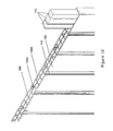
- FIG. 7 is a perspective view of an extrusion process for production of the door in FIG. 1 ;
- FIG. 8 is a cross-sectional view of a part of the door in FIG. 1 with decorations press fit into a groove formed by way of extrusion with the rest of the door.
- FIG. 9A is a perspective exploded view of a further embodiment of a door according to the invention.
- FIG. 9B is a cross sectional view taken along length of the door in FIG. 9A ;
- FIG. 10 is an enlarged view of a part of the cross sectional view in FIG. 9B ;
- FIG. 11A is a perspective exploded view of another embodiment of a door according to the invention.
- FIG. 11B is an enlarged cross-sectional view taken along length of the door in FIG. 11A showing part of the door;
- FIG. 12A is a front view of the door in FIGS. 9A and 9B with decorative accessories;
- FIG. 12B is a perspective view of the door in FIG. 12A ;
- FIG. 12C is an enlarged cross-sectional view of the door in FIGS. 12A and 12B showing first and second arrangements of the decorative accessories on the door;
- FIG. 12D is an enlarged cross-sectional view of a part of the door in FIGS. 12A and 12B showing a third arrangement of the decorative accessory on the door;
- FIG. 13A is a front view of a further embodiment of a door according to the invention.
- FIG. 13B is a perspective view of the door in FIG. 13A ;
- FIG. 13C is an enlarged cross-sectional view of the door in FIGS. 13A and 13B showing a part of the door;
- a closure member 100 in the form of, for example, a door.
- the closure member 100 is useful in closing off a space such as a room.
- the closure member 100 is a piece of board-like structure 101 which is preferably a single piece formed by extrusion to create a door of a fixed cross-sectional profile.
- the board 101 includes a front panel 102 and a rear panel 103 spaced apart to form a hollow interior 104 .
- the hollow interior 104 is maintained by the presence of one or more ribs 105 and two end walls 106 A and 106 B at the left and right ends of the board 101 . All these features are preferably integrally formed in a single extrusion step.
- the hollow interior 104 is partitioned by the ribs 105 .
- the ribs 105 are evenly distributed across width of the board 101 and extend along length of the board 101 to define a plurality of elongated discrete spaces 104 A that extend along length of the board 101 .
- each of the elongated discrete spaces is about 3.4 inch wide and extends along the entire length of the board 101 .
- the front and rear panels 102 and 103 are textured. As can be seen in FIGS. 7 and 8 , some of the textures are formed together with the rest of the door in a single extrusion step. For example, it is possible to form shaped groove 110 and shaped depression/sink 108 on the front and/or rear panels 102 and 103 in a single extrusions step by using a specific die.
- the groove 110 may be of a preferred cross-sectional shape, for example pleated or W-shaped, as can be seen in FIG. 8 .
- Accessories may be fit into the grooves or depression 110 .
- the accessory includes a decorative surface 114 A provided on top of a complementarily shaped seat 114 B that fits into the W-shaped groove and is adhered thereto by adhesive.
- textured roller 200 rolls over an outer surface of the front or rear panel 102 or 103 to create the corresponding and preferred texture, for example, the textured roller 200 may have a number of protrusions which press onto the outer surface of the panel 102 or 103 to create the same number of depressions 110 in a preferred configuration complementary to the shape of the protrusions on the roller 200 .
- Another example would be to apply textured wood patterns on the panel 102 or 103 .
- a roller 200 with textured wood patterns will be used to roll over the outer surface of the front and/or rear panels 102 and/or 103 to create the corresponding wood patterns thereon.
- the board 101 is sealed off on the left and right sides by the side walls 106 A and 106 B.
- These side walls 106 A and 106 B may be a rib 105 or is thickened to provide extra tensile strength.
- the upper and lower ends of the board 101 are opened. This allows reinforcement means to enter the hollow interior 104 for increasing the tensile strength of the board 101 .
- the hollow interior 104 is closed off by top and bottom covers 107 .
- the top and bottom covers 107 are of same construction. It includes at least one insertion/protrusion extending from an inner side of a cover plate. An outer side of the cover plate provides a smooth finishing when the cover 107 is placed onto the board 101 .
- the insertion is shaped and dimensioned to be inserted into an end portion of the elongate discrete spaces 104 A. Friction holds the cover 107 in place.
- a seal is provided between the cover and the board 101 such that the door is waterproof.
- the seal may be an adhesive.
- independent insertions are provided to be inserted to respective end portion of the elongate discrete spaces and a cover plate is applicable over free ends of the insertion to provide a tidy and smooth finishing.
- the cover 107 may well be a bar to be adhered to the top of the board 101 and the ribs 104 .
- the die is designed to produce a sink 108 on the outer surface of the front panel 102 of the board 101 as shown in FIG. 3A .
- This sink 108 is configured to accommodate a decorative plate 109 .
- Adhesive may be applied to adhere the decorative plate 109 to the sink 108 .
- the horizontal grooves 205 may be formed by way of extrusion or by a roller 200 with corresponding protruding rim thereon.
- the upper and lower ends of the board 101 may be sealed off or covered by top and bottom covers 107 .
- front and rear panels 102 and 103 polished for direct printing of visual texture e.g. wood-like finishing onto the panels 102 and 103 .
- the aperture 111 may be a glazed window fitted with window frame/bead 112 .
- the aperture is of a diamond shape at an upper portion of the panels 102 and 103 .
- the aperture 111 hence the window may be of any shape and any size within the ambit of the panels 102 and 103 .
- One or more decorative ornaments may be fixed to the panel 102 or 103 . These decorative ornaments can be coupled to the panel 102 or 103 by conventional means.
- FIGS. 5A and 5B shows a door with decorative studs 114 there on.
- These studs 114 may be provided on one panel 102 or both panels 103 in corresponding positions.
- the studs 114 may be configured to be press fit into apertures 201 opened on the panels 102 and/or 103 , preferably by way of drilling, after the board 101 is formed from extrusion.
- the studs 114 may have a base with resiliently deformable anchor 202 allowing it to be pushed through the aperture 201 by compressing the anchor 202 . Once passed the aperture 201 , the anchor 202 is allowed to expand and abuts an inner side of the panel 102 / 103 .
- FIG. 5A and 5B shows a door with decorative studs 114 there on.
- These studs 114 may be provided on one panel 102 or both panels 103 in corresponding positions.
- the studs 114 may be configured to be press fit into apertures 201 opened on the panels 102 and/
- two studs 114 A are provided at corresponding positions on the panels 102 and 103 respectively by insertion into apertures opened by way of drilling after extrusion.
- Each pair of studs 114 A are couple-able with one another by way of a coupler 203 provided at the bases of the studs 114 A.
- the coupler 203 includes a female coupler 203 B and a male coupler 203 A provided on the studs 114 A respectively.
- the coupler as shown in FIG. 5B is only a preferred embodiment and may be replaced by any conventional coupler.
- the base of the male coupler 203 A includes a resiliently deformable anchor which is pressed through an opening in the female coupler 203 B by deformation. The anchor is allowed to expand and occupies the space behind the opening in the female coupler 203 B and abut the two flanges that defines the opening in the female coupler 203 B to prevent disengagement of the coupler 203 .
- One or more shaped groove 110 is provided on the panel 102 and/or 103 . This is formed with the rest of the board 101 by way of extrusion. Instead of drilling or milling holes or apertures on the panels 102 and 103 which constitute permanent damages, a stud 114 with a base having a shape that correspond to the shape of the groove 110 may be used provided for fixing, more preferably adhering, to the groove 110 of the board 101 . Adhesive may be used for adhesion.
- the board 101 may be customized for use in different conditions.
- the door may be strengthened for use as a front door of a house which is always up against wind, rain and possibly snow.
- reinforcement means 113 may be inserted into respective elongate discrete spaces 104 A. Different materials with different properties may be inserted into different spaces 104 A. For example, wood may be inserted into the spaces 104 A immediately next to and adjacent the side ends 106 A and 106 B to provide support for the lock assembly. Wood is easy to maneuver.
- Stronger reinforcement means 113 may be used to fill the spaces 104 A closer to the centre of the board 101 for increasing the impact, tensile and flexural strength. These reinforcement means 113 are of a specific configuration and dimension to be fitted into the spaces 104 A. They are secured to the hollow interior 104 by adhesive. Other conventional means may also be used. The reinforcement means 113 may be strips of wood insertable into respective spaces 104 A.
- lighter reinforcement means 113 may be used.
- the door 100 may also be used within reinforcement means 113 .
- the door 100 is customized by using different reinforcement means 113 . Even the board 101 may be made of a preferred polymer.
- the reinforcement means 113 may be chunks of wood, plastic or metal moulded into specific shape, a reinforcement frame or any type of solid or liquid material that eventually solidifies.
- the common material used in extrusion to form the board 101 would be PVC. As the interior 104 is hollow, less PVC is used comparing to a board 101 with a solid interior.
- the door 100 should be more environmental friendly and the overall cost would be lowered. If strength is a concern, then as mentioned above, the door may be customized by filling the spaces 104 A with preferred material.
- the number of ribs 105 at an end region of the interior 104 adjacent the end wall 106 A or 106 B is greater than the number of ribs 105 at a centre region of the interior 104 .
- the increased number of ribs 105 increases the strength of that region of the board 101 for supporting a door lock assembly to be placed in a hole formed on the board 101 by way of e.g. drilling.
- the method of making the aforementioned board 101 includes the step of forming the board 101 by way of extrusion. Closing off the left and right side ends of the board 101 by providing end walls 106 A and 106 B. This step may be completed during the extrusion.
- a textured roller 200 is applied to the board 101 to press and create corresponding texture on the front and/or rear panels 102 and/or 103 .
- Two covers 107 are provided to close off the upper and lower ends of the board 101 .
- decorations 114 in the form of e.g. a stud 114 may be assembled to a predrilled hole on the front or rear panel 102 / 103 .
- the stud 114 may be held in place by a conventional coupling mechanism as shown in FIGS. 5A and 5B Alternatively studs may adhered onto the panel 102 / 103 .
- first and second ribs 105 and 105 A there is provided a further embodiment of door 100 which includes a board 101 with two sets of rubs, namely first and second ribs 105 and 105 A.
- the first ribs 105 extend parallel to the opposite end walls 106 A and 106 B of the board 101 across the hollow interior 104 .
- the second rib 105 A is a panel that extend in a direction traverse to or perpendicular to the opposite end walls 106 A and 106 B. Basically it is in the form of a further panel sandwiched between and spaced from the panels 102 and 103 .
- This further panel 105 A is preferably smaller in dimension when compared to the panels 102 and 103 . Its dimension may vary depends on need which is usually a balance between the required of structural strength versus cost.
- the first and second ribs 105 and 105 A define a plurality of elongated discrete spaces 104 A that extend along length of the board 101 .
- the second rib 105 A intersects with a number of first ribs 105 and as they are integrally formed, the integral intersection adds to the overall structural strength of the board 101 . As such it may not be necessary to introduce the reinforcement means 113 into the elongated discrete spaces 104 A therebetween. A higher structural strength of the board 101 is achieved by using less material when compared to introducing reinforcement means 113 to each of the elongated discrete spaces 104 A between the first ribs 105 when the second rib 105 A is not available.
- the second rib 105 A does not extend to the last three first ribs 105 adjacent the end walls 106 A and 106 B.
- Reinforcement means 113 are introduced into the respective elongated discrete spaces 104 A to increase the structural strength as well as the density at those regions of the board 101 for supporting the installation of hinged joints and the latch of the door 100 .
- the board 101 is covered at the top and bottom by respective covers 107 .
- These covers may include protrusions at corresponding positions for insertion into the elongated discrete spaces 104 A in the hollow interior 104 .
- Grooves 110 may be introduced to the panels 102 and 103 when the board 101 is formed by way of extrusion. Basically all the ribs 105 and 105 A as well as the grooves 110 are formed in a single step of extrusion.
- shaped depression/sink 108 on the front and rear panels 102 and 103 is formed with the board 101 along with the grooves 110 and the ribs 105 and 105 A in a single extrusions step by using a specific die.
- a decorative plate 109 may be fitted to the depression/sink 108 and be fixed thereto with the use of a binding agent such as adhesive.
- the covers 107 for the door 100 in FIGS. 11A and 11B also include the corresponding depression/sink 108 on its front and/or rear surface.
- the decorative plate 109 extends to the covers 107 to provide a continuous and unitary decorative outer surface.
- FIGS. 12A to 12D show a door with decorative studs 114 there on.
- FIG. 12C shows two embodiments of the stud 114 .
- These studs 114 may be provided on one panel 102 or both panels 103 in corresponding positions.
- the studs 114 may be configured to be press fit into apertures 201 opened on the panels 102 and/or 103 preferably by way of drilling or milling or cutting after the board 101 is formed from extrusion.
- the studs 114 may have a base with a resiliently deformable anchor 202 . As the anchor is deformable, it can be compressed and pushed through the aperture 201 . Once passed the aperture 201 , the anchor 202 is allowed to expand and abuts an inner side of the panel 102 / 103 .
- the stud 114 may include two anchors 202 A and 202 B. Two apertures 201 A and 201 B are opened on the panel 102 and the second rib 105 A respectively.
- the anchors 202 A and 202 B are provide along a stem of the stud 114 and are spaced apart. When the stud 114 is forced into the aperture 201 A, both anchors 202 A and 202 B are forced through. The anchor 202 B went further and is forced through the aperture 201 B on the second rib 105 A.
- the apertures 201 A and 201 B has different diameters hence the anchors 202 A and 202 B have different sizes.
- two studs 114 A are provided at corresponding positions on respective panels 102 and 103 by insertion into apertures 201 opened by way of drilling after extrusion.
- Each pair of studs 114 A are couple-able with one another by way of a coupler 203 provided at the base of the stud 114 A.
- the coupler 203 includes a female coupler 203 B and a male coupler 203 A provided on the free end of the base of the respective stud 114 .
- the coupler as shown in FIG. 5B is only a preferred embodiment and may be replaced by any conventional coupler.
- the apertures 201 on the panels 102 and 103 and the second rib 105 A are aligned and of the same size.
- the anchor is a resiliently deformable anchor 202 that is forced through the aperture 201 by deformation to allow the coupler 203 on the corresponding studs 114 to engage in the interior 104 .
- Once pass the aperture 201 the anchor 202 of the corresponding studs 114 expands and abuts respective inner wall of the panels 102 and 103 .
- the male and female couplers 203 A and 203 B are snap fitted to couple.
- the decorative stud 214 A may be fitted to the groove 110 .
- the stud 214 A has a shaped/pleated base 214 B which complement the shape of the groove 110 .
- the base may be placed in the groove 110 and is fixed thereto by a binding agent such as an adhesive.
- a portion of the board 101 is removed by way of cutting or milling to form the aperture 111 .
- the aperture 111 may be fitted with a window and the window frame/bead 112 as shown in FIG. 13C .
- the window beads 112 are snap fit to the aperture 111 while sandwiching a glass or decorative panel.
- U 1/ ⁇ [( R u +R L )/2] i
- the presence of a second rib 105 A in the door 100 increases the number of layers through which thermal transmission occurs, hence increases the R value of the door 100 .
- the U value of the door 100 decreases. It may be concluded that a door 100 with the second rib 105 A would have lower thermal transmission ability than a door without such second rib 105 A.
- the door 100 with a second rib 105 A is more capable in maintaining a stable temperature within a space with the door 100 closed.
- the door 100 with a second rib 105 A may be more suitable for use as the main door to resist the environmental temperature fluctuation.
- heat within the door 100 may be transmitted through two different paths.
- the maximum layers of thermal transmitter would be three. Heat is transmitted through the front panel 102 , rib 105 and the rear panel 103 , or through the front panel 102 , air and the rear panel 103 .
- heat may be transmitted in two different paths.
- the first path includes three layers and the second includes five layers of thermal transmitters i.e. the front panel 102 , air, the second rib 105 A, air and the rear panel 103 .
- the U value of the door 100 with second rib 105 A is lower.
- the door 100 with the second rib 105 A is more heat resisting than that without it.
Landscapes
- Engineering & Computer Science (AREA)
- Civil Engineering (AREA)
- Structural Engineering (AREA)
- Mechanical Engineering (AREA)
- Securing Of Glass Panes Or The Like (AREA)
Priority Applications (3)
| Application Number | Priority Date | Filing Date | Title |
|---|---|---|---|
| US15/186,007 US9920569B2 (en) | 2016-01-20 | 2016-06-17 | Closure member and the method of making the same |
| CA2948228A CA2948228C (fr) | 2016-01-20 | 2016-11-10 | Un dispositif de fermeture et un procede de fabrication associe |
| GB1704697.0A GB2546431B (en) | 2016-01-20 | 2017-03-24 | A closure member and the method of making the same |
Applications Claiming Priority (2)
| Application Number | Priority Date | Filing Date | Title |
|---|---|---|---|
| US201662280875P | 2016-01-20 | 2016-01-20 | |
| US15/186,007 US9920569B2 (en) | 2016-01-20 | 2016-06-17 | Closure member and the method of making the same |
Publications (2)
| Publication Number | Publication Date |
|---|---|
| US20160340964A1 US20160340964A1 (en) | 2016-11-24 |
| US9920569B2 true US9920569B2 (en) | 2018-03-20 |
Family
ID=57325231
Family Applications (1)
| Application Number | Title | Priority Date | Filing Date |
|---|---|---|---|
| US15/186,007 Active US9920569B2 (en) | 2016-01-20 | 2016-06-17 | Closure member and the method of making the same |
Country Status (3)
| Country | Link |
|---|---|
| US (1) | US9920569B2 (fr) |
| CA (1) | CA2948228C (fr) |
| GB (1) | GB2546431B (fr) |
Cited By (2)
| Publication number | Priority date | Publication date | Assignee | Title |
|---|---|---|---|---|
| US20220106830A1 (en) * | 2020-10-05 | 2022-04-07 | DuraServ Corp. | Recyclable plastic man-door |
| USD954997S1 (en) * | 2020-09-24 | 2022-06-14 | Your Crawl Space, Inc. | Crawl space access door |
Families Citing this family (3)
| Publication number | Priority date | Publication date | Assignee | Title |
|---|---|---|---|---|
| USD786419S1 (en) * | 2016-05-16 | 2017-05-09 | Kewaunee Scientific Corporation | Baffle for fume hoods |
| US10711513B2 (en) * | 2018-01-05 | 2020-07-14 | Nan Ya Plastics Corporation | Door panel and a stile thereof |
| CN109732952B (zh) * | 2019-03-13 | 2021-04-20 | 武汉理工大学 | 一种轻质高强复合材料结构及其制备方法 |
Citations (20)
| Publication number | Priority date | Publication date | Assignee | Title |
|---|---|---|---|---|
| US3386221A (en) * | 1967-09-08 | 1968-06-04 | Revere Copper & Brass Inc | Lightweight panel |
| DE2737046A1 (de) * | 1976-08-26 | 1978-03-09 | Idemitsu Kosan Co | Leichtes baupaneel und verfahren zum herstellen desselben |
| US5326615A (en) * | 1992-01-16 | 1994-07-05 | The Yokohama Rubber Co., Ltd. | Honeycomb core panel structure |
| US5580620A (en) * | 1994-09-02 | 1996-12-03 | 21St Century Ltd. | Multiple void layer synthetic resin panels |
| US5706620A (en) * | 1992-05-29 | 1998-01-13 | Royal Building Systems (Cdn) Limited | Thermoplastic structural system and components therefor and method of making same |
| US5852910A (en) * | 1995-01-11 | 1998-12-29 | Jeld-Wen, Inc. | Raised panel door |
| US20020002804A1 (en) * | 2000-07-06 | 2002-01-10 | Sheehy Gregory R. | Extruded plastic wall panel and door panel construction system |
| US20020020142A1 (en) * | 2000-04-24 | 2002-02-21 | Swiszcz Paul G. | Compressible structural panel |
| US6502357B1 (en) * | 2000-02-24 | 2003-01-07 | The Gsi Group | PVC wall panel system |
| US20030066257A1 (en) * | 2001-10-04 | 2003-04-10 | Barry Shovlin | Method for manufacturing a door and door manufactured therefrom |
| US6821609B2 (en) * | 2001-06-22 | 2004-11-23 | Roehm Gmbh & Co., Kg | Extrusion die for making hollow-chamber profiled panels of thermoplastic plastic with interior coextruded layer |
| US6871600B2 (en) * | 2001-02-09 | 2005-03-29 | Trn Business Trust | Pultruded panel |
| US20050204698A1 (en) * | 2001-11-14 | 2005-09-22 | Richard Werner | Fiber-reinforced sandwich panel |
| US20060144013A1 (en) * | 2003-10-03 | 2006-07-06 | Cabot Corporation | Insulated panel and glazing system comprising the same |
| US20080010924A1 (en) * | 2006-07-12 | 2008-01-17 | Pietruczynik Christopher B | Exterior building material having a hollow thin wall profile and an embossed low gloss surface |
| US20090165423A1 (en) * | 2007-12-31 | 2009-07-02 | Speyer Door And Window, Inc. | Strengthened door with stiffeners |
| US20110265407A1 (en) * | 2010-04-29 | 2011-11-03 | Building Materials Investment Corporation | Above deck roofing ventilation system |
| US20120085057A1 (en) * | 2010-10-08 | 2012-04-12 | Schiffmann Gerhard P | Building panels and methods of making |
| US20130192155A1 (en) * | 2012-01-30 | 2013-08-01 | Yvan Bergeron | Load bearing wall system |
| US8544240B2 (en) * | 2006-03-11 | 2013-10-01 | John P. Hughes, Jr. | Ballistic construction panel |
Family Cites Families (6)
| Publication number | Priority date | Publication date | Assignee | Title |
|---|---|---|---|---|
| GB1115181A (en) * | 1963-12-17 | 1968-05-29 | Ici Ltd | Doors |
| DE2339796A1 (de) * | 1973-08-06 | 1975-03-06 | Werz Furnier Sperrholz | Aus einem nicht steigfaehigen gemisch von faserstoffen und bindemitteln gepressten profilkoerpern zusammengesetztes bauelement |
| US6233892B1 (en) * | 1997-10-25 | 2001-05-22 | The Namlyt Company | Structural panel system |
| CN2351525Y (zh) * | 1998-12-22 | 1999-12-01 | 陈苍然 | 改良结构的拉门 |
| KR100356410B1 (ko) * | 2000-02-23 | 2002-10-19 | 건 희 서 | 골조를 갖는 압출성형재 문짝과 문틀 및 그 제조방법 |
| DE10250786A1 (de) * | 2002-10-30 | 2004-05-19 | Holz-Speckmann Gmbh | Plattenelement |
-
2016
- 2016-06-17 US US15/186,007 patent/US9920569B2/en active Active
- 2016-11-10 CA CA2948228A patent/CA2948228C/fr active Active
-
2017
- 2017-03-24 GB GB1704697.0A patent/GB2546431B/en not_active Expired - Fee Related
Patent Citations (20)
| Publication number | Priority date | Publication date | Assignee | Title |
|---|---|---|---|---|
| US3386221A (en) * | 1967-09-08 | 1968-06-04 | Revere Copper & Brass Inc | Lightweight panel |
| DE2737046A1 (de) * | 1976-08-26 | 1978-03-09 | Idemitsu Kosan Co | Leichtes baupaneel und verfahren zum herstellen desselben |
| US5326615A (en) * | 1992-01-16 | 1994-07-05 | The Yokohama Rubber Co., Ltd. | Honeycomb core panel structure |
| US5706620A (en) * | 1992-05-29 | 1998-01-13 | Royal Building Systems (Cdn) Limited | Thermoplastic structural system and components therefor and method of making same |
| US5580620A (en) * | 1994-09-02 | 1996-12-03 | 21St Century Ltd. | Multiple void layer synthetic resin panels |
| US5852910A (en) * | 1995-01-11 | 1998-12-29 | Jeld-Wen, Inc. | Raised panel door |
| US6502357B1 (en) * | 2000-02-24 | 2003-01-07 | The Gsi Group | PVC wall panel system |
| US20020020142A1 (en) * | 2000-04-24 | 2002-02-21 | Swiszcz Paul G. | Compressible structural panel |
| US20020002804A1 (en) * | 2000-07-06 | 2002-01-10 | Sheehy Gregory R. | Extruded plastic wall panel and door panel construction system |
| US6871600B2 (en) * | 2001-02-09 | 2005-03-29 | Trn Business Trust | Pultruded panel |
| US6821609B2 (en) * | 2001-06-22 | 2004-11-23 | Roehm Gmbh & Co., Kg | Extrusion die for making hollow-chamber profiled panels of thermoplastic plastic with interior coextruded layer |
| US20030066257A1 (en) * | 2001-10-04 | 2003-04-10 | Barry Shovlin | Method for manufacturing a door and door manufactured therefrom |
| US20050204698A1 (en) * | 2001-11-14 | 2005-09-22 | Richard Werner | Fiber-reinforced sandwich panel |
| US20060144013A1 (en) * | 2003-10-03 | 2006-07-06 | Cabot Corporation | Insulated panel and glazing system comprising the same |
| US8544240B2 (en) * | 2006-03-11 | 2013-10-01 | John P. Hughes, Jr. | Ballistic construction panel |
| US20080010924A1 (en) * | 2006-07-12 | 2008-01-17 | Pietruczynik Christopher B | Exterior building material having a hollow thin wall profile and an embossed low gloss surface |
| US20090165423A1 (en) * | 2007-12-31 | 2009-07-02 | Speyer Door And Window, Inc. | Strengthened door with stiffeners |
| US20110265407A1 (en) * | 2010-04-29 | 2011-11-03 | Building Materials Investment Corporation | Above deck roofing ventilation system |
| US20120085057A1 (en) * | 2010-10-08 | 2012-04-12 | Schiffmann Gerhard P | Building panels and methods of making |
| US20130192155A1 (en) * | 2012-01-30 | 2013-08-01 | Yvan Bergeron | Load bearing wall system |
Non-Patent Citations (1)
| Title |
|---|
| Machine translation of foreign reference DE 2737046, obtained from http://translationportal.epo.org/emtp/translate/?ACTION=description-retrieval&COUNTRY=DE&ENGINE=google&FORMAT=docdb&KIND=A1&LOCALE=en_EP&NUMBER=2737046&OPS=ops.epo.org/3.2&SRCLANG=de&TRGLANG=en (last accessed on Dec. 18, 2017) (Year: 2017). * |
Cited By (3)
| Publication number | Priority date | Publication date | Assignee | Title |
|---|---|---|---|---|
| USD954997S1 (en) * | 2020-09-24 | 2022-06-14 | Your Crawl Space, Inc. | Crawl space access door |
| US20220106830A1 (en) * | 2020-10-05 | 2022-04-07 | DuraServ Corp. | Recyclable plastic man-door |
| US11572736B2 (en) * | 2020-10-05 | 2023-02-07 | DuraServ Corp. | Recyclable plastic man-door |
Also Published As
| Publication number | Publication date |
|---|---|
| GB2546431B (en) | 2018-08-29 |
| CA2948228C (fr) | 2018-02-20 |
| CA2948228A1 (fr) | 2017-01-31 |
| GB201704697D0 (en) | 2017-05-10 |
| GB2546431A (en) | 2017-07-19 |
| US20160340964A1 (en) | 2016-11-24 |
Similar Documents
| Publication | Publication Date | Title |
|---|---|---|
| CA2948228C (fr) | Un dispositif de fermeture et un procede de fabrication associe | |
| US6772818B2 (en) | Insulated sectional door panel | |
| US7971400B2 (en) | Door frames and coverings | |
| CN101600845B (zh) | 门、窗和建筑物外观构件的塑料型材 | |
| US6250040B1 (en) | Solid core vinyl screen door | |
| CA2817433C (fr) | Element de montant de porte, systeme de montant de porte le comportant et necessaire connexe | |
| US5293726A (en) | Hollow composite interior door assembly | |
| US5806256A (en) | Modular glazing system | |
| CA2794488C (fr) | Elements de cadre, cle d'angle et methode d'assemblage | |
| US5887398A (en) | Synthetic door casement structure for patio doors and like, and method | |
| US6035597A (en) | Foam-filled decorative muntin bar for windows and the like | |
| CA2652351C (fr) | Systeme d'isolation de porte de garage | |
| EP2171199A1 (fr) | Portes en sections en composites polymères et leur procédé de fabrication | |
| US20190277082A1 (en) | Panels | |
| CA2690599A1 (fr) | Porte composite ajustable | |
| EP2395180A2 (fr) | Panneau pour revêtements de sol, mur ou plafond et procédé de fabrication d'un tel panneau | |
| WO2006071703A2 (fr) | Volets solides et procede de fabrication | |
| KR200478900Y1 (ko) | 현관용 목재 도어 | |
| WO2001004448A1 (fr) | Porte et encadrement de porte | |
| US10837220B1 (en) | Insulated diamond plate backed novel portions of a garage door panel | |
| EP1229206B1 (fr) | Portes modulaires | |
| CA2618610C (fr) | Cadres et parements de portes | |
| CN101313123A (zh) | 由用金属或塑料制成的、有优选的开口截面的、可牢固地结合于有结构和装饰功能的层压塑料型材的条状型材构成的用于固定装置的条状型材 | |
| EP3508678B1 (fr) | Panneau de porte | |
| KR100751544B1 (ko) | 도어 및 도어세트 |
Legal Events
| Date | Code | Title | Description |
|---|---|---|---|
| AS | Assignment |
Owner name: NAN YA PLASTICS CORPORATION, TAIWAN Free format text: ASSIGNMENT OF ASSIGNORS INTEREST;ASSIGNOR:WANG, KUEI-YUNG;REEL/FRAME:039338/0968 Effective date: 20160621 |
|
| STCF | Information on status: patent grant |
Free format text: PATENTED CASE |
|
| MAFP | Maintenance fee payment |
Free format text: PAYMENT OF MAINTENANCE FEE, 4TH YEAR, LARGE ENTITY (ORIGINAL EVENT CODE: M1551); ENTITY STATUS OF PATENT OWNER: LARGE ENTITY Year of fee payment: 4 |
|
| MAFP | Maintenance fee payment |
Free format text: PAYMENT OF MAINTENANCE FEE, 8TH YEAR, LARGE ENTITY (ORIGINAL EVENT CODE: M1552); ENTITY STATUS OF PATENT OWNER: LARGE ENTITY Year of fee payment: 8 |