US9944423B2 - Labelling unit of containers - Google Patents
Labelling unit of containers Download PDFInfo
- Publication number
- US9944423B2 US9944423B2 US14/327,227 US201414327227A US9944423B2 US 9944423 B2 US9944423 B2 US 9944423B2 US 201414327227 A US201414327227 A US 201414327227A US 9944423 B2 US9944423 B2 US 9944423B2
- Authority
- US
- United States
- Prior art keywords
- labelling
- labelling machine
- cutting drum
- machine according
- cutting
- Prior art date
- Legal status (The legal status is an assumption and is not a legal conclusion. Google has not performed a legal analysis and makes no representation as to the accuracy of the status listed.)
- Active, expires
Links
Images


Classifications
-
- B—PERFORMING OPERATIONS; TRANSPORTING
- B65—CONVEYING; PACKING; STORING; HANDLING THIN OR FILAMENTARY MATERIAL
- B65C—LABELLING OR TAGGING MACHINES, APPARATUS, OR PROCESSES
- B65C9/00—Details of labelling machines or apparatus
- B65C9/08—Label feeding
- B65C9/18—Label feeding from strips, e.g. from rolls
- B65C9/1803—Label feeding from strips, e.g. from rolls the labels being cut from a strip
- B65C9/1807—Label feeding from strips, e.g. from rolls the labels being cut from a strip and transferred directly from the cutting means to an article
-
- B—PERFORMING OPERATIONS; TRANSPORTING
- B65—CONVEYING; PACKING; STORING; HANDLING THIN OR FILAMENTARY MATERIAL
- B65C—LABELLING OR TAGGING MACHINES, APPARATUS, OR PROCESSES
- B65C3/00—Labelling other than flat surfaces
- B65C3/06—Affixing labels to short rigid containers
- B65C3/08—Affixing labels to short rigid containers to container bodies
- B65C3/10—Affixing labels to short rigid containers to container bodies the container being positioned for labelling with its centre-line horizontal
- B65C3/12—Affixing labels to short rigid containers to container bodies the container being positioned for labelling with its centre-line horizontal by rolling the labels onto cylindrical containers, e.g. bottles
-
- B—PERFORMING OPERATIONS; TRANSPORTING
- B65—CONVEYING; PACKING; STORING; HANDLING THIN OR FILAMENTARY MATERIAL
- B65C—LABELLING OR TAGGING MACHINES, APPARATUS, OR PROCESSES
- B65C9/00—Details of labelling machines or apparatus
- B65C9/0062—Interchangeable modules, e.g. applicator heads with label magazines and glue rollers
-
- B—PERFORMING OPERATIONS; TRANSPORTING
- B65—CONVEYING; PACKING; STORING; HANDLING THIN OR FILAMENTARY MATERIAL
- B65C—LABELLING OR TAGGING MACHINES, APPARATUS, OR PROCESSES
- B65C9/00—Details of labelling machines or apparatus
- B65C9/08—Label feeding
- B65C9/18—Label feeding from strips, e.g. from rolls
- B65C9/1803—Label feeding from strips, e.g. from rolls the labels being cut from a strip
- B65C9/1815—Label feeding from strips, e.g. from rolls the labels being cut from a strip and transferred by suction means
- B65C9/1819—Label feeding from strips, e.g. from rolls the labels being cut from a strip and transferred by suction means the suction means being a vacuum drum
-
- B—PERFORMING OPERATIONS; TRANSPORTING
- B65—CONVEYING; PACKING; STORING; HANDLING THIN OR FILAMENTARY MATERIAL
- B65C—LABELLING OR TAGGING MACHINES, APPARATUS, OR PROCESSES
- B65C9/00—Details of labelling machines or apparatus
- B65C9/08—Label feeding
- B65C9/18—Label feeding from strips, e.g. from rolls
- B65C9/1865—Label feeding from strips, e.g. from rolls the labels adhering on a backing strip
- B65C9/1876—Label feeding from strips, e.g. from rolls the labels adhering on a backing strip and being transferred by suction means
- B65C9/188—Label feeding from strips, e.g. from rolls the labels adhering on a backing strip and being transferred by suction means the suction means being a vacuum drum
-
- B—PERFORMING OPERATIONS; TRANSPORTING
- B65—CONVEYING; PACKING; STORING; HANDLING THIN OR FILAMENTARY MATERIAL
- B65C—LABELLING OR TAGGING MACHINES, APPARATUS, OR PROCESSES
- B65C9/00—Details of labelling machines or apparatus
- B65C9/40—Controls; Safety devices
-
- B—PERFORMING OPERATIONS; TRANSPORTING
- B65—CONVEYING; PACKING; STORING; HANDLING THIN OR FILAMENTARY MATERIAL
- B65C—LABELLING OR TAGGING MACHINES, APPARATUS, OR PROCESSES
- B65C9/00—Details of labelling machines or apparatus
- B65C9/40—Controls; Safety devices
- B65C9/42—Label feed control
-
- B—PERFORMING OPERATIONS; TRANSPORTING
- B65—CONVEYING; PACKING; STORING; HANDLING THIN OR FILAMENTARY MATERIAL
- B65C—LABELLING OR TAGGING MACHINES, APPARATUS, OR PROCESSES
- B65C9/00—Details of labelling machines or apparatus
- B65C2009/0081—Means for forming a label web buffer, e.g. label web loop
-
- B—PERFORMING OPERATIONS; TRANSPORTING
- B65—CONVEYING; PACKING; STORING; HANDLING THIN OR FILAMENTARY MATERIAL
- B65C—LABELLING OR TAGGING MACHINES, APPARATUS, OR PROCESSES
- B65C9/00—Details of labelling machines or apparatus
- B65C9/08—Label feeding
- B65C9/18—Label feeding from strips, e.g. from rolls
- B65C9/1803—Label feeding from strips, e.g. from rolls the labels being cut from a strip
- B65C2009/1834—Details of cutting means
- B65C2009/1838—Cutting drum
-
- Y—GENERAL TAGGING OF NEW TECHNOLOGICAL DEVELOPMENTS; GENERAL TAGGING OF CROSS-SECTIONAL TECHNOLOGIES SPANNING OVER SEVERAL SECTIONS OF THE IPC; TECHNICAL SUBJECTS COVERED BY FORMER USPC CROSS-REFERENCE ART COLLECTIONS [XRACs] AND DIGESTS
- Y10—TECHNICAL SUBJECTS COVERED BY FORMER USPC
- Y10T—TECHNICAL SUBJECTS COVERED BY FORMER US CLASSIFICATION
- Y10T156/00—Adhesive bonding and miscellaneous chemical manufacture
- Y10T156/12—Surface bonding means and/or assembly means with cutting, punching, piercing, severing or tearing
- Y10T156/1317—Means feeding plural workpieces to be joined
- Y10T156/1322—Severing before bonding or assembling of parts
- Y10T156/1326—Severing means or member secured thereto also bonds
Definitions
- the present invention relates to a labelling unit of containers, particularly bottles.
- the labelling of containers and, in particular, bottles is an operation that may be carried out in different stages of the process of preparing bottled beverages, although it is most commonly performed immediately after filling the bottle.
- a first type uses self-adhesive labels, which are released from a base web on which the labels are adhered at even intervals, usually almost in contact one to another. The release of the single label is performed immediately before applying it onto the container to be labeled.
- a second type of labelling machine uses a continuous web on which the single labels are directly printed.
- the label cutting operation is performed at a remote position with respect to the point where the label is applied on the container.
- the label, cut and by now singularized, is hold on a drum in vacuum or provided with mechanical gripping members, which provides to send it, after a passage in a glue coating unit, to the next labelling unit.
- the object of the present invention is to provide a labelling machine that is versatile, that simplifies the handling process of the labels, and that is adaptable to several types of bottling plants or handling and processing plants of containers in general.
- FIG. 1 represents a plan schematic view of a detail of a container handling plant to which the labelling machine of the invention is applied;
- FIG. 2 represents a schematic perspective view of the labelling machine of the invention
- FIG. 3 represents a side view of the labelling machine of the invention
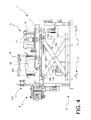
- FIGS. 4 and 5 represent the view of FIG. 3 in different operative positions
- FIG. 6 represents a partial top view of the frame of the labelling machine of the invention.
- FIG. 7A represents a partial perspective view of the labelling machine 1 according to the invention, showing the height and lateral adjusting system of the labelling unit;
- FIG. 7B represents a perspective view of a detail of FIG. 7A ;
- FIG. 8 represents a perspective view of the labelling unit of the labelling machine of the invention.
- FIG. 9 represents a top perspective view according to a horizontal section of the labelling unit of FIG. 8 ;
- FIG. 10 represents a top sectional view of a detail of the cutting drum
- FIG. 11 represents a perspective view of a detail of the cutting blade moving mechanism
- FIG. 12 represents a simplified plan and sectional view of a cutting step of a label with the labelling machine of the invention.
- the labelling machine according to the invention is applicable to a conventional plant 2 for handling containers C.
- the plant 2 schematized in FIG. 1 is a carousel, to which the containers C coming from a previous processing operation, for example, a filling step, are released from a transport system 3 that typically may comprise a conveyor 4 , for example, a screw, and a distribution star 5 .
- the containers after passing in the proximity, of the labelling machine 1 and having been thus labelled, are withdrawn by a second transport system 3 ′ that, similarly to the previous one, may comprise a distribution star 5 ′ and a conveyor 4 ′.
- the labelling machine 1 comprises a frame 6 supporting a platform 7 on which a labelling unit 8 , unwrapping means 9 of a label web N, and a buffer chamber 16 are mounted.
- a series of return rolls 17 mounted idle on the platform 7 , defines the path of the label web N between the unwrapping means 9 and the labelling unit 8 .
- the frame 6 comprises a base 10 provided with feet 11 for the support on a support surface.
- a pantograph system 12 supporting the platform 7 is mounted on the base 10 .
- the pantograph system 12 comprises at least one articulated parallelogram comprising a lower bar 13 a and an upper bar 13 b , between which two articulated arms 14 a , 14 b are arranged.
- two articulated parallelograms one at each side, are arranged.
- the articulated arms 14 a , 14 b are mutually hinged at about the middle of the length thereof, so as to create an X-shaped configuration.
- a first articulated arm 14 a is further hinged at an end on the upper bar 13 b , while the opposite end is slidably constrained at the lower bar 13 a.
- an end of the second arm 14 b is hinged to the lower bar 13 a , while the opposite end is slidably constrained on the upper bar 13 b .
- the lowering or lifting of the pantograph system 12 can be obtained, as shown in the FIGS. 3 (lifted position) and 4 (lowered position). This movement can be obtained by a suitable motorization, or manually.
- the sliding of the upper end of the second arm 14 b in a guide 113 arranged on the upper bar 13 b occurs by acting by rotation on a shaft 114 having a threaded section operatively associated to a lead nut 115 secured to a connection member 116 integral to the second arm 14 b .
- the shaft 114 is rotatably supported on the frame 6 and ends at an end with a conical gear 117 a coupled with a second conical gear 117 b driven by a steering wheel 118 .
- the driven sliding of the upper end of the second arm 14 b in the guide 113 makes it to move away from the upper end of the first arm 14 a and consequently also the mutual moving away of the corresponding lower ends.
- the platform 7 is slidably mounted on the pantograph system 12 .
- the horizontal handling of the platform 7 with respect to the frame 6 may occur with a mechanism completely similar to that described above for the pantograph system 12 and only partially shown in FIG. 6 .
- Such mechanism comprises a steering wheel 119 actuating, through a conical coupling 120 , a shaft 121 having a threaded section operatively connected to a lead nut (not shown) integral to the platform 7 .
- the sliding of the lead nut on the shaft 121 can be obtained, and thus also the movement of the platform 7 , in a direction rather than in the opposite one, according to the fact that the steering wheel 119 is rotated clockwise or counter-clockwise.
- the labelling unit 8 is adjustable both in height and laterally.
- the labelling unit 8 is secured to an adjustable structure 122 , that provides to move the labelling unit 8 both vertically and laterally with respect to the platform 7 .
- An endless screw 123 driven by a crank handle 124 cooperates with a lead nut 125 secured to the adjustable structure 122 , allowing the sliding thereof in a special guide (not shown) according to the directions of the arrow.
- the adjustable structure 122 comprises a plurality of brackets 126 , particularly four brackets, to which the labelling unit 8 is secured.
- the brackets 126 are in turn secured to a movable frame 127 , vertically slidable on a track 128 .
- the movable frame 127 is operatively connected, by a lead nut coupling, to a pair of threaded bars 129 , rotatably supported on the adjustable structure 122 .
- the upper ends of the threaded bars 129 end with corresponding pinions 130 connected by a belt 131 .
- One of the two pinions 130 is actuated by a crank handle 132 , for example, as shown in FIG. 7B , my means of a return mechanism 133 .
- the unwrapping means 9 of the label web N comprise at least one reel-holding roll 15 .
- two rolls 15 are present, so as to minimize the interruptions for replacing the reel.
- Each of the reel-holding rolls 15 is motorized, preferably by a stepper or brushless motor.
- the buffer chamber 16 comprises side walls 16 a and a bottom wall 16 b . Suction means 18 are arranged on the bottom wall 16 b .
- the function of the buffer chamber 16 is to absorb the web N excesses that occur when the label web N is unwrapped at a higher speed than the gripping speed by the labelling unit 8 .
- the labelling unit 8 comprises a supplying roll 19 of the label web N, and a cutting drum 20 providing for both cutting a label E from the label web N and applying it onto the container C.
- the supplying roll 19 is motorized by a motor 22 , to which it is connected by a suitable transmission mechanism 22 a ( FIGS. 7B and 8 ).
- the motor 22 is preferably a stepper or brushless motor.
- the supplying roll 19 also comprises an idle-mounted counter-roll 19 a , which promotes the grip of the supplying roll 19 on the label web N.
- the counter-roll 19 a is opposite the supplying roll 19 , so that the label web N, passing between the counter-roll 19 a and the roll 19 , is compressed against the latter.
- the surface of the supplying roll 19 or that of the counter-roll 19 a or both are made of an elastic material, such as rubber or a synthetic elastomer.
- the outer surface of the supplying roll 19 is texturized so as to have a high grip, for example by a knurling or a honeycomb texture.
- the cutting drum 20 is also motorized by a motor 23 , to which it is connected by suitable transmission mechanism 23 a ( FIGS. 7B and 8 ).
- the motor 23 is preferably a stepper or brushless motor.
- the cutting drum 20 is hollow, and it has externally a suctioned surface 20 a for the label web N.
- the suctioned surface 20 a has a plurality of holes 24 that put it in communication, through ducts 24 a obtained in the body of the cutting drum 20 , with suction means (not shown). In this manner the suctioned surface 20 a is put under vacuum in order to keep the web N in constant contact thereon.
- the cutting drum 20 contains therein cutting means 21 mobile between a retracted position within the cutting drum 20 and an extended position, in which the cutting means project from the suctioned surface 20 a through a vertical slit 25 that is present thereon.
- the cutting means 21 comprise a mobile member 26 hinged on a hinge 27 arranged within the cutting drum 20 and having a first arm 28 a , extending towards the central cavity 31 of the cutting drum 20 , and a second arm 28 b , extending in a direction substantially parallel to a tangent to the suctioned surface 20 a.
- the second arm 28 b comprises a blade support 36 projecting up to the proximity of the vertical slit 25 of the cutting drum 20 , on which blade support 36 a blade 37 is perpendicularly mounted, so as to create an L-shaped configuration. Therefore, the blade 37 is inserted in the vertical slit 25 , without surfacing from the suctioned surface 20 a.
- the blade 37 preferably has a toothed profile, to promote the cutting operation.
- a first drive roller 29 suitable to interact with the profile 20 b of a first cam 32 a
- a second drive roller 30 suitable to interact with the profile of a second cam 32 b are rotatably mounted on the first arm 28 a.
- the cams 32 a and 32 b are integral to a shaft 33 , connected to a motor 35 by a suitable transmission mechanism 34 (see FIGS. 8 and 7B ).
- the first cam 32 a is in the shape of an overturn cup, so as to expose internally the reactive profile for the first drive roller 29 .
- the cams 32 a , 32 b have conjugated profiles so as to produce a swiveling movement of the mobile member 26 about the hinge 27 between said retracted position and said extended position of the cutting means 21 , in which the cutting operation of the label occurs.
- a buffer chamber 38 is arranged between the supplying roll 19 and the cutting drum 20 .
- the buffer chamber 38 has side walls 38 a and a perforated bottom wall 38 b , so as to be in flow communication with a suction chamber 41 , in turn connected to suction means (not visible).
- a return roll 39 for the label web N is mounted idle in front of the buffer chamber 38 .
- the buffer chamber 38 has the following function: when a labelling gap occurs, for example, if the container is not present on a plate of the carousel, or in the case of a displacement, the cutting drum 20 stops or slows down. Vice versa, the supplying roll 19 continues to dispense the label web N, which then builds up in the buffer chamber 38 . In this manner, it is possible to start again at the maximum speed with the labelling of the next container.
- a suctioning loop 40 is arranged downstream of the cutting drum 20 with respect to the forward direction of the container to be labeled.
- the suctioning loop 40 has a first portion 40 a , in the proximity of the cutting drum 20 , having a concave profile; and a second portion 40 b with a profile conjugated to the trajectory of the generatrix of the container to be labeled during transit.
- the portion 40 b will have a curvilinear profile conjugated to the arc of a circle of the carousel subjected to the label transferring operation.
- the portion 40 b will have a rectilinear profile.
- the suctioning loop 40 surface is perforated, thus it is in flow communication with a suction chamber 42 , in turn connected to suction means (not visible).
- the labelling unit 8 is contained between a base plate 43 and a cover plate 44 , which promotes the assembling thereof on or the disassembling thereof from the adjustable structure 122 .
- the operation of the labelling machine 1 is as follows.
- the label web N is unwrapped from the reel mounted on one of the reel-holding rolls 15 , passes on return rolls 17 through the buffer chamber 16 , then through the supplying roll 19 and the counter-roll 19 a .
- both the reel-holding roll 15 and the supplying roll 19 are motorized, and the buffer chamber 16 helps to temporarily house the web N stockpiles that may occur when the unwrapping speed of the web N is higher than the gripping speed by the supplying roll 19 .
- the label web N can be made adhesive in advance at predetermined intervals corresponding to the head and tail portions of the labels to be cut.
- a web without an adhesive will be used, but in this case, means to deposit the glue at predetermined positions will have to be provided along the web path.
- the label web passes on the return roll 39 , and it is then suctioned on the suctioned surface 20 a of the cutting drum 20 .
- the cutting drum 20 is tangent to a container C coming onto the carousel 2 .
- the container C is supported on a small plate that rotates it, whereby the head of the label web N adheres to the surface of the container C and starts to wrap thereon.
- the container C continues its stroke on the carousel 2 .
- the blade 37 exits the vertical slit 25 of the cutting drum 20 and cuts the label E, thus singularizing it.
- the label E tail is kept tensioned and controlled by suctioning of the suctioning loop 40 .
- the cutting drum 20 put in rotation by the motor 23 , has a variable motion profile: in fact, it will have a homokynetic rotation with the rotation of the container to be labeled for an angle of rotation corresponding to the transfer step of the label from the cutting drum 20 to the container until cutting the label E, while it will rotate at a higher peripheral speed along the remaining explementary angle, so as to bring the vertical slit 25 from which the blade 37 exits to the right position for the next cut of a label in the time necessary for the next container arrives to the tangent position.
- the suctioned surface 20 a will slide against the label web N, keeping it adhered by virtue of the suctioning force.
- the movement of the cutting means 21 from the retracted position to the extended cutting position is obtained by the interaction of the second drive roller 30 with the corresponding cam 32 b , while the opposite movement is caused by the interaction of the first drive roller 29 with the first cam 32 a .
- the cams 32 a , 32 b are stationary, while the cutting means 21 rotate integrally with the cutting drum 20 .
- the drive rollers 29 , 30 do intercept the reactive profiles of the cams 32 a , 32 b , rather than vice versa.
- the cams 32 a , 32 b are static if the rotational speed of the cutting drum 20 exceeds a preset value, while they are subjected to a swiveling movement when the rotational speed of the cutting drum 20 is lower than said preset value, as it can be determined empirically by means of operation tests, as a function of the thickness and the type of label to be cut.
- the labelling machine 1 in order to control the complex motion profiles of the machine, particularly of the cutting drum 20 and the cams 32 a , 32 b , according to the various needs required by the different applications, the labelling machine 1 will comprise a drive and control unit.
- the drive and control unit receives signals about the position, the rotational speed, and the acceleration of the motors connected to the reel-holding rolls 15 , the supplying roll 19 , the cutting drum 20 , the shaft 33 of the cams 32 a , 32 b , the carousel 2 , and the motorized plates supporting the containers C, and it transmits control commands to them according to a preset motion law.
- all the motorizations will be provided with an encoder. If the motors 22 , 23 , 35 are brushless motors, they will have an encoder and a programmable controller integrated therein.
- the labelling machine 1 of the invention may also comprise an optical control system of the position of the containers C, the label web N, and the printed portions of the labels E.
- an optical control system may comprise photocells and/or video cameras arranged in suitable positions along the path of the containers C and the label web N or in the handling mechanisms.
- the optical control system provides control signals or images to the drive and control unit, which provides to accordingly change the preset motion law in the case of deviations from a reference standard.
- the fact that the cutting drum 20 is arranged at the release point of the label to the container avoids the management of the singularized label E in a path upstream of the labeling, which instead typically occurs in the prior art labelling machines. This involves a greater compactness of the machine and a greater adaptability thereof to various operative needs.
- the labelling machine according to the invention further has the possibility to adapt to various types and dimensions of container handling plants.
- the pantograph system 12 of the frame 6 and the adjustable structure 122 supporting the labelling unit 8 allow a precise positioning of the labelling unit 8 depending on precise dimensional and type needs both of the transport system from which the containers are brought to the proximity of the cutting drum 20 , and of the same container C and the dimension of the label E to be positioned.
- the container may have various heights and diameters, or the positioning of the label E on the container C can be provided for in different positions.
- the transport system which in the example described above is of the rotating type, consisting in a typical carousel, may have various diameters, or it may also be of the linear type.
- the labelling machine 1 of the invention allows adjusting the labelling unit 8 along all the three axes x, y, and z (as shown in FIG. 2 ).
- a first adjusting level which can be obtained by acting on the pantograph system 12 that adjusts in height the platform 7 on which all the operative members of the machine are mounted
- a second, finer adjusting level which can be obtained by acting on the adjustable structure 122 along the direction z′ ( FIG. 7B ), for the labelling unit 8 only.
Landscapes
- Labeling Devices (AREA)
- Supplying Of Containers To The Packaging Station (AREA)
Applications Claiming Priority (3)
| Application Number | Priority Date | Filing Date | Title |
|---|---|---|---|
| IT001161A ITMI20131161A1 (it) | 2013-07-10 | 2013-07-10 | Gruppo di etichettaggio di contenitori |
| ITMI2013A001161 | 2013-07-10 | ||
| ITMI2013A1161 | 2013-07-10 |
Publications (2)
| Publication Number | Publication Date |
|---|---|
| US20150013914A1 US20150013914A1 (en) | 2015-01-15 |
| US9944423B2 true US9944423B2 (en) | 2018-04-17 |
Family
ID=49118654
Family Applications (1)
| Application Number | Title | Priority Date | Filing Date |
|---|---|---|---|
| US14/327,227 Active 2036-02-29 US9944423B2 (en) | 2013-07-10 | 2014-07-09 | Labelling unit of containers |
Country Status (6)
| Country | Link |
|---|---|
| US (1) | US9944423B2 (fr) |
| EP (1) | EP2824034B1 (fr) |
| CN (1) | CN104276315B (fr) |
| CA (1) | CA2852287C (fr) |
| ES (1) | ES2639298T3 (fr) |
| IT (1) | ITMI20131161A1 (fr) |
Cited By (3)
| Publication number | Priority date | Publication date | Assignee | Title |
|---|---|---|---|---|
| US10233359B2 (en) * | 2015-06-10 | 2019-03-19 | Upm Raflatac Oy | Method for labeling items with labels comprising a clear face layer and a clear adhesive layer |
| US20210292036A1 (en) * | 2020-03-19 | 2021-09-23 | Ilti S.R.L. | Method for feeding linerless labels to a labelling unit and apparatus for feeding linerless labels to the labelling unit |
| US12036688B2 (en) | 2017-05-01 | 2024-07-16 | Avery Dennison Retail Information Services Llc | Stand-alone cutting apparatus |
Families Citing this family (17)
| Publication number | Priority date | Publication date | Assignee | Title |
|---|---|---|---|---|
| US10589889B2 (en) * | 2015-03-04 | 2020-03-17 | Kosme S.R.I. Unipersonale | Labelling machine |
| CN104828323B (zh) * | 2015-05-11 | 2016-08-24 | 广东技术师范学院 | 一种采用普通胶带纸的自动贴管机和自动贴管方法 |
| CN105345396B (zh) * | 2015-12-14 | 2017-12-05 | 中车长江车辆有限公司 | 一种在圆柱面滚压标志的装置及使用该装置的方法 |
| CN106809458A (zh) * | 2016-06-06 | 2017-06-09 | 东莞理工学院 | 一种自动立式圆瓶贴标机 |
| IT201600128413A1 (it) * | 2016-12-20 | 2018-06-20 | Pe Labellers Spa | Macchina e procedimento per l'etichettatura di contenitori. |
| DE102016226178A1 (de) * | 2016-12-23 | 2018-06-28 | Krones Ag | Etikettiervorrichtung und Verfahren zum Aufbringen von Etiketten auf Behältern |
| CN106672360B (zh) * | 2017-01-21 | 2023-09-19 | 中山市华南理工大学现代产业技术研究院 | 撕脱型胶带自动张贴装置 |
| EP3412587A1 (fr) * | 2017-06-09 | 2018-12-12 | Sidel Participations | Module d'étiquetage et machine de traitement de conteneurs associée |
| CN108127264B (zh) * | 2017-12-20 | 2019-08-20 | 重庆军航科技有限公司 | 晶体三极管的印标装置 |
| FR3083780B1 (fr) * | 2018-07-11 | 2020-09-25 | Asidium | Machine et procede de pelliculage des deux faces d'une piece |
| US20200087015A1 (en) * | 2018-09-13 | 2020-03-19 | Avery Dennison Retail Information Services, Llc | Label applicator device |
| IT201900015650A1 (it) * | 2019-09-05 | 2021-03-05 | Sidel Participations Sas | Dispositivo per separare etichette da una striscia di materiale di etichettatura e metodo per applicare etichette ad articoli |
| IT201900015656A1 (it) * | 2019-09-05 | 2021-03-05 | Sidel Participations Sas | Metodo per separare etichette da una striscia di materiale di etichettatura |
| DE102019134642A1 (de) * | 2019-12-17 | 2021-06-17 | Khs Gmbh | Etikettiermaschine zum Etikettieren von Behältern |
| CN111115343B (zh) * | 2020-03-18 | 2021-08-17 | 山东同其数字技术有限公司 | 一种背光板半自动贴胶机 |
| CN113052769B (zh) * | 2020-11-08 | 2021-12-17 | 江苏中科能凯夫空调有限公司 | 基于尺寸辨别的自适应标签选择系统及方法 |
| CN116281371B (zh) * | 2023-04-07 | 2025-05-27 | 东莞纳百防静电材料有限公司 | 带自动贴标功能的除尘膜生产设备及除尘膜的生产方法 |
Citations (6)
| Publication number | Priority date | Publication date | Assignee | Title |
|---|---|---|---|---|
| US5413651A (en) * | 1993-03-23 | 1995-05-09 | B&H Manufacturing Company | Universal roll-fed label cutter |
| US6450230B1 (en) * | 1999-06-24 | 2002-09-17 | S-Con, Inc. | Labeling apparatus and methods thereof |
| US6471802B1 (en) * | 1998-12-07 | 2002-10-29 | Gerro Plast Gmbh | Labeling apparatus and method |
| WO2011027372A1 (fr) | 2009-09-04 | 2011-03-10 | Kosme S.R.L. | Machine d'étiquetage |
| US20110240229A1 (en) * | 2008-12-23 | 2011-10-06 | P.E. Labellers S.P.A. | Machine for labeling by means of labels printed on a ribbon |
| US20120234495A1 (en) * | 2009-12-02 | 2012-09-20 | P.E. Labellers S.P.A. | Labelling machine for labels printed on pre-pasted continuous film |
Family Cites Families (2)
| Publication number | Priority date | Publication date | Assignee | Title |
|---|---|---|---|---|
| JP2729474B2 (ja) * | 1995-07-10 | 1998-03-18 | 光洋自動機株式会社 | ラベリングマシン |
| CN200942896Y (zh) * | 2006-08-24 | 2007-09-05 | 王祖昆 | 曲柄式贴标机 |
-
2013
- 2013-07-10 IT IT001161A patent/ITMI20131161A1/it unknown
-
2014
- 2014-05-13 EP EP14168180.9A patent/EP2824034B1/fr active Active
- 2014-05-13 ES ES14168180.9T patent/ES2639298T3/es active Active
- 2014-05-27 CA CA2852287A patent/CA2852287C/fr active Active
- 2014-07-09 CN CN201410326094.1A patent/CN104276315B/zh active Active
- 2014-07-09 US US14/327,227 patent/US9944423B2/en active Active
Patent Citations (7)
| Publication number | Priority date | Publication date | Assignee | Title |
|---|---|---|---|---|
| US5413651A (en) * | 1993-03-23 | 1995-05-09 | B&H Manufacturing Company | Universal roll-fed label cutter |
| US6471802B1 (en) * | 1998-12-07 | 2002-10-29 | Gerro Plast Gmbh | Labeling apparatus and method |
| US6450230B1 (en) * | 1999-06-24 | 2002-09-17 | S-Con, Inc. | Labeling apparatus and methods thereof |
| US20110240229A1 (en) * | 2008-12-23 | 2011-10-06 | P.E. Labellers S.P.A. | Machine for labeling by means of labels printed on a ribbon |
| WO2011027372A1 (fr) | 2009-09-04 | 2011-03-10 | Kosme S.R.L. | Machine d'étiquetage |
| US20130192766A1 (en) * | 2009-09-04 | 2013-08-01 | Kosme S.R.L. | Labelling machine |
| US20120234495A1 (en) * | 2009-12-02 | 2012-09-20 | P.E. Labellers S.P.A. | Labelling machine for labels printed on pre-pasted continuous film |
Non-Patent Citations (1)
| Title |
|---|
| Italian Search Report for corresponding Italian Patent Application No. MI2013A001161 dated Mar. 12, 2014. |
Cited By (3)
| Publication number | Priority date | Publication date | Assignee | Title |
|---|---|---|---|---|
| US10233359B2 (en) * | 2015-06-10 | 2019-03-19 | Upm Raflatac Oy | Method for labeling items with labels comprising a clear face layer and a clear adhesive layer |
| US12036688B2 (en) | 2017-05-01 | 2024-07-16 | Avery Dennison Retail Information Services Llc | Stand-alone cutting apparatus |
| US20210292036A1 (en) * | 2020-03-19 | 2021-09-23 | Ilti S.R.L. | Method for feeding linerless labels to a labelling unit and apparatus for feeding linerless labels to the labelling unit |
Also Published As
| Publication number | Publication date |
|---|---|
| US20150013914A1 (en) | 2015-01-15 |
| ITMI20131161A1 (it) | 2015-01-11 |
| CN104276315A (zh) | 2015-01-14 |
| EP2824034A1 (fr) | 2015-01-14 |
| CA2852287C (fr) | 2021-07-06 |
| CN104276315B (zh) | 2018-05-11 |
| ES2639298T3 (es) | 2017-10-26 |
| EP2824034B1 (fr) | 2017-06-07 |
| CA2852287A1 (fr) | 2015-01-10 |
Similar Documents
| Publication | Publication Date | Title |
|---|---|---|
| US9944423B2 (en) | Labelling unit of containers | |
| CA2674863C (fr) | Dispositif permettant de former des enveloppes en feuille d'aluminium similaires a des chemises a partir d'une bande droite continue de feuille d'aluminium | |
| US7712291B2 (en) | Film wrapping machine simultaneously utilizing two film carriage assemblies | |
| CN100335371C (zh) | 薄膜输送装置和自动包装装置 | |
| CN101269710B (zh) | 用于将标签贴到包装上的设备和方法 | |
| US9296507B2 (en) | Vacuum transfer element and method for transferring tubular labels | |
| KR20110127061A (ko) | 간헐회전 테이블식 백-필링 포장기 | |
| US20070289665A1 (en) | Container transportation line bottling plants | |
| US10010096B2 (en) | Ice cream sandwich apparatus | |
| US4881357A (en) | Packaging machine for the continuous packaging of products having a variable size | |
| KR101521070B1 (ko) | 스탬핑 스트립용 구동 기기, 이를 구비한 권출 모듈 및 스탬핑 기계 | |
| US4591403A (en) | Pail labeling machine | |
| CN205130506U (zh) | 一种全自动卷筒机 | |
| CN114364609B (zh) | 用于将提手安置在包装材料或包装材料组上的设备和方法 | |
| CN111924224B (zh) | 一种贴带机 | |
| CN105035448A (zh) | 一种适用于多种包装输送线的自动贴标签机 | |
| JP5730906B2 (ja) | フィルム被嵌装置 | |
| KR100915680B1 (ko) | 박스 포장을 위한 비닐 이송 조절장치 및 그를 사용한 박스포장설비 | |
| EP1098815A2 (fr) | Appareil d'etiquetage et procedes s'y rapportant | |
| CN210551422U (zh) | 一种包装材料切割装置的切刀往复驱动机构 | |
| TR2023019663A2 (tr) | Tam Otomatik Çikolata Paketleme Makinesi | |
| HUE027069T2 (en) | Apparatus and method for placing self-adhesive labels on the wall of containers | |
| ITBO20080603A1 (it) | Apparecchiatura per l'etichettatura di contenitori | |
| US20210078744A1 (en) | Method and Apparatus for Gripping and Holding Dispensing Elements, Having a Flange and a Screw Cap, for Subsequent Application onto Packages | |
| ITMO20080096A1 (it) | Macchina etichettatrice. |
Legal Events
| Date | Code | Title | Description |
|---|---|---|---|
| AS | Assignment |
Owner name: SMILAB S.R.L., ITALY Free format text: ASSIGNMENT OF ASSIGNORS INTEREST;ASSIGNOR:ZACCHE', VANNI;REEL/FRAME:033289/0099 Effective date: 20140514 |
|
| STCF | Information on status: patent grant |
Free format text: PATENTED CASE |
|
| FEPP | Fee payment procedure |
Free format text: ENTITY STATUS SET TO UNDISCOUNTED (ORIGINAL EVENT CODE: BIG.); ENTITY STATUS OF PATENT OWNER: LARGE ENTITY |
|
| MAFP | Maintenance fee payment |
Free format text: PAYMENT OF MAINTENANCE FEE, 4TH YEAR, LARGE ENTITY (ORIGINAL EVENT CODE: M1551); ENTITY STATUS OF PATENT OWNER: LARGE ENTITY Year of fee payment: 4 |
|
| AS | Assignment |
Owner name: SMI S.P.A., ITALY Free format text: ASSIGNMENT OF ASSIGNORS INTEREST;ASSIGNOR:SMILAB S.R.L.;REEL/FRAME:059156/0675 Effective date: 20220111 |
|
| MAFP | Maintenance fee payment |
Free format text: PAYMENT OF MAINTENANCE FEE, 8TH YEAR, LARGE ENTITY (ORIGINAL EVENT CODE: M1552); ENTITY STATUS OF PATENT OWNER: LARGE ENTITY Year of fee payment: 8 |