US9946035B2 - Fiber optic connector - Google Patents
Fiber optic connector Download PDFInfo
- Publication number
- US9946035B2 US9946035B2 US15/260,305 US201615260305A US9946035B2 US 9946035 B2 US9946035 B2 US 9946035B2 US 201615260305 A US201615260305 A US 201615260305A US 9946035 B2 US9946035 B2 US 9946035B2
- Authority
- US
- United States
- Prior art keywords
- connector
- barrel projection
- puller
- front body
- barrel
- Prior art date
- Legal status (The legal status is an assumption and is not a legal conclusion. Google has not performed a legal analysis and makes no representation as to the accuracy of the status listed.)
- Active
Links
Images


Classifications
-
- G—PHYSICS
- G02—OPTICS
- G02B—OPTICAL ELEMENTS, SYSTEMS OR APPARATUS
- G02B6/00—Light guides; Structural details of arrangements comprising light guides and other optical elements, e.g. couplings
- G02B6/24—Coupling light guides
- G02B6/36—Mechanical coupling means
- G02B6/38—Mechanical coupling means having fibre to fibre mating means
- G02B6/3807—Dismountable connectors, i.e. comprising plugs
- G02B6/3873—Connectors using guide surfaces for aligning ferrule ends, e.g. tubes, sleeves, V-grooves, rods, pins, balls
- G02B6/3874—Connectors using guide surfaces for aligning ferrule ends, e.g. tubes, sleeves, V-grooves, rods, pins, balls using tubes, sleeves to align ferrules
- G02B6/3878—Connectors using guide surfaces for aligning ferrule ends, e.g. tubes, sleeves, V-grooves, rods, pins, balls using tubes, sleeves to align ferrules comprising a plurality of ferrules, branching and break-out means
- G02B6/3879—Linking of individual connector plugs to an overconnector, e.g. using clamps, clips, common housings comprising several individual connector plugs
-
- G—PHYSICS
- G02—OPTICS
- G02B—OPTICAL ELEMENTS, SYSTEMS OR APPARATUS
- G02B6/00—Light guides; Structural details of arrangements comprising light guides and other optical elements, e.g. couplings
- G02B6/24—Coupling light guides
- G02B6/36—Mechanical coupling means
- G02B6/38—Mechanical coupling means having fibre to fibre mating means
- G02B6/3807—Dismountable connectors, i.e. comprising plugs
- G02B6/3869—Mounting ferrules to connector body, i.e. plugs
- G02B6/3871—Ferrule rotatable with respect to plug body, e.g. for setting rotational position ; Fixation of ferrules after rotation
-
- G—PHYSICS
- G02—OPTICS
- G02B—OPTICAL ELEMENTS, SYSTEMS OR APPARATUS
- G02B6/00—Light guides; Structural details of arrangements comprising light guides and other optical elements, e.g. couplings
- G02B6/24—Coupling light guides
- G02B6/36—Mechanical coupling means
- G02B6/38—Mechanical coupling means having fibre to fibre mating means
- G02B6/3807—Dismountable connectors, i.e. comprising plugs
- G02B6/381—Dismountable connectors, i.e. comprising plugs of the ferrule type, e.g. fibre ends embedded in ferrules, connecting a pair of fibres
- G02B6/3818—Dismountable connectors, i.e. comprising plugs of the ferrule type, e.g. fibre ends embedded in ferrules, connecting a pair of fibres of a low-reflection-loss type
- G02B6/3821—Dismountable connectors, i.e. comprising plugs of the ferrule type, e.g. fibre ends embedded in ferrules, connecting a pair of fibres of a low-reflection-loss type with axial spring biasing or loading means
-
- G—PHYSICS
- G02—OPTICS
- G02B—OPTICAL ELEMENTS, SYSTEMS OR APPARATUS
- G02B6/00—Light guides; Structural details of arrangements comprising light guides and other optical elements, e.g. couplings
- G02B6/24—Coupling light guides
- G02B6/36—Mechanical coupling means
- G02B6/38—Mechanical coupling means having fibre to fibre mating means
- G02B6/3807—Dismountable connectors, i.e. comprising plugs
- G02B6/3869—Mounting ferrules to connector body, i.e. plugs
- G02B6/387—Connector plugs comprising two complementary members, e.g. shells, caps, covers, locked together
-
- G—PHYSICS
- G02—OPTICS
- G02B—OPTICAL ELEMENTS, SYSTEMS OR APPARATUS
- G02B6/00—Light guides; Structural details of arrangements comprising light guides and other optical elements, e.g. couplings
- G02B6/24—Coupling light guides
- G02B6/36—Mechanical coupling means
- G02B6/38—Mechanical coupling means having fibre to fibre mating means
- G02B6/3807—Dismountable connectors, i.e. comprising plugs
- G02B6/3873—Connectors using guide surfaces for aligning ferrule ends, e.g. tubes, sleeves, V-grooves, rods, pins, balls
- G02B6/3874—Connectors using guide surfaces for aligning ferrule ends, e.g. tubes, sleeves, V-grooves, rods, pins, balls using tubes, sleeves to align ferrules
- G02B6/3878—Connectors using guide surfaces for aligning ferrule ends, e.g. tubes, sleeves, V-grooves, rods, pins, balls using tubes, sleeves to align ferrules comprising a plurality of ferrules, branching and break-out means
-
- G—PHYSICS
- G02—OPTICS
- G02B—OPTICAL ELEMENTS, SYSTEMS OR APPARATUS
- G02B6/00—Light guides; Structural details of arrangements comprising light guides and other optical elements, e.g. couplings
- G02B6/24—Coupling light guides
- G02B6/36—Mechanical coupling means
- G02B6/38—Mechanical coupling means having fibre to fibre mating means
- G02B6/3807—Dismountable connectors, i.e. comprising plugs
- G02B6/3873—Connectors using guide surfaces for aligning ferrule ends, e.g. tubes, sleeves, V-grooves, rods, pins, balls
- G02B6/3885—Multicore or multichannel optical connectors, i.e. one single ferrule containing more than one fibre, e.g. ribbon type
-
- G—PHYSICS
- G02—OPTICS
- G02B—OPTICAL ELEMENTS, SYSTEMS OR APPARATUS
- G02B6/00—Light guides; Structural details of arrangements comprising light guides and other optical elements, e.g. couplings
- G02B6/24—Coupling light guides
- G02B6/36—Mechanical coupling means
- G02B6/38—Mechanical coupling means having fibre to fibre mating means
- G02B6/3807—Dismountable connectors, i.e. comprising plugs
- G02B6/3887—Anchoring optical cables to connector housings, e.g. strain relief features
-
- G—PHYSICS
- G02—OPTICS
- G02B—OPTICAL ELEMENTS, SYSTEMS OR APPARATUS
- G02B6/00—Light guides; Structural details of arrangements comprising light guides and other optical elements, e.g. couplings
- G02B6/24—Coupling light guides
- G02B6/36—Mechanical coupling means
- G02B6/38—Mechanical coupling means having fibre to fibre mating means
- G02B6/3807—Dismountable connectors, i.e. comprising plugs
- G02B6/389—Dismountable connectors, i.e. comprising plugs characterised by the method of fastening connecting plugs and sockets, e.g. screw- or nut-lock, snap-in, bayonet type
- G02B6/3893—Push-pull type, e.g. snap-in, push-on
Definitions
- the disclosed subject matter relates generally to data cabling, and, in particular, to fiber optic connectors
- LC fiber optic connectors for termination and connectivity of fiber optic cables.
- the small form factor of these LC connectors allows a large number of fiber optic cables to be connected in high density arrays, such as those found in fiber optic patch panels used in data centers.
- Duplexed LC connectors together house two optical fibers each of which is terminated on a respective ferrule that protrude from the front of the duplexed connectors, thereby providing termination and connectivity for a transmit fiber and a receive fiber.
- the small form factor of the LC connector whether used as a single connector (“simplex”) or as a duplexed pair—affords a number of advantages, particularly in high density environment. There are, however, a number of functional and perceptual issues inherent in conventional LC connector designs.
- the minimal spacing between adjacent LC connectors makes it difficult to both insert the LC connector into, and disconnect it from, its corresponding port in an adapter or module disposed in a patch panel.
- reversing the polarity in the field of patch cables pre-terminated to duplexed LC connectors can be a cumbersome task, requiring the duplexed LC connector assembly to be disassembled and the terminated ferrules within the assembly to be physically swapped before reassembling the assembly.
- polarity reversal of duplexed LC connectors creates a risk of tangling or twisting the optical fibers when the ferrules are swapped, potentially damaging the fibers.
- users cannot easily identify the current polarity configuration for a given patch cable without unplugging and disassembling the connector.
- Embodiments described herein relate to an improved fiber optic connector design that provides a number of advantages over current LC connector designs.
- Embodiments of the fiber optic connector described herein incorporate features that facilitate easy access to selected fiber cable connectors within high density environments, while maintaining a form factor having a low profile conducive to such high density applications.
- the fiber optic connector assemblies described herein employ a relatively small number of component parts, yielding a rigid and reliable construction while lowering manufacturing costs relative to connector designs requiring a larger number of components.
- Unique barrel features used in both duplex and paired simplex versions of the connector assembly facilitate fast and easy polarity reversal with little or no risk of twisting or damaging optical fibers in the process.
- a long-tail puller component can also be added to the connector assembly to provide ready access to the connector within congested installations.
- the connector maintains a low profile that reduces the risk of catching on adjacent cables or enclosure edges when pulled through congested fiber paths.
- FIG. 1 is an orthographic view of the components of an example duplex fiber optic connector with unibody housing.
- FIG. 2 is a detailed view of a unibody housing.
- FIG. 3 is an orthographic front view of an example unibody housing with ferrule assemblies installed in respective barrel projections.
- FIG. 4 is a detailed rear view of a unibody housing of a fiber optic connector.
- FIG. 5 is an orthographic view of an example front body of a fiber optic connector.
- FIG. 6A is a side view and a front view of a front body of a fiber optic connector housing having a substantially square profile.
- FIG. 6B is a side view and a front view of an example front housing of a fiber optic connector having a chamfered front face.
- FIG. 6C is a side view, a front view, and an orthogonal view of an example front body of a fiber optic connector having chamfered or rounded corners on its front face.
- FIG. 7 is an orthogonal view of an example puller for a duplex fiber optic connector.
- FIG. 8A is an orthogonal view of an assembled fiber optic connector with unibody housing including a puller.
- FIG. 8B is a top view of an assembled fiber optic connector with unibody housing including a puller.
- FIG. 9A is a front view of an assembled fiber optic connector with unibody housing.
- FIG. 9B is a front view of an assembled fiber optic connector with unibody housing depicting rotation of the front bodies.
- FIG. 10 is an orthographic view of the components of an example paired simplex fiber optic connector with duplex clip.
- FIG. 11 is an orthographic view of a rear body of a paired simplex fiber optic connector.
- FIG. 12 is an orthogonal view of an example duplex clip for a paired simplex fiber optic connector.
- FIG. 13 is a rear view of two rear bodies held together by duplex clip.
- FIG. 14A is a top view of an assembled paired simplex connector with a duplex clip.
- FIG. 14B is a top view of an assembled paired simplex connector including a puller with a duplex clip.
- FIG. 15 is an orthographic view of a puller used for a paired simplex connector.
- FIG. 16A is an orthographic rear view of a paired simplex connector assembly with a duplex clip without a puller.
- FIG. 16B is an orthographic rear view of a paired simplex connector with a duplex clip including a puller.
- FIG. 17 is a front view of a paired simplex connector with a duplex clip including a puller with the front bodies removed.
- FIG. 18 is an orthographic view of a paired simplex connector with a duplex clip including a puller.
- FIG. 19 is a side view of a paired simplex connector with a duplex clip including a puller.
- FIGS. 20A-20F are orthographic views of a paired simplex connector with a duplex clip and puller illustrating a sequence for reversing the polarity of the connector.
- FIG. 21 is a side view of an example high density patching installation comprising a number of stacked adapters.
- FIG. 22 is a side view of an example simplex fiber optic connector.
- FIG. 23 is a flowchart of an example methodology for assembling a duplex fiber optic connector.
- FIG. 24A is a first part of a flowchart of an example methodology for assembling a paired simplex fiber optic connector assembly.
- FIG. 24B is a second part of the flowchart of the example methodology for assembling a paired simplex fiber optic connector assembly.
- FIG. 25 is a flowchart of an example methodology for reversing the polarity of a duplex connector assembly or a paired simplex connector assembly.
- duplex type connector for use with duplex fiber optic cables (e.g., round duplex or other types of duplex cables) as well as in a paired simplex connector assembly that allows two simplex connectors to be clipped together to yield a sturdy duplex type connector. Both types of assemblies are described in detail below.
- FIG. 1 is an orthographic view of the components of an example duplex LC connector assembly according to one or more embodiments of this disclosure.
- the components of the duplexed LC connector assembly are separated in FIG. 1 to provide a view of the individual components and their relationships to one another.
- the duplexed LC connector assembly includes a unibody housing 116 having two hollow barrel projections 114 on its front side (note that only one barrel projection 114 is visible in FIG. 1 , since the second barrel projection is concealed by front body 102 b installed thereon).
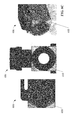
- FIG. 2 is a detailed view of the unibody housing 116 .
- the barrel projections 114 are hollow through their respective lengths, each providing a passage from the inner chamber of the unibody housing 116 to the outside of the connector.
- a step or groove 208 is formed around the base of each barrel projection 114 . In various embodiments, this groove may completely traverse the circumference of the barrel projection 114 , or may traverse a portion of the circumference. These grooves 208 are used to affix front bodies 102 on the barrel projections 114 in a rotatable manner, as will be described in more detail below.
- a coil spring 112 and corresponding ferrule assembly 106 is installed through the front opening of each barrel projection 114 , such that a rear tip of the ferrule assembly 106 resides within the coil of the spring 112 , thereby spring-loading the ferrule assembly 106 .
- cuts 214 may be formed along the front portion of each barrel projection 114 , extending from the front opening of the barrel projection to a point along its length, to allow a degree of expansion while installing the ferrule assembly.
- FIG. 3 is an orthographic front view of an example embodiment of the unibody housing 116 with the ferrule assemblies 106 installed in the respective barrel projections 114 .
- the inner surface of the front opening of each barrel projection 114 comprises a number of flat surfaces arranged to form a hexagonal profile designed to mate with the hexagonal shape of the ferrule holder 306 of ferrule assembly 106 .
- the flat inner surfaces of the barrel opening and the corresponding surfaces of ferrule holder 306 prevent the ferrule assembly 106 (and the optical fibers connected thereto) from twisting inside the unibody housing 116 .
- the profile of the barrel projection's inner surface is depicted as being hexagonal in FIG. 3 , it is to be appreciated that any suitable geometric shape can be used as the basis for the front opening of the barrel projections 114 without departing from the scope of one or more embodiments of this disclosure
- the unibody housing 116 also includes a crimp core 122 on its rear side that provides a rear opening into the unibody housing 116 , as can be seen more clearly in FIG. 4 , which is a detailed rear view of the unibody housing 116 .
- Two optical fibers of a duplex fiber cable can enter the inner chamber of the unibody housing 116 through this rear opening.
- two fiber passages 204 a and 204 b are formed in the inner chamber of unibody housing 116 , each of the two fiber passages 204 a and 204 b leading from the rear opening (crimp core 122 ) to one of the barrel projections.
- the two optical fibers that enter the unibody housing 116 via crimp core 122 are routed through these two fiber passages 204 —one fiber per passage—and connected to the rear ferrule connector of ferrule assembly 106 , thereby providing a signal connection between the ferrules and their corresponding optical fibers.
- unibody housing 116 can include two adhesive needle channels 118 a and 118 b located on the rear side of the unibody housing opposite the two barrel projections 114 , as can be seen in FIGS. 2 and 4 .
- These adhesive needle channels 118 serve as passage ways through which a manufacturer can insert an adhesive injection needle during fabrication of the connector in order to inject epoxy or other adhesive material on the joint between the fiber optic cable and the ferrule assembly 106 .
- lid 120 which is attached to the main unibody housing via strap 202 at this stage—can be affixed to the top of the unibody housing 116 , thereby enclosing the fiber optic cables and rear ends of the ferrule assemblies 106 within the unibody housing.
- projections 206 on the inside surface of lid 120 are inserted into the adhesive needle channels 118 , thereby closing the channels 118 and preventing debris from entering the unibody housing 116 .
- the strap 202 can be removed by the manufacturer prior to distribution of the duplexed LC connector assembly.
- FIG. 1 depicts an assembly comprising a crimp sleeve 124 and heat shrink tubing 126 , which can act as a sheath for the incoming cable.
- the assembly can also include a tapered boot 128 that can be slid over heat shrink tubing 126 and the crimp sleeve 124 for additional protection.
- FIG. 1 depicts front body 102 b as being installed over its corresponding barrel projection, while front body 102 a has been removed from its corresponding barrel projection 114 to provide a view of the component parts).
- Each front body 102 is hollow and comprises a front opening that is oriented such that, when the front body is fully installed on barrel projection 114 , the forward spring force applied by the spring 112 causes the ferrule of ferrule assembly 106 to project through the front opening of the front body 102 , while the remainder of the ferrule assembly 106 and the spring 112 are housed within the chamber formed by the front body 102 and the barrel projection 114 .
- the ferrule assembly 106 is spring-loaded against the front body 102 , such that the front body keeps the ferrule and spring contained within the hollow portion of the barrel projection 114 while the front body is mounted over the barrel projection.
- FIG. 5 is an orthographic view of an example front body 102 .
- Front body 102 mounts over a barrel projection 114 by sliding the rear of the front body 102 over the front of the barrel projection 114 such that the front of the barrel projection enters the rear opening 508 of front body 102 .
- Cuts 504 are formed on the front body 102 , traversing from the rear edge of the front body to a point along the length of the front body. These cuts 504 allow a degree of expandability when installing the front body 102 over the barrel projection 114 .
- the example illustrated in FIG. 5 depicts only two cuts 504 on opposite left and right sides of the body, thereby splitting the rear opening 508 into two sections. However, some embodiments may also include only one cut, or may include third and fourth cuts 504 on the top and bottom sides of the front body 102 , thereby yielding a design having more than two sections or fewer than two sections.
- each section of rear opening 508 comprises a raised ridge 502 designed to reside in groove 208 of the barrel projection 114 .
- the raised ridges 502 latch into groove 208 of the barrel projection 114 , holding the front body 102 in place on the unibody housing 116 .
- the interaction of these raised ridges 502 with groove 208 also facilitates rotation of the front body 102 about the barrel projection 114 .
- Front body 102 also includes an elastic latch 506 on its top surface that serves to latch the connector within an adapter when plugged into a patch panel or other device.
- the upward spring force of the cantilevered latch 506 causes latching surfaces 510 on the latch to remain engaged with corresponding latching features on the adapter. Applying a downward pressure on the latch 506 causes the latching surfaces 510 to disengage from the latching features of the adapter, thereby allowing the connector to be removed.
- Latch 506 also includes two recessed areas 512 within which the t-bar of long-tail puller 108 (see FIG. 1 ) resides when the puller 108 is added to the duplexed LC connector assembly, as will be described in more detail below.
- the design of the unibody housing 116 and front body 102 offers a number of advantages over conventional LC connector designs. For one, inclusion of the barrel projections 114 as formations on the unibody housing 116 over which the front bodies 102 are installed yields a connector design requiring fewer parts than are typically used for duplexed LC connector assemblies. For example, many LC connector designs require two front bodies that connect to respective rear bodies, which in turn are connected to a uniboot housing. By contrast, the unibody housing and front body designs described above eliminate the need for a rear body component, thereby lowering manufacturing costs by reducing part count.
- the interaction of the front body 102 and the barrel projection 114 allows the front body to rotate about the barrel projection 114 independently of the ferrule assembly (that is, without causing a corresponding rotation of the ferrule assembly), which allows the polarity of the duplexed LC connector assembly to be easily reversed in the field with little or no risk of twisting or damaging the optical fibers inside the unibody housing 116 , and without the need to open the connector housing. Since this polarity reversal feature is implemented in a connector design having a compact form factor, a puller 108 can also be mounted to the connector without expanding the duplexed LC connector assembly's size profile to a degree that interferes with adjacent connectors in high density connector installations.
- front body 102 can include a number of other features that improve user experience.
- the front edges of front body 102 can be chamfered to promote ease of insertion into a data port.
- FIG. 6A depicts a side view and a front view of a front body 604 having a substantially square profile.
- FIG. 6B depicts a side and front view of an example front body 102 having a chamfered front face according to one or more embodiments of the present disclosure.
- the four edges of the front face are chamfered, resulting in angled surfaces 602 around the front opening of front body 102 , in contrast to the squared edges of front body 604 .
- This design affords the user a greater degree of alignment tolerance when inserting the connector into a square fiber optic adapter port, since the angled surfaces 602 allow room for error when aligning the front of the connector with the entrance of the adapter.
- This feature can be particularly useful when the user is attempting to plug the connector into a fiber optic adapter located outside the user's field of view (e.g., an adapter located in the rear of a panel facing a wall, or that is obscured by other equipment), requiring the user to align the connector with the adapter purely by touch and with no visual guidance.
- FIG. 6C depicts side, front, and orthogonal views of another example front body 606 having chamfered or rounded corners 608 on its front face. These chamfered corners 608 serve a similar function to the angled surfaces 602 of front body 102 using an alternative design that produces a more rounded front face.
- FIG. 7 is an orthogonal view of an example puller 108 according to one or more embodiments.
- Puller 108 includes a sleeve 110 and a t-bar 704 connected together by an arm.
- Sleeve 110 has a cut along its bottom so that the sleeve can be slipped over the fiber optic cable and moved forward onto boot 128 and into position on the duplexed LC connector assembly.
- a protrusion 702 located below t-bar 704 is designed to insert into a corresponding recess 212 in unibody housing 116 (see FIG. 2 ).
- FIG. 8A is an orthogonal view of the assembled duplex fiber optic connectors with unibody housing 116 , including puller 108 .
- Applying a pull force on the sleeve 110 of puller 108 can cause a least a portion of the pull force to be translated to the t-bar 704 residing in recessed areas 512 of the front body latches 506 (see FIG. 5 ), causing a substantially equal distribution of pull force between the two front bodies 102 a , 102 b and assisting in removal of the front bodies 102 a , 102 b from their corresponding ports in a duplex adapter.
- puller 108 can improve physical access to the duplexed LC connector assembly in high density installations to facilitate insertion and removal of the assembly from the adapter.
- the compact form factor of the puller 108 also prevents it from physically interfering with adjacent connectors in such environments.
- the rear end sleeve 110 portion of the puller 108 includes no sharp features that could catch on cables or wires as the duplexed LC connector is being pulled through a congested environment.
- FIG. 8B is a top view of the assembled duplex fiber optic connector. Note that the left and right sides of t-bar 704 reside within the recessed areas 512 formed in latches 506 of the front bodies 102 (see FIG. 5 ), ensuring that a pulling force applied to the puller 108 is distributed substantially equally to each side of t-bar 704 and thus equally to the two latches 506 of the duplexed LC connectors. Also, as can be seen in the view of FIG.
- one or more embodiments of the unibody housing 116 can be marked with identification markings 802 that distinguish between the top side and bottom side of the unibody housing 116 , allowing users to easily identify whether the polarity of the optical fibers with the duplex patch cable terminated to the duplexed LC connectors has been reversed. This is described in more detail below in connection with the polarity reversal technique made possible by embodiments of the subject connector design.
- FIG. 9A is a front view of the assembled duplex fiber optic connector.
- protrusion 702 of puller 108 resides in a corresponding recess of the unibody housing 116 between the two fiber passages 204 .
- the physical relationships between the front bodies 102 , the barrel projections 114 of unibody housing 116 , and the ferrule assemblies 106 allow the front bodies 102 a , 102 b to be rotated about the unibody housing 116 independently of the ferrule assemblies 106 , as illustrated in the front view of FIG. 9B , which depicts front bodies 102 a , 102 b semi-transparently.
- FIG. 9B depicts front bodies 102 a , 102 b semi-transparently.
- front body 102 a is depicted as having been rotated 180 degrees, while front body 102 b is in the process of being rotated.
- the raised ridges 502 along the inside rim of the front body's rear opening 508 remain seated within the groove 208 at the base of the barrel projection 114 (see FIG. 2 ), holding the front body 102 on the barrel projection 114 while allowing the front body to rotate freely about the barrel projection. Since the barrel projection 114 physically separates the front body 102 and the ferrule holder 306 (see FIG.
- this rotation is carried out without a corresponding rotation of the ferrule assembly 106 (which is further prevented from rotating by the hexagonal shape of the inner chamber of barrel projection 114 , as described above in connection with FIG. 3 ).
- This design facilitates a simple process for reversing the polarity of a fiber optic patch cable associated with the duplexed LC connectors, as will be described in more detail below.
- duplexed fiber optic connector assembly suitable for duplex fiber optic cables—e.g., round duplex or other duplex cable types—wherein two optical fibers are enclosed in a common cable that enters the crimp core 122 on the rear side of the unibody housing 116 , and wherein the two optical fibers are separatedly routed inside the unibody housing 116 within separate fiber passages 204 a and 204 b.
- FIG. 10 is an orthographic view of the components of an example paired simplex fiber optic connectors according to one or more embodiments of this disclosure. These paired simplex embodiments incorporate several of the same components used in the duplexed unibody housing version described above.
- the front bodies 102 , ferrule assembly 106 , and spring 112 are similar to the corresponding components of the duplexed unibody housing assembly.
- the unibody housing 116 is replaced with two rear bodies 1002 a and 1002 b , corresponding to the respective front bodies 102 a and 102 b .
- rear body 1002 b is depicted as being connected to its corresponding front body 102 b
- rear body 1002 a is depicted as being separated from its corresponding front body 102 a to provide a view of the ferrule assembly 106 and spring 112 that reside inside the front body/rear body assembly.
- FIG. 11 is an orthographic view of a rear body 1002 .
- the rear body 1002 used in the paired simplex connector comprises a barrel projection 1102 having a similar construction to that used in the unibody housing 116 of the duplex design. That is, barrel projection 1102 is hollow throughout its length and includes a front opening 1104 having a hexagonal profile designed to mate with the hexagonal shape of the ferrule holder of ferrule assembly 106 (although other geometric profiles for the front opening 1104 are also within the scope of one or more embodiments of this disclosure). Barrel projection 1102 also includes two or more cuts 1114 that extend from the front opening 1104 to a point part way down the length of the barrel projection.
- a step or groove 1112 is formed at the base of barrel projection 1102 , and either fully or partially traverses the circumference off the barrel projection 1102 .
- the groove 1112 is configured to receive the raised ridges 502 along rim of the rear opening 508 of front body 102 (see FIG. 5 ).
- a crimp core 1110 is located on the rear side of rear body 1002 and, as shown in FIG. 10 , is designed to mate with a crimp sleeve 1014 that, together with heat shrink tubing 1010 and boot 1012 , connect a simplex optical cable to the rear body 1002 .
- FIG. 10 depicts crimp sleeve 1014 , heat shrink tubing 1010 , and boot 1012 as the means for affixing an optical cable to the rear body 1002 , it is to be appreciated that other means for attaching the cable to the rear body 1002 are within the scope of one or more embodiments of this disclosure.
- Spring 112 and ferrule assembly 106 are inserted into the barrel projection 1102 of rear body 1002 via front opening 1104 .
- the optical fiber of a simplex cable attached to the crimp core 1110 enters the rear body 1002 and is attached to the rear connection point of ferrule assembly 106 , thereby establishing a communicative connection between the optical fiber and the ferrule assembly.
- front body 102 is slid over the barrel projection 1102 of rear body 1002 in a manner similar to installation of the front body 102 over barrel projection 114 of the unibody housing 116 .
- the raised ridges 502 along the rim of the front body's rear opening 508 latch (see FIG.
- duplex clip 1008 can be used to join two rear bodies 1002 together in a rigid duplex arrangement, and two front bodies 102 can be mounted on the respective two rear bodies 1002 .
- Duplex clip 1008 comprises an elongated plate 1208 , with each of the left and right sides of the plate 1208 having a pair of opposing rails 1202 located along the top and bottom edges of the plate 1208 .
- the rails 1202 begin at the front edge of the plate 1208 and extend part way along the top and bottom edges toward the rear edge of the plate 1208 .
- the two rails on a given side of the plate 1208 are spaced away from the plate and oriented such that the two rails face each other. That is, the rails along the top edge face downward, while the rails along the bottom face upward.
- the spacing of the rails 1202 from the plate 1208 is set to correspond to a thickness of two side plates 1106 located on the left and right sides of the rear body 1002 .
- These side plates 1106 can be seen in FIG. 11 .
- grooves 1108 are defined behind the top and bottom edges of the side plates 1106 .
- the rails 1202 of duplex clip 1008 are designed to slide into these grooves 1108 from the rear side of rear body 1002 .
- the side plates 1106 of rear body 1002 reside within the spaces 1204 defined by the top and bottom rails 1202 of duplex clip 1008 .
- FIG. 13 is a rear view of two rear bodies 1002 being held together by duplex clip 1008 .
- rails 1202 of duplex clip 1008 reside in the grooves 1108 behind the top and bottom edges of the side plates 1106 of the rear bodies 1002 , effectively holding the two rear bodies 1002 firmly in place by clasping their inner surfaces.
- FIG. 14A is a top view of the assembled paired of simplex LC connectors, comprising the duplex clip 1008 , rear bodies 1002 a and 1002 b held together by the duplex clip 1008 , and front bodies 102 a and 102 b mounted to the barrel projections of the rear bodies 1002 .
- the ferrule assemblies 106 and springs reside within the chamber formed by the front and rear bodies, with the front tips of the ferrules protruding through the front openings of the front bodies 102 .
- Duplex clip 1008 is designed to hold the two simplex LC connector assemblies such that the spacing between the two simplex LC connectors conforms to a standard duplex spacing, allowing the paired simplex LC connector assemblies to be plugged into a duplex adapter.
- the relatively large area of contact between the duplex clip 1008 and the rear bodies' side plates 1106 prevents the two simplex LC connector assemblies from bending toward or away from each other to an excessive degree, thereby reliably maintaining this parallel arrangement.
- this design improves user experience by ensuring that the paired simplex LC connector assembly reliably aligns with a mating duplex adapter and maintains the parallel configuration between the duplexed fiber optic signal paths.
- FIG. 14B is another top view of the paired simplex LC connector assembly that adds a puller 1004 .
- Puller 1004 includes a t-bar 1402 connected to a cable anchor 1006 by an arm.
- FIG. 15 is an orthographic view of the puller 1004 used for the paired simplex LC connector assembly according to one or more embodiments.
- puller 1004 While having a broadly similar form factor to the puller 108 used in the duplex LC connector assembly with unibody housing 116 described above, a number of design aspects of puller 1004 are adapted for use with the paired simplex LC connector assembly with duplex clip 1008 .
- the cable anchor 1006 comprises two concave surfaces 1007 a and 1007 b adapted to accommodate the two parallel simplex cables that enter each of the paired simplex LC connectors, respectively, as can be seen in FIGS. 16A and 16B .
- FIG. 16A is an orthographic rear view of the paired simplex connector assembly with the puller 1004 omitted.
- duplex clip 1008 holds two rear bodies 1002 in a parallel orientation, and two front bodies 102 are attached to the barrel projections 1102 of rear bodies 1002 , enclosing the ferrule assemblies 106 and springs 112 within the resulting assemblies (see FIG. 10 ).
- two simplex optical cables 1602 are attached to crimp cores 1110 on the rear sides of the rear bodies 1002 using crimp sleeves 1014 , and boots 1012 are slid over the crimp sleeves 1014 .
- the optical fibers of the respective optical cables 1602 enter the rear bodies 1002 via crimp cores 1110 and attach to the ferrule assemblies within the front bodies 102 a , 102 b and rear bodies 1002 a , 1002 b.
- FIG. 16B is an orthographic rear view of the paired simplex LC connector assembly with puller 1004 attached.
- the cable anchor 1006 of the puller resides between the two simplex fiber optic cables (e.g., between the two boots 1012 ), with the concave surfaces 1007 a , 1007 b of the cable anchor 1006 accommodating the two simples fiber optic cables.
- FIG. 17 is a front view of the paired simplex LC connector assembly including puller 1004 , with the front bodies 102 a , 102 b removed for clarity. As can be seen in FIG.
- puller 1004 includes three protrusions 1502 a , 1502 b , 1504 below t-bar 1402 that reside within corresponding grooves 1214 a , 1214 b , 1212 formed by the two puller rails 1210 of the duplex clip 1008 .
- the grooves 1214 a , 1214 b , 1212 defined by the two puller rails 1210 include a square groove 1212 between the two rails 1210 , a first notched groove 1214 a on the left side of the left-hand puller rail 1210 , and a second notched groove 1214 b on the right side of the right-hand puller rail 1210 .
- the left and right notched grooves 1214 a , 1214 b on the clip 1008 are configured to receive corresponding V-shaped rails on the left and right protrusions 1502 a , 115 b of the puller 1004 .
- This design allows the puller 1004 to be mounted on the duplex clip 1008 by aligning the rails of the left and right protrusions 1502 a , 1502 b with the corresponding notched grooves 1214 a , 1214 b of the clip 1008 , and sliding the t-bar 1402 of the puller 1004 over the duplex clip 1008 , either from the front or rear of the duplex clip 1008 .
- puller 1004 also includes a middle protrusion 1504 that resides in the square groove 1212 between the two puller rails 1210 of the clip 1008 .
- This middle protrusion 1504 presents a stop for the puller 1004 operating within the square groove 1212 between the two puller rails 1210 of clip 1008 .
- This middle protrusion stop prevents the puller 1004 from separating from the duplexed LC connector assembly when pulled rearward, and also prevents the t-bar 1402 of puller 1004 from slipping rearward, and out of engagement with, recessed areas 512 disposed in latches 506 of front bodies 102 a , 102 b (see FIGS. 5 and 10 ).
- puller rails 1210 are also located on the bottom of duplex clip 1008 , yielding a symmetrical profile. Mirroring the puller rails 1210 on both the top and bottom of the clip 1008 assists in the polarity reversal technique to be described in more detail below in connection with FIGS. 20A-20F .
- FIG. 18 is an orthographic view of the paired simplex LC connector assembly including the puller 1004 .
- the t-bar 1402 provides an easily accessible means for removing the paired simplex LC connector assembly from a duplex adapter.
- the left and right sides of t-bar 1402 reside within the recessed areas 512 formed in latches 506 of the front bodies 102 a , 102 b (see FIGS. 5 and 10 ), ensuring that a pulling force applied both sides of t-bar 1402 is distributed substantially equally to the two simplex LC connectors of the paired LC connector assembly.
- FIG. 19 is a side view of the paired simplex LC connector assembly including the puller 1004 .
- the puller 1004 is designed such that the addition of the puller 1004 to the paired LC connector assembly does not introduce additional height to the paired LC connector assembly's vertical profile. That is, the top surface of the puller 1004 does not extend upward past the top surface of the latches 506 of front bodies 102 a , 102 b . This ensures that the puller 1004 will not interfere with adjacent connectors or cables in high density connectivity installations.
- FIGS. 20A-20F are orthographic views of the paired simplex LC connector assembly illustrating a sequence for reversing the polarity of the fiber optic circuitry.
- 20A-20F illustrate polarity reversal for the circuitry of a paired simplex LC connector assembly with duplex clip 1008 , it is to be appreciated that a similar operation can be used to reverse the polarity for the duplex LC connector assembly with the unibody housing 116 described above.
- FIG. 20A is an orthographic rear view of the paired simplex LC connector assembly, which is used to connect two simplex fiber optic cables 2002 a and 2002 b to a duplex adapter.
- cable 2002 a is connected to the left side of the paired simplex LC connector assembly while cable 2002 b is connected to the right side.
- cable 2002 a will be plugged into the left port of the duplex adapter while cable 2002 b will be plugged into the right port of the duplex adapter.
- the following steps can be carried out.
- the front bodies 102 a , 102 b are rotated 180 degrees about the barrel projections 114 of rear bodies 1002 a , 1002 b (or unibody housing 116 ).
- the front bodies 102 a , 102 b are rotated 180 degrees about the barrel projections 114 of rear bodies 1002 a , 1002 b (or unibody housing 116 ).
- the front bodies 102 a , 102 b are mounted in a rotatable manner on the barrel projections 114 , and the ferrule assemblies 106 are installed inside the barrel projections 114 in a fixed manner, the front bodies 102 a , 102 b can be rotated without causing a corresponding rotation of the ferrule assemblies 106 , thereby preventing twisting of the ferrule assemblies 106 and the optical fibers disposed therein.
- the paired simplex LC connectors of the assemblies are is in an upside-down orientation vis-á-vis the duplex clip 1008 (or unibody housing 116 ) compared to the starting position.
- the puller 1004 is removed from the paired simplex LC connector assembly.
- this can be achieved by sliding the puller 1004 forward, away from cables 2002 a , 2002 b , so that the t-bar 1402 of puller 104 can be disengaged from the recessed areas 512 in the latches 506 of front bodies 102 a , 102 b , and thereby disconnecting the protrusions 1502 a , 1502 b , 1504 of puller 1004 from the puller rails 1210 on top of the duplex clip 1008 .
- the puller 1004 can then be pulled backward toward the cables 2002 a , 2002 b to facilitate removal of the puller 1004 from the paired simplex LC connector assembly. Since the cable anchor 1006 of puller 1004 is held between the two cables 2002 a , 2002 b , the risk of the puller 1004 falling from the paired simplex LC connector assembly during this step in the polarity reversal process is minimized.
- the puller 1004 is then moved to the opposite side of the paired simplex LC connector assembly, as shown in FIG. 20D . At this stage, the puller 1004 is not yet reattached to the duplex clip 1008 .
- the entire paired simplex LC connector assembly is then rotated, as shown in FIG. 20E .
- this rotation causes cables 2002 a and 2002 b to be reversed in position vis-á-vis the duplex clip 1008 (or unibody housing 116 ), while also causing the paired simplex LC connector assembly to be reoriented in the right-side-up position.
- the puller 1004 is reattached to the duplex clip 1008 by aligning the protrusions 1502 a , 1502 b , 1504 of puller 1004 with the puller rails 1210 on the duplex clip 1008 and sliding the puller 1004 backward, causing the front of the puller 1004 to engage with the clip 1008 .
- puller rails 1210 on the duplex clip 1008 to which the puller 1004 is attached during this step are those that were located on the bottom of the clip in FIG. 20A , but which are now in the top position due to the rotation during polarity reversal shown in FIG. 20E . Since the same puller rails 1210 are located on both the top and bottom of the duplex clip 1008 , the polarity reversal can be achieved without disconnecting the clip 1008 from the rear bodies 1002 .
- attachment of the puller 108 to the duplexed LC connector assembly is achieved by inserting protrusion 702 of puller 108 (see FIG. 7 ) into a corresponding recess 212 in the unibody housing 116 (see FIGS. 2, 9A, 9B ), where this recess 212 is accessible on both the top and bottom sides of the unibody housing 116 .
- cables 2002 a and 2002 b have reversed position relative to the position of cables 2002 a and 2002 b shown in FIG. 20A , such that cable 2002 b will be plugged into the left port of a duplex adapter, and cable 2002 a will be plugged into the right port.
- the LC connectors of the assemblies can include visual features that assist a user in identifying the current polarity configuration of the assembled connectors.
- the top surface of the unibody housing 116 of the duplexed connector can be marked with identifying characters that distinguish the top of the duplexed connector from the bottom of the duplexed connector.
- the top of the duplexed connector is embossed with a letter “B” on the left side, and a letter “A” on the right side. Seeing these letters embossed on top of the duplexed connector can indicate to the user that the duplexed connector is currently configured for its default, or as-built, polarity.
- the reverse side of unibody housing 116 may be embossed with a different combination of characters—e.g., the letter “A” on both the left and right sides—which become oriented on the top side of the duplexed connector when the polarity is reversed. Seeing this alternative pair of characters can indicate to the user that the duplexed connector has been reconfigured for polarity reversal. It is to be appreciated that other distinguishing characters or marks can be used on the top and bottom surfaces of the duplexed connector without departing from the scope of one or more embodiments of this disclosure.
- the procedure outlined above in connection with FIGS. 20A-20F allows a user to quickly and easily reverse the polarity of the duplexed connector in the field without twisting or damaging the optical fibers connected to the ferrules inside the connector housings, and without requiring the user to disassemble the connector housing in order to access the ferrule assemblies housed therein.
- the design of the duplex and paired simplex connectors described herein allow this polarity reversal feature to be implemented even when a puller is included as part of the connector assembly, since the puller can be easily relocated to the appropriate side of the connector as needed.
- FIG. 21 is a side view of an example high density connectivity installation comprising a number of stacked adapters 2102 , each adapter comprising a row of duplexed data ports into which duplexed or paired simplex connectors 2104 can be inserted.
- the vertical profile of the connector design described herein is low enough to remain within the profile dimensions of the adapters 2102 . Their low vertical profile allows the connectors 2104 to be installed in high density connectivity applications without interference between adjacent connectors.
- the latch 506 of the front body 102 can comprise a long arch that extends nearly to the body of the connector, as shown in FIG. 22 .
- the arch of the latch 506 extends such that the space 2202 between the end of the latch 506 and the connector housing is small, while the arch is flexible enough to allow a user to bend the latch 506 downward sufficiently to disengage the latch from a mated adapter. Keeping this space 2202 small reduces the risk of cables becoming snagged by the latch 506 as the connector is pulled through a high density connectivity environment.
- duplexed and paired simplex connectors described herein incorporate a number of design features that address a number of functional and perceptual issues that arise in fiber optic patching applications.
- the relatively small number of parts required for the connector assemblies described herein can reduce manufacturing costs while providing a more rigid structure relative to connectors that incorporate a greater number of components.
- the connectors described herein allow users to quickly and easily reverse the polarity of the connectors and cabling in the field (e.g., from crossed to straight-through, or vice versa) without twisting or entangling the optical fibers housed within the connectors, and without opening the connector housing.
- This polarity reversal feature is implemented in a connector design that also allows for installation of a puller (e.g., puller 108 or 1004 ) that facilitates easy access to the connector in congested connectivity environments for ease of connector insertion and removal from corresponding duplex adapters.
- a puller e.g., puller 108 or 1004
- the chamfered front edges of the front bodies 102 of the connectors can improve the ease with which the connectors are inserted into a fiber adapter, particularly in low visibility, or close, areas where precise manual alignment between the connector and a corresponding adapter is not easily achieved.
- FIGS. 23-25 illustrate various methodologies in accordance with one or more embodiments of the subject application. While, for purposes of simplicity of explanation, the one or more methodologies shown herein are described as a series of steps, it is to be understood and appreciated that the subject innovation is not limited by the order of steps, as some steps may, in accordance therewith, occur in a different order and/or concurrently with other steps from that shown and described herein. For example, those skilled in the art will understand and appreciate that a methodology could alternatively be represented as a series of interrelated states or events, such as in a state diagram. Moreover, not all illustrated steps may be required to implement a methodology in accordance with the innovation.
- interaction diagram(s) may represent methodologies, or methods, in accordance with the subject disclosure when disparate entities enact disparate portions of the methodologies.
- two or more of the disclosed example methods can be implemented in combination with each other, to accomplish one or more features or advantages described herein.
- FIG. 23 illustrates an example methodology 2300 for assembling a duplexed fiber optic connector according to one or more embodiments described herein.
- a spring and a ferrule assembly are installed in a hollow barrel projection formed on a front side of a unibody housing, the barrel projection forming a passage into an inner chamber of the unibody housing and comprising a groove that traverses all or part of the circumference of the barrel projection.
- a front body is installed over the barrel projection, causing the tip of the ferrule assembly to protrude through a front opening of the front body.
- the front body comprises at least one ridge along an inner rim or edge of the rear opening, and the at least one ridge resides in the groove of the barrel projection while the front body is installed over the barrel projection, such that the front body is rotatable about the barrel projection independently of the ferrule assembly
- the ferrule assembly is connected to an optical fiber inside the inner chamber of the unibody housing, the optical fiber entering the inner chamber via an opening on the rear side of the unibody housing.
- Steps 2302 - 2306 can be repeated for a second barrel projection formed on the front side of the unibody housing, a second front body, a second ferrule assembly, and a second spring, thereby completing the duplexed assembly for two optical fibers of an incoming duplex fiber optic cable.
- a lid is closed or installed on the unibody housing, enclosing the connections made at 2306 within the housing.
- a puller is installed on the unibody housing, the puller having at least one protrusion that resides in a corresponding recess in the unibody housing.
- FIGS. 24A and 24B are two parts of an example methodology 2400 for assembling paired simplex fiber optic connectors according to one or more embodiments described herein.
- a first spring and a first ferrule assembly are installed in a hollow barrel projection formed on a front side of a first rear body, the barrel projection comprising a groove that traverses all or part of a circumference of the barrel projection.
- a first front body is installed over the barrel projection, causing the front tip of the first ferrule assembly to protrude through a front opening of the first front body.
- the first front body comprises at least one ridge along an inner edge or rim of a rear opening, and the at least one ridge resides in the groove of the barrel projection while the first front body is installed over the barrel projection, such that the first front body is rotatable about the barrel projection independently of the first ferrule assembly.
- the first ferrule assembly is connected to a first optical fiber inside the first rear body, the first optical fiber entering the first rear body via an opening on the rear side of the first rear body.
- a first crimp sleeve is installed on a first crimp core located on the rear side of the first rear body.
- a second spring, a second ferrule assembly, a second front body, and a second crimp sleeve are installed on a second rear body, and a second optical fiber is connected to the second ferrule assembly inside the second rear body.
- a left side of the first rear body is mounted to a right side of a clip such that top and bottom rails on the right side of the clip reside in corresponding grooves on the top left edge and bottom left edge of the first rear body.
- a right side of the second rear housing is mounted to a left side of the clip such that top and bottom rails on the left side of the clip reside in corresponding grooves on the top right edge and bottom right edge of the second rear body.
- first and second boots are slid forward to rear walls of the first and second rear bodies, respectively.
- a puller is installed on the assembly that results from implementing steps 2402 - 2416 , the puller having at least one protrusion that resides in a corresponding groove of the clip.
- FIG. 25 illustrates an example methodology 2500 for reversing the polarity of a duplexed connector or a paired simplex connector according to one or more embodiments of this disclosure.
- the methodology begins at step 2502 a , where a puller is removed from a top surface of the connector.
- a first front body of the duplexed connector is rotated approximately 180 degrees about a unibody housing of the duplexed connector.
- the first front body may be mounted on one of two barrel projections of the unibody housing in a manner that allows the front body to be rotated about the barrel projection.
- a second front body of the duplex connector is also rotated approximately 180 degrees about the unibody housing.
- the methodology begins at step 2502 b , where a puller is removed from a top surface of the connector.
- a first front body of the paired simplex connector is rotated approximately 180 degrees about a first rear body of the paired simplex connector.
- a second front body of the paired simplex connector is also rotated approximately 180 degrees about a second rear body of the paired simplex connector.
- the first and second rear bodies may be connected in a parallel orientation using a duplex clip to form the paired simplex connector.
- the methodology moves to step 2508 , where the connector is flipped such that the bottom surface of the connector now faces upward, and reversed vis-á-vis the duplexing unibody housing or pairing clip compared to the starting position.
- the puller is attached to the now upward-facing surface of the connector, and the polarity reversal is complete.
Landscapes
- Physics & Mathematics (AREA)
- General Physics & Mathematics (AREA)
- Optics & Photonics (AREA)
- Mechanical Coupling Of Light Guides (AREA)
Priority Applications (10)
| Application Number | Priority Date | Filing Date | Title |
|---|---|---|---|
| US15/260,305 US9946035B2 (en) | 2016-04-11 | 2016-09-08 | Fiber optic connector |
| CA3255593A CA3255593A1 (fr) | 2016-04-11 | 2016-10-07 | Connecteur optique rotatif |
| CA3020696A CA3020696C (fr) | 2016-04-11 | 2016-10-07 | Connecteur optique rotatif |
| MX2018012417A MX2018012417A (es) | 2016-04-11 | 2016-10-07 | Conector de fibra óptica giratorio. |
| EP24155091.2A EP4339670A3 (fr) | 2016-04-11 | 2016-10-07 | Connecteur optique rotatif |
| EP16898857.4A EP3430450B1 (fr) | 2016-04-11 | 2016-10-07 | Connecteur optique rotatif |
| PCT/US2016/055876 WO2017180181A1 (fr) | 2016-04-11 | 2016-10-07 | Connecteur optique rotatif |
| US15/381,071 US10156683B2 (en) | 2016-04-11 | 2016-12-15 | Polarity identification for polarity reversing duplex unibody connectors |
| PCT/US2017/020150 WO2017180257A1 (fr) | 2016-04-11 | 2017-03-01 | Identification de polarité pour des connecteurs monocorps duplex à inversion de polarités |
| MX2023009552A MX2023009552A (es) | 2016-04-11 | 2018-10-10 | Conector de fibra optica giratorio. |
Applications Claiming Priority (2)
| Application Number | Priority Date | Filing Date | Title |
|---|---|---|---|
| US201662321145P | 2016-04-11 | 2016-04-11 | |
| US15/260,305 US9946035B2 (en) | 2016-04-11 | 2016-09-08 | Fiber optic connector |
Related Child Applications (1)
| Application Number | Title | Priority Date | Filing Date |
|---|---|---|---|
| US15/381,071 Continuation-In-Part US10156683B2 (en) | 2016-04-11 | 2016-12-15 | Polarity identification for polarity reversing duplex unibody connectors |
Publications (2)
| Publication Number | Publication Date |
|---|---|
| US20170293089A1 US20170293089A1 (en) | 2017-10-12 |
| US9946035B2 true US9946035B2 (en) | 2018-04-17 |
Family
ID=59998030
Family Applications (2)
| Application Number | Title | Priority Date | Filing Date |
|---|---|---|---|
| US15/260,305 Active US9946035B2 (en) | 2016-04-11 | 2016-09-08 | Fiber optic connector |
| US15/481,039 Active US10139572B2 (en) | 2016-04-11 | 2017-04-06 | Duplex fiber optic components suitable for polarity reversal |
Family Applications After (1)
| Application Number | Title | Priority Date | Filing Date |
|---|---|---|---|
| US15/481,039 Active US10139572B2 (en) | 2016-04-11 | 2017-04-06 | Duplex fiber optic components suitable for polarity reversal |
Country Status (5)
| Country | Link |
|---|---|
| US (2) | US9946035B2 (fr) |
| EP (2) | EP4339670A3 (fr) |
| CA (2) | CA3020696C (fr) |
| MX (2) | MX2018012417A (fr) |
| WO (2) | WO2017180181A1 (fr) |
Cited By (32)
| Publication number | Priority date | Publication date | Assignee | Title |
|---|---|---|---|---|
| US10191230B2 (en) * | 2017-01-30 | 2019-01-29 | Senko Advanced Components, Inc. | Optical connectors with reversible polarity |
| US10281669B2 (en) | 2017-07-14 | 2019-05-07 | Senko Advance Components, Inc. | Ultra-small form factor optical connectors |
| US10444444B2 (en) | 2017-01-30 | 2019-10-15 | Senko Advanced Components, Inc. | Remote release tab connector assembly |
| WO2020076868A1 (fr) * | 2018-10-10 | 2020-04-16 | Senko Advanced Components, Inc | Connecteur de fibres optiques à polarités multiples comportant un ensemble de gaines de câble duplex |
| US10705300B2 (en) | 2017-07-14 | 2020-07-07 | Senko Advanced Components, Inc. | Small form factor fiber optic connector with multi-purpose boot assembly |
| US10718911B2 (en) | 2017-08-24 | 2020-07-21 | Senko Advanced Components, Inc. | Ultra-small form factor optical connectors using a push-pull boot receptacle release |
| US10866371B2 (en) | 2016-06-28 | 2020-12-15 | Senko Advanced Components, Inc. | Adapter system for multi-fiber mechanical transfer type ferrule |
| US10921531B2 (en) | 2018-09-12 | 2021-02-16 | Senko Advanced Components, Inc. | LC type connector with push/pull assembly for releasing connector from a receptacle using a cable boot |
| US10921530B2 (en) | 2018-09-12 | 2021-02-16 | Senko Advanced Components, Inc. | LC type connector with push/pull assembly for releasing connector from a receptacle using a cable boot |
| US10935736B2 (en) * | 2019-02-25 | 2021-03-02 | Leviton Manufacturing Co., Inc. | Rotary clip for duplex polarity change |
| US11002923B2 (en) | 2017-11-21 | 2021-05-11 | Senko Advanced Components, Inc. | Fiber optic connector with cable boot release having a two-piece clip assembly |
| US11073664B2 (en) | 2018-08-13 | 2021-07-27 | Senko Advanced Components, Inc. | Cable boot assembly for releasing fiber optic connector from a receptacle |
| US11086087B2 (en) | 2018-09-12 | 2021-08-10 | Senko Advanced Components, Inc. | LC type connector with clip-on push/pull tab for releasing connector from a receptacle using a cable boot |
| US11112566B2 (en) | 2018-03-19 | 2021-09-07 | Senko Advanced Components, Inc. | Removal tool for removing a plural of micro optical connectors from an adapter interface |
| US11175464B2 (en) | 2018-11-25 | 2021-11-16 | Senko Advanced Components, Inc. | Open ended spring body for use in an optical fiber connector |
| US11187857B2 (en) | 2018-07-15 | 2021-11-30 | Senko Advanced Components, Inc. | Ultra-small form factor optical connector and adapter |
| US11314024B2 (en) | 2019-06-13 | 2022-04-26 | Senko Advanced Components, Inc. | Lever actuated latch arm for releasing a fiber optic connector from a receptacle port and method of use |
| US11340406B2 (en) | 2019-04-19 | 2022-05-24 | Senko Advanced Components, Inc. | Small form factor fiber optic connector with resilient latching mechanism for securing within a hook-less receptacle |
| US11409056B2 (en) * | 2020-03-27 | 2022-08-09 | Afl Ig Llc | Optical fiber connectors and methods of connecting optical fibers |
| US11467354B2 (en) | 2019-07-23 | 2022-10-11 | Senko Advanced Components, Inc. | Ultra-small form factor receptacle for receiving a fiber optic connector opposing a ferrule assembly |
| US11573381B2 (en) | 2020-03-27 | 2023-02-07 | Afl Telecommunications Llc | Optical fiber connectors and methods of connecting optical fibers |
| US11579379B2 (en) | 2019-03-28 | 2023-02-14 | Senko Advanced Components, Inc. | Fiber optic adapter assembly |
| US11806831B2 (en) | 2018-11-21 | 2023-11-07 | Senko Advanced Components, Inc. | Fixture and method for polishing fiber optic connector ferrules |
| US11822133B2 (en) | 2017-07-14 | 2023-11-21 | Senko Advanced Components, Inc. | Ultra-small form factor optical connector and adapter |
| US11934017B2 (en) | 2021-03-02 | 2024-03-19 | Corning Research & Development Corporation | Polarity changeable optical connector |
| US20240168243A1 (en) * | 2017-12-19 | 2024-05-23 | Us Conec Ltd. | Mini duplex connector with push-pull polarity mechanism and carrier |
| US12001064B2 (en) | 2017-07-14 | 2024-06-04 | Senko Advanced Components, Inc. | Small form factor fiber optic connector with multi-purpose boot |
| US12038613B2 (en) | 2019-03-28 | 2024-07-16 | Senko Advanced Components, Inc. | Behind-the-wall optical connector and assembly of the same |
| US12455418B2 (en) | 2023-04-20 | 2025-10-28 | Corning Research & Development Corporation | Duplex fiber optic assembly with repositionable latch housing for polarity reversal, and related methods |
| US12461320B2 (en) | 2022-08-29 | 2025-11-04 | Corning Research & Development Corporation | Optical connector with rotatable boot and related methods |
| US12523821B2 (en) | 2021-04-08 | 2026-01-13 | Commscope Technologies Llc | Telecommunications connector with latch release mechanism |
| US12560765B2 (en) | 2022-03-02 | 2026-02-24 | Corning Research & Development Corporation | Polarity changeable optical connector |
Families Citing this family (13)
| Publication number | Priority date | Publication date | Assignee | Title |
|---|---|---|---|---|
| JP6173629B1 (ja) * | 2016-06-29 | 2017-08-02 | 株式会社精工技研 | 二連式の光コネクタプラグ及び二連式の光コネクタプラグの極性変換方法並びにフェルール研磨方法 |
| TWM548279U (zh) * | 2017-03-03 | 2017-09-01 | 光聖科技(寧波)有限公司 | 高密度光纖接頭 |
| US10895697B2 (en) * | 2017-04-14 | 2021-01-19 | Hewlett Packard Enterprise Development Lp | Optical adapters |
| US10620384B2 (en) | 2017-05-25 | 2020-04-14 | Senko Advanced Components, Inc. | Adjustable polarity fiber optic connector assemblies with push-pull tabs |
| JP7027781B2 (ja) * | 2017-10-04 | 2022-03-02 | 住友電気工業株式会社 | 光コネクタおよび光接続構造 |
| US11237342B2 (en) | 2018-06-28 | 2022-02-01 | Senko Advanced Components, Inc. | Adjustable polarity fiber optic connector assembly with shortened rotatable boot assembly |
| JP7536465B2 (ja) * | 2019-02-25 | 2024-08-20 | サンワ エレクトロニクス ユーエスエー コーポレイション | 可逆光コネクタ、並びに関連するデバイス、システム及び方法 |
| WO2021011651A1 (fr) * | 2019-07-17 | 2021-01-21 | Commscope Technologies Llc | Connecteur de fibre optique avec tube époxy à flotteur axial |
| US11340405B2 (en) * | 2019-09-13 | 2022-05-24 | US Conec, Ltd | Multi-ferrule angled polished connector with simplified polarity reversal |
| BR112022007939A2 (pt) * | 2019-11-20 | 2022-07-12 | Senko Advanced Components Inc | Conector de fibra óptica de polaridade reversível |
| TWI747170B (zh) * | 2020-02-20 | 2021-11-21 | 立佳興業股份有限公司 | 光學連接器 |
| TWI734532B (zh) * | 2020-02-21 | 2021-07-21 | 立佳興業股份有限公司 | 光學連接器及其光學連接器模組 |
| US12332486B2 (en) * | 2020-05-21 | 2025-06-17 | Us Conec Ltd. | Ferrule seating features for a fiber optic connector |
Citations (33)
| Publication number | Priority date | Publication date | Assignee | Title |
|---|---|---|---|---|
| US4611887A (en) | 1983-02-24 | 1986-09-16 | Amp Incorporated | Fiber optic connector assembly and wall outlet thereof |
| US5123071A (en) | 1990-03-09 | 1992-06-16 | Amp Incorporated | Overconnector assembly for a pair of push-pull coupling type optical fiber connectors |
| US5293581A (en) | 1993-04-16 | 1994-03-08 | Alcoa Fujikura Ltd. | Flexible connector assembly for fiber optics |
| US5528712A (en) * | 1995-02-06 | 1996-06-18 | Belenkiy; Yuriy | Duplex connector |
| US5579425A (en) | 1995-08-30 | 1996-11-26 | Lucent Technologies Inc. | Anti-snag duplex connector |
| US5727101A (en) | 1995-10-06 | 1998-03-10 | Siecor Corporation | Monolithic ferrule for receiving and positioning multiple optical fibers and an optical fiber connector incorporating same |
| US6250817B1 (en) | 1999-10-19 | 2001-06-26 | Lucent Technologies Inc. | Device that attaches to the boot of an optical fiber simplex connector to provide the connector with anti-snagging and/or polarity identification features |
| US6357934B1 (en) | 2000-01-27 | 2002-03-19 | Lucent Technologies Inc. | Optical fiber boot for a connector that provides anti-snagging and polarity identification |
| US6409392B1 (en) | 1999-10-19 | 2002-06-25 | Fitel Usa Corp. | Duplex clip for clipping two optical fiber simplex connectors together to form a duplex connector |
| US6435732B1 (en) | 2000-09-28 | 2002-08-20 | Sumitomo Wiring Systems, Ltd. | Optical connector |
| US6511230B1 (en) | 2000-02-04 | 2003-01-28 | Panduit Corp. | Fiber optic connection system |
| US6672898B2 (en) | 2000-04-18 | 2004-01-06 | Krone Gmbh | Duplex connectors for optical fiber plug-in connectors |
| US6744939B2 (en) * | 2002-05-20 | 2004-06-01 | Fitel Usa Corp. | Polarization maintaining optical fiber connector and method of tuning (PM connector) |
| US6918704B2 (en) | 2003-01-30 | 2005-07-19 | Panduit Corp. | Tunable fiber optic connector |
| US7178990B2 (en) | 2003-08-25 | 2007-02-20 | Panduit Corp. | Reversible fiber optic stub fiber clamping mechanism |
| US20070047877A1 (en) | 2005-08-26 | 2007-03-01 | Tyco Electronics Corporation | Duplex style fiber optic connector interface assembly |
| US7189008B2 (en) | 2004-12-20 | 2007-03-13 | Molex Incorporated | Indexed optical fiber connector |
| US7712970B1 (en) | 2009-01-12 | 2010-05-11 | Alliance Fiber Optic Products Co., Ltd. | Detachable fiber optic connector |
| WO2010099141A1 (fr) | 2009-02-27 | 2010-09-02 | Corning Cable Systems Llc | Ensembles à fibres optiques duplex appropriés pour une inversion de polarité et procédés apparentés |
| US20120099822A1 (en) | 2010-10-22 | 2012-04-26 | Panduit Corp. | Optical Communication Connector |
| CN102749683A (zh) | 2012-07-13 | 2012-10-24 | 安费诺光纤技术(深圳)有限公司 | Sc 联合角套连接器套件 |
| CN102749682A (zh) | 2012-07-13 | 2012-10-24 | 安费诺光纤技术(深圳)有限公司 | 可换极性的sc 联合角套连接器套件 |
| US20120308183A1 (en) | 2011-06-06 | 2012-12-06 | Panduit Corp. | Duplex Clip Assembly for Fiber Optic Connectors |
| CN103091793A (zh) | 2012-10-10 | 2013-05-08 | 富波有限公司 | 光缆连接器装置、光缆组件及改变光纤极性的方法 |
| US20140050443A1 (en) | 2012-08-14 | 2014-02-20 | Jhih-Ping LEE | Reconfigurable polarity detachable connector assembly |
| TWM474924U (zh) | 2013-09-27 | 2014-03-21 | Fiberon Technologies Inc | 具空間角位置換之光學連接器 |
| US8727638B2 (en) | 2011-12-21 | 2014-05-20 | Alliance Fiber Optic Products Co., Ltd. | Fiber channel-inter changeable fiber optic connector |
| US20140169727A1 (en) | 2011-05-04 | 2014-06-19 | The Siemon Company | Fiber Optic Connector With Polarity Change |
| US8801301B2 (en) | 2010-03-16 | 2014-08-12 | Ofs Fitel, Llc | Simplex connectors for multicore optical fiber cables |
| US20140270636A1 (en) | 2013-03-15 | 2014-09-18 | Leviton Manufacturing Co., Inc. | Efficient fiber usage within pre-terminated fiber devices |
| WO2015103783A1 (fr) | 2014-01-13 | 2015-07-16 | Tyco Electronics (Shanghai) Co., Ltd. | Connecteur de fibres optiques |
| US9207410B2 (en) | 2013-12-23 | 2015-12-08 | Alliance Fiber Optic Products, Inc. | Optical fiber connector assembly |
| US9625658B1 (en) | 2016-04-12 | 2017-04-18 | Jyh Eng Technology Co., Ltd. | Communication connector with alterable polarity |
Family Cites Families (3)
| Publication number | Priority date | Publication date | Assignee | Title |
|---|---|---|---|---|
| US5394497A (en) | 1994-02-22 | 1995-02-28 | The Whitaker Corporation | Captivated fiber optic connector |
| ES2395358B1 (es) * | 2011-02-08 | 2014-04-25 | Tyco Electronics Corporation | Conectador de acción única |
| EP2802911A4 (fr) * | 2012-01-12 | 2015-08-26 | 3M Innovative Properties Co | Connecteur de fibres optiques duplex pouvant être monté sur site et comportant des éléments d'épissure mécanique |
-
2016
- 2016-09-08 US US15/260,305 patent/US9946035B2/en active Active
- 2016-10-07 EP EP24155091.2A patent/EP4339670A3/fr active Pending
- 2016-10-07 MX MX2018012417A patent/MX2018012417A/es unknown
- 2016-10-07 CA CA3020696A patent/CA3020696C/fr active Active
- 2016-10-07 EP EP16898857.4A patent/EP3430450B1/fr active Active
- 2016-10-07 CA CA3255593A patent/CA3255593A1/fr active Pending
- 2016-10-07 WO PCT/US2016/055876 patent/WO2017180181A1/fr not_active Ceased
-
2017
- 2017-04-06 US US15/481,039 patent/US10139572B2/en active Active
- 2017-04-07 WO PCT/US2017/026486 patent/WO2017180452A1/fr not_active Ceased
-
2018
- 2018-10-10 MX MX2023009552A patent/MX2023009552A/es unknown
Patent Citations (44)
| Publication number | Priority date | Publication date | Assignee | Title |
|---|---|---|---|---|
| US4611887A (en) | 1983-02-24 | 1986-09-16 | Amp Incorporated | Fiber optic connector assembly and wall outlet thereof |
| US5123071A (en) | 1990-03-09 | 1992-06-16 | Amp Incorporated | Overconnector assembly for a pair of push-pull coupling type optical fiber connectors |
| US5293581A (en) | 1993-04-16 | 1994-03-08 | Alcoa Fujikura Ltd. | Flexible connector assembly for fiber optics |
| US5528712A (en) * | 1995-02-06 | 1996-06-18 | Belenkiy; Yuriy | Duplex connector |
| US5579425A (en) | 1995-08-30 | 1996-11-26 | Lucent Technologies Inc. | Anti-snag duplex connector |
| US5727101A (en) | 1995-10-06 | 1998-03-10 | Siecor Corporation | Monolithic ferrule for receiving and positioning multiple optical fibers and an optical fiber connector incorporating same |
| US6250817B1 (en) | 1999-10-19 | 2001-06-26 | Lucent Technologies Inc. | Device that attaches to the boot of an optical fiber simplex connector to provide the connector with anti-snagging and/or polarity identification features |
| US6409392B1 (en) | 1999-10-19 | 2002-06-25 | Fitel Usa Corp. | Duplex clip for clipping two optical fiber simplex connectors together to form a duplex connector |
| US6357934B1 (en) | 2000-01-27 | 2002-03-19 | Lucent Technologies Inc. | Optical fiber boot for a connector that provides anti-snagging and polarity identification |
| US6511230B1 (en) | 2000-02-04 | 2003-01-28 | Panduit Corp. | Fiber optic connection system |
| US6672898B2 (en) | 2000-04-18 | 2004-01-06 | Krone Gmbh | Duplex connectors for optical fiber plug-in connectors |
| US6435732B1 (en) | 2000-09-28 | 2002-08-20 | Sumitomo Wiring Systems, Ltd. | Optical connector |
| US6744939B2 (en) * | 2002-05-20 | 2004-06-01 | Fitel Usa Corp. | Polarization maintaining optical fiber connector and method of tuning (PM connector) |
| US6918704B2 (en) | 2003-01-30 | 2005-07-19 | Panduit Corp. | Tunable fiber optic connector |
| US7178990B2 (en) | 2003-08-25 | 2007-02-20 | Panduit Corp. | Reversible fiber optic stub fiber clamping mechanism |
| US7189008B2 (en) | 2004-12-20 | 2007-03-13 | Molex Incorporated | Indexed optical fiber connector |
| US20070047877A1 (en) | 2005-08-26 | 2007-03-01 | Tyco Electronics Corporation | Duplex style fiber optic connector interface assembly |
| US7712970B1 (en) | 2009-01-12 | 2010-05-11 | Alliance Fiber Optic Products Co., Ltd. | Detachable fiber optic connector |
| WO2010099141A1 (fr) | 2009-02-27 | 2010-09-02 | Corning Cable Systems Llc | Ensembles à fibres optiques duplex appropriés pour une inversion de polarité et procédés apparentés |
| US20100220961A1 (en) * | 2009-02-27 | 2010-09-02 | De Jong Michael | Duplex Fiber Optic Assemblies Suitable for Polarity Reversal and Methods Therefor |
| US8152385B2 (en) | 2009-02-27 | 2012-04-10 | Corning Cable Systems Llc | Duplex fiber optic assemblies suitable for polarity reversal and methods therefor |
| US8801301B2 (en) | 2010-03-16 | 2014-08-12 | Ofs Fitel, Llc | Simplex connectors for multicore optical fiber cables |
| US8636424B2 (en) | 2010-10-22 | 2014-01-28 | Panduit Corp. | Optical communication connector |
| US20120099822A1 (en) | 2010-10-22 | 2012-04-26 | Panduit Corp. | Optical Communication Connector |
| US20140169727A1 (en) | 2011-05-04 | 2014-06-19 | The Siemon Company | Fiber Optic Connector With Polarity Change |
| US9063303B2 (en) | 2011-06-06 | 2015-06-23 | Panduit Corp. | Duplex clip assembly for fiber optic connectors |
| US20120308183A1 (en) | 2011-06-06 | 2012-12-06 | Panduit Corp. | Duplex Clip Assembly for Fiber Optic Connectors |
| US8764308B2 (en) | 2011-06-06 | 2014-07-01 | Panduit Corp. | Duplex clip assembly for fiber optic connectors |
| US8727638B2 (en) | 2011-12-21 | 2014-05-20 | Alliance Fiber Optic Products Co., Ltd. | Fiber channel-inter changeable fiber optic connector |
| CN102749682A (zh) | 2012-07-13 | 2012-10-24 | 安费诺光纤技术(深圳)有限公司 | 可换极性的sc 联合角套连接器套件 |
| CN102749683B (zh) | 2012-07-13 | 2014-11-19 | 安费诺光纤技术(深圳)有限公司 | Sc 联合角套连接器套件 |
| CN102749682B (zh) | 2012-07-13 | 2015-05-20 | 安费诺光纤技术(深圳)有限公司 | 可换极性的sc联合角套连接器套件 |
| CN102749683A (zh) | 2012-07-13 | 2012-10-24 | 安费诺光纤技术(深圳)有限公司 | Sc 联合角套连接器套件 |
| US20140050443A1 (en) | 2012-08-14 | 2014-02-20 | Jhih-Ping LEE | Reconfigurable polarity detachable connector assembly |
| US8678669B2 (en) | 2012-08-14 | 2014-03-25 | Alliance Fiber Optic Products Co., Ltd. | Reconfigurable polarity detachable connector assembly |
| US20150277059A1 (en) | 2012-10-10 | 2015-10-01 | Fibrefab Limited | Fibre optic connector device |
| US9557495B2 (en) | 2012-10-10 | 2017-01-31 | Fibrefab Limited | Fibre optic connector device |
| CN103091793A (zh) | 2012-10-10 | 2013-05-08 | 富波有限公司 | 光缆连接器装置、光缆组件及改变光纤极性的方法 |
| US20140270636A1 (en) | 2013-03-15 | 2014-09-18 | Leviton Manufacturing Co., Inc. | Efficient fiber usage within pre-terminated fiber devices |
| US9316803B2 (en) | 2013-03-15 | 2016-04-19 | Leviton Manufacturing Co., Inc. | Efficient fiber usage within pre-terminated fiber devices |
| TWM474924U (zh) | 2013-09-27 | 2014-03-21 | Fiberon Technologies Inc | 具空間角位置換之光學連接器 |
| US9207410B2 (en) | 2013-12-23 | 2015-12-08 | Alliance Fiber Optic Products, Inc. | Optical fiber connector assembly |
| WO2015103783A1 (fr) | 2014-01-13 | 2015-07-16 | Tyco Electronics (Shanghai) Co., Ltd. | Connecteur de fibres optiques |
| US9625658B1 (en) | 2016-04-12 | 2017-04-18 | Jyh Eng Technology Co., Ltd. | Communication connector with alterable polarity |
Non-Patent Citations (8)
| Title |
|---|
| International Search Report for PCT Application No. PCT/US2016/055876, dated Jan. 25, 2017, 10 pages. |
| International Search Report for PCT Application No. PCT/US2017/020150, dated Jun. 15, 2017, 5 pages. |
| International Search Report for PCT Application No. PCT/US2017/026486, dated Jul. 26, 2017, 3 pages. |
| Office Action dated Dec. 29, 2017 for U.S. Appl. No. 15/381,071, 31 pages. |
| Office Action dated Oct. 5, 2017 for U.S. Appl. No. 15/481,039, 25 pages. |
| Written Opinion of the International Searching Authority for PCT Application No. PCT/US2016/055876, dated Jan. 25, 2017, 7 pages. |
| Written Opinion of the International Searching Authority for PCT Application No. PCT/US2017/020150, dated Jun. 15, 2017, 6 pages. |
| Written Opinion of the International Searching Authority for PCT Application No. PCT/US2017/026486, dated Jul. 26, 2017, 5 pages. |
Cited By (55)
| Publication number | Priority date | Publication date | Assignee | Title |
|---|---|---|---|---|
| US10866371B2 (en) | 2016-06-28 | 2020-12-15 | Senko Advanced Components, Inc. | Adapter system for multi-fiber mechanical transfer type ferrule |
| US10191230B2 (en) * | 2017-01-30 | 2019-01-29 | Senko Advanced Components, Inc. | Optical connectors with reversible polarity |
| US10877226B2 (en) | 2017-01-30 | 2020-12-29 | Senko Advanced Components, Inc. | Remote release tab connector assembly |
| US10444444B2 (en) | 2017-01-30 | 2019-10-15 | Senko Advanced Components, Inc. | Remote release tab connector assembly |
| US10527802B2 (en) * | 2017-01-30 | 2020-01-07 | Senko Advanced Components, Inc | Optical connectors with reversible polarity |
| US12248191B2 (en) | 2017-07-14 | 2025-03-11 | Senko Advanced Components, Inc. | Fiber optical connectors |
| US11474315B2 (en) | 2017-07-14 | 2022-10-18 | Senko Advanced Components, Inc. | Ultra-small form factor optical connectors used as part of a reconfigurable outer housing |
| US11280972B2 (en) | 2017-07-14 | 2022-03-22 | Senko Advanced Components, Inc. | Ultra-small form factor optical connectors used as part of a reconfigurable outer housing |
| US10859778B2 (en) | 2017-07-14 | 2020-12-08 | Senko Advanced Components, Inc. | Ultra-small form factor optical connectors used as part of a reconfigurable outer housing |
| US11307369B2 (en) | 2017-07-14 | 2022-04-19 | Senko Advanced Components, Inc. | Ultra-small form factor optical connectors used as part of a reconfigurable outer housing |
| US10281668B2 (en) | 2017-07-14 | 2019-05-07 | Senko Advanced Components, Inc. | Ultra-small form factor optical connectors |
| US12228774B2 (en) | 2017-07-14 | 2025-02-18 | Senko Advanced Components, Inc. | Ultra-small form factor optical connector and adapter |
| US10281669B2 (en) | 2017-07-14 | 2019-05-07 | Senko Advance Components, Inc. | Ultra-small form factor optical connectors |
| US11487067B2 (en) | 2017-07-14 | 2022-11-01 | Senko Advanced Components, Inc. | Ultra-small form factor optical connectors |
| US10705300B2 (en) | 2017-07-14 | 2020-07-07 | Senko Advanced Components, Inc. | Small form factor fiber optic connector with multi-purpose boot assembly |
| US11061190B2 (en) | 2017-07-14 | 2021-07-13 | Senko Advanced Components, Inc. | Small form factor fiber optic connector with multi-purpose boot assembly |
| US11585989B2 (en) | 2017-07-14 | 2023-02-21 | Senko Advanced Components, Inc. | Small form factor fiber optic connector with multi-purpose boot |
| US12001064B2 (en) | 2017-07-14 | 2024-06-04 | Senko Advanced Components, Inc. | Small form factor fiber optic connector with multi-purpose boot |
| US11809006B2 (en) | 2017-07-14 | 2023-11-07 | Senko Advanced Components, Inc. | Ultra-small form factor optical connectors used as part of a reconfigurable outer housing |
| US11169338B2 (en) | 2017-07-14 | 2021-11-09 | Senko Advanced Components, Inc. | Ultra-small form factor optical connectors |
| US11340413B2 (en) | 2017-07-14 | 2022-05-24 | Senko Advanced Components, Inc. | Ultra-small form factor optical connectors used as part of a reconfigurable outer housing |
| US11822133B2 (en) | 2017-07-14 | 2023-11-21 | Senko Advanced Components, Inc. | Ultra-small form factor optical connector and adapter |
| US10718911B2 (en) | 2017-08-24 | 2020-07-21 | Senko Advanced Components, Inc. | Ultra-small form factor optical connectors using a push-pull boot receptacle release |
| US11002923B2 (en) | 2017-11-21 | 2021-05-11 | Senko Advanced Components, Inc. | Fiber optic connector with cable boot release having a two-piece clip assembly |
| US11480741B2 (en) | 2017-11-21 | 2022-10-25 | Senko Advanced Components, Inc. | Fiber optic connector with cable boot release |
| US20240168243A1 (en) * | 2017-12-19 | 2024-05-23 | Us Conec Ltd. | Mini duplex connector with push-pull polarity mechanism and carrier |
| US12124093B2 (en) * | 2017-12-19 | 2024-10-22 | Us Conec Ltd. | Adapter for small form factor duplex fiber optic connectors |
| US11112566B2 (en) | 2018-03-19 | 2021-09-07 | Senko Advanced Components, Inc. | Removal tool for removing a plural of micro optical connectors from an adapter interface |
| US11187857B2 (en) | 2018-07-15 | 2021-11-30 | Senko Advanced Components, Inc. | Ultra-small form factor optical connector and adapter |
| US11073664B2 (en) | 2018-08-13 | 2021-07-27 | Senko Advanced Components, Inc. | Cable boot assembly for releasing fiber optic connector from a receptacle |
| US10921530B2 (en) | 2018-09-12 | 2021-02-16 | Senko Advanced Components, Inc. | LC type connector with push/pull assembly for releasing connector from a receptacle using a cable boot |
| US11500164B2 (en) | 2018-09-12 | 2022-11-15 | Senko Advanced Components, Inc. | LC type connector with push/pull assembly for releasing connector from a receptacle using a cable boot |
| US10921531B2 (en) | 2018-09-12 | 2021-02-16 | Senko Advanced Components, Inc. | LC type connector with push/pull assembly for releasing connector from a receptacle using a cable boot |
| US11086087B2 (en) | 2018-09-12 | 2021-08-10 | Senko Advanced Components, Inc. | LC type connector with clip-on push/pull tab for releasing connector from a receptacle using a cable boot |
| US11454767B2 (en) | 2018-10-10 | 2022-09-27 | Senko Advanced Components, Inc. | Multi-polarity fiber optic connector having a duplex cable boot assembly |
| WO2020076868A1 (fr) * | 2018-10-10 | 2020-04-16 | Senko Advanced Components, Inc | Connecteur de fibres optiques à polarités multiples comportant un ensemble de gaines de câble duplex |
| US11806831B2 (en) | 2018-11-21 | 2023-11-07 | Senko Advanced Components, Inc. | Fixture and method for polishing fiber optic connector ferrules |
| US12311499B2 (en) | 2018-11-21 | 2025-05-27 | Senko Advanced Components, Inc. | Fixture and method for polishing fiber optic connector |
| US11175464B2 (en) | 2018-11-25 | 2021-11-16 | Senko Advanced Components, Inc. | Open ended spring body for use in an optical fiber connector |
| US10935736B2 (en) * | 2019-02-25 | 2021-03-02 | Leviton Manufacturing Co., Inc. | Rotary clip for duplex polarity change |
| US11360277B2 (en) | 2019-02-25 | 2022-06-14 | Leviton Manufacturing Co., Inc. | Rotary clip for duplex polarity change |
| US11579379B2 (en) | 2019-03-28 | 2023-02-14 | Senko Advanced Components, Inc. | Fiber optic adapter assembly |
| US12038613B2 (en) | 2019-03-28 | 2024-07-16 | Senko Advanced Components, Inc. | Behind-the-wall optical connector and assembly of the same |
| US11340406B2 (en) | 2019-04-19 | 2022-05-24 | Senko Advanced Components, Inc. | Small form factor fiber optic connector with resilient latching mechanism for securing within a hook-less receptacle |
| US11314024B2 (en) | 2019-06-13 | 2022-04-26 | Senko Advanced Components, Inc. | Lever actuated latch arm for releasing a fiber optic connector from a receptacle port and method of use |
| US11467354B2 (en) | 2019-07-23 | 2022-10-11 | Senko Advanced Components, Inc. | Ultra-small form factor receptacle for receiving a fiber optic connector opposing a ferrule assembly |
| US12181721B2 (en) * | 2020-03-27 | 2024-12-31 | Afl Ig Llc | Optical fiber connectors and methods of connecting optical fibers |
| US11573381B2 (en) | 2020-03-27 | 2023-02-07 | Afl Telecommunications Llc | Optical fiber connectors and methods of connecting optical fibers |
| US20220350086A1 (en) * | 2020-03-27 | 2022-11-03 | Afl Ig Llc | Optical fiber connectors and methods of connecting optical fibers |
| US11409056B2 (en) * | 2020-03-27 | 2022-08-09 | Afl Ig Llc | Optical fiber connectors and methods of connecting optical fibers |
| US11934017B2 (en) | 2021-03-02 | 2024-03-19 | Corning Research & Development Corporation | Polarity changeable optical connector |
| US12523821B2 (en) | 2021-04-08 | 2026-01-13 | Commscope Technologies Llc | Telecommunications connector with latch release mechanism |
| US12560765B2 (en) | 2022-03-02 | 2026-02-24 | Corning Research & Development Corporation | Polarity changeable optical connector |
| US12461320B2 (en) | 2022-08-29 | 2025-11-04 | Corning Research & Development Corporation | Optical connector with rotatable boot and related methods |
| US12455418B2 (en) | 2023-04-20 | 2025-10-28 | Corning Research & Development Corporation | Duplex fiber optic assembly with repositionable latch housing for polarity reversal, and related methods |
Also Published As
| Publication number | Publication date |
|---|---|
| WO2017180452A1 (fr) | 2017-10-19 |
| CA3255593A1 (fr) | 2025-04-17 |
| US10139572B2 (en) | 2018-11-27 |
| US20170293089A1 (en) | 2017-10-12 |
| US20170293090A1 (en) | 2017-10-12 |
| EP3430450A4 (fr) | 2019-11-13 |
| EP4339670A2 (fr) | 2024-03-20 |
| MX2023009552A (es) | 2023-08-22 |
| CA3020696A1 (fr) | 2017-10-19 |
| WO2017180181A1 (fr) | 2017-10-19 |
| EP3430450A1 (fr) | 2019-01-23 |
| EP3430450B1 (fr) | 2024-03-13 |
| EP4339670A3 (fr) | 2024-06-26 |
| MX2018012417A (es) | 2019-06-06 |
| CA3020696C (fr) | 2025-08-19 |
Similar Documents
| Publication | Publication Date | Title |
|---|---|---|
| US9946035B2 (en) | Fiber optic connector | |
| US10156683B2 (en) | Polarity identification for polarity reversing duplex unibody connectors | |
| US11320606B2 (en) | Optical connector | |
| US11181701B2 (en) | Optical connectors with reversible polarity and method of use | |
| US10877226B2 (en) | Remote release tab connector assembly | |
| EP3482243B1 (fr) | Connecteur à polarité changeable | |
| EP3631540B1 (fr) | Ensembles connecteurs de fibres optiques à polarité ajustable dotés de languettes va-et-vient | |
| US11360277B2 (en) | Rotary clip for duplex polarity change | |
| US9442256B2 (en) | Optical communication connector | |
| US9823424B2 (en) | Ferrule assembly for a fiber optic connector | |
| US10101539B2 (en) | Optical fiber adapter with shutter members | |
| US12092876B2 (en) | Field changeable fiber optic connector polarity keying | |
| US11099330B2 (en) | Ultra-small form factor optical connectors with polarity change and method of use | |
| CN219085176U (zh) | 光通信连接器 | |
| EP3789802B1 (fr) | Dispositif d'adaptateur pour connexions de fibre optique |
Legal Events
| Date | Code | Title | Description |
|---|---|---|---|
| AS | Assignment |
Owner name: LEVITON MANUFACTURING CO., INC., NEW YORK Free format text: ASSIGNMENT OF ASSIGNORS INTEREST;ASSIGNORS:GUSTAFSON, EVAN;HOPPER, SCOTT;REEL/FRAME:039680/0651 Effective date: 20160906 |
|
| STCF | Information on status: patent grant |
Free format text: PATENTED CASE |
|
| MAFP | Maintenance fee payment |
Free format text: PAYMENT OF MAINTENANCE FEE, 4TH YEAR, LARGE ENTITY (ORIGINAL EVENT CODE: M1551); ENTITY STATUS OF PATENT OWNER: LARGE ENTITY Year of fee payment: 4 |
|
| MAFP | Maintenance fee payment |
Free format text: PAYMENT OF MAINTENANCE FEE, 8TH YEAR, LARGE ENTITY (ORIGINAL EVENT CODE: M1552); ENTITY STATUS OF PATENT OWNER: LARGE ENTITY Year of fee payment: 8 |