US9957069B2 - Packaging machine and packaging method - Google Patents
Packaging machine and packaging method Download PDFInfo
- Publication number
- US9957069B2 US9957069B2 US14/003,877 US201214003877A US9957069B2 US 9957069 B2 US9957069 B2 US 9957069B2 US 201214003877 A US201214003877 A US 201214003877A US 9957069 B2 US9957069 B2 US 9957069B2
- Authority
- US
- United States
- Prior art keywords
- packaging bag
- bag
- packaging
- deaeration
- unit
- Prior art date
- Legal status (The legal status is an assumption and is not a legal conclusion. Google has not performed a legal analysis and makes no representation as to the accuracy of the status listed.)
- Active, expires
Links
Images




Classifications
-
- B—PERFORMING OPERATIONS; TRANSPORTING
- B65—CONVEYING; PACKING; STORING; HANDLING THIN OR FILAMENTARY MATERIAL
- B65B—MACHINES, APPARATUS OR DEVICES FOR, OR METHODS OF, PACKAGING ARTICLES OR MATERIALS; UNPACKING
- B65B1/00—Packaging fluent solid material, e.g. powders, granular or loose fibrous material, loose masses of small articles, in individual containers or receptacles, e.g. bags, sacks, boxes, cartons, cans, or jars
- B65B1/04—Methods of, or means for, filling the material into the containers or receptacles
-
- B—PERFORMING OPERATIONS; TRANSPORTING
- B65—CONVEYING; PACKING; STORING; HANDLING THIN OR FILAMENTARY MATERIAL
- B65B—MACHINES, APPARATUS OR DEVICES FOR, OR METHODS OF, PACKAGING ARTICLES OR MATERIALS; UNPACKING
- B65B1/00—Packaging fluent solid material, e.g. powders, granular or loose fibrous material, loose masses of small articles, in individual containers or receptacles, e.g. bags, sacks, boxes, cartons, cans, or jars
- B65B1/04—Methods of, or means for, filling the material into the containers or receptacles
- B65B1/06—Methods of, or means for, filling the material into the containers or receptacles by gravity flow
-
- B—PERFORMING OPERATIONS; TRANSPORTING
- B65—CONVEYING; PACKING; STORING; HANDLING THIN OR FILAMENTARY MATERIAL
- B65B—MACHINES, APPARATUS OR DEVICES FOR, OR METHODS OF, PACKAGING ARTICLES OR MATERIALS; UNPACKING
- B65B31/00—Packaging articles or materials under special atmospheric or gaseous conditions; Adding propellants to aerosol containers
-
- B—PERFORMING OPERATIONS; TRANSPORTING
- B65—CONVEYING; PACKING; STORING; HANDLING THIN OR FILAMENTARY MATERIAL
- B65B—MACHINES, APPARATUS OR DEVICES FOR, OR METHODS OF, PACKAGING ARTICLES OR MATERIALS; UNPACKING
- B65B31/00—Packaging articles or materials under special atmospheric or gaseous conditions; Adding propellants to aerosol containers
- B65B31/04—Evacuating, pressurising or gasifying filled containers or wrappers by means of nozzles through which air or other gas, e.g. an inert gas, is withdrawn or supplied
- B65B31/046—Evacuating, pressurising or gasifying filled containers or wrappers by means of nozzles through which air or other gas, e.g. an inert gas, is withdrawn or supplied the nozzles co-operating, or being combined, with a device for opening or closing the container or wrapper
- B65B31/048—Evacuating, pressurising or gasifying filled containers or wrappers by means of nozzles through which air or other gas, e.g. an inert gas, is withdrawn or supplied the nozzles co-operating, or being combined, with a device for opening or closing the container or wrapper specially adapted for wrappers or bags
-
- B—PERFORMING OPERATIONS; TRANSPORTING
- B65—CONVEYING; PACKING; STORING; HANDLING THIN OR FILAMENTARY MATERIAL
- B65B—MACHINES, APPARATUS OR DEVICES FOR, OR METHODS OF, PACKAGING ARTICLES OR MATERIALS; UNPACKING
- B65B39/00—Nozzles, funnels or guides for introducing articles or materials into containers or wrappers
- B65B39/12—Nozzles, funnels or guides for introducing articles or materials into containers or wrappers movable towards or away from container or wrapper during filling or depositing
-
- B—PERFORMING OPERATIONS; TRANSPORTING
- B65—CONVEYING; PACKING; STORING; HANDLING THIN OR FILAMENTARY MATERIAL
- B65B—MACHINES, APPARATUS OR DEVICES FOR, OR METHODS OF, PACKAGING ARTICLES OR MATERIALS; UNPACKING
- B65B39/00—Nozzles, funnels or guides for introducing articles or materials into containers or wrappers
- B65B39/14—Nozzles, funnels or guides for introducing articles or materials into containers or wrappers movable with a moving container or wrapper during filling or depositing
- B65B39/145—Nozzles, funnels or guides for introducing articles or materials into containers or wrappers movable with a moving container or wrapper during filling or depositing in an endless path
-
- B—PERFORMING OPERATIONS; TRANSPORTING
- B65—CONVEYING; PACKING; STORING; HANDLING THIN OR FILAMENTARY MATERIAL
- B65B—MACHINES, APPARATUS OR DEVICES FOR, OR METHODS OF, PACKAGING ARTICLES OR MATERIALS; UNPACKING
- B65B51/00—Devices for, or methods of, sealing or securing package folds or closures; Devices for gathering or twisting wrappers, or necks of bags
- B65B51/10—Applying or generating heat or pressure or combinations thereof
- B65B51/14—Applying or generating heat or pressure or combinations thereof by reciprocating or oscillating members
- B65B51/146—Closing bags
-
- B—PERFORMING OPERATIONS; TRANSPORTING
- B65—CONVEYING; PACKING; STORING; HANDLING THIN OR FILAMENTARY MATERIAL
- B65B—MACHINES, APPARATUS OR DEVICES FOR, OR METHODS OF, PACKAGING ARTICLES OR MATERIALS; UNPACKING
- B65B7/00—Closing containers or receptacles after filling
- B65B7/02—Closing containers or receptacles deformed by, or taking-up shape, of, contents, e.g. bags, sacks
Definitions
- the present invention relates to a packaging machine for and a packaging method of filling a packaging bag with an article such as rice, sugar, salt or pet food and sealing the packaging bag.
- packaging machines which support a packaging bag in a suspending manner with an upper open end thereof up, fill the packaging bag with rice, sugar, salt, pet food or the like and apply heat seal to an upper open end of the bag, thereby packaging a powder or granular article.
- a process has been employed in which a packaging bag filled with an article and sealed is shaped on a shaping conveyor attached to the packaging machine, into a substantially predetermined thickness and a small aperture is formed in the bag using a needle so that remaining air is eliminated.
- Another process has been employed in which the packaging bag is heat-sealed in a pattern of labyrinth so that the bag has an air permeability or a vent filter is provided together with the heat seal in the labyrinth pattern so that remaining air is eliminated.
- the packaging bag has the small aperture or a vent portion, foreign matter such as insects is entrapped into the packaging bag.
- a problem of the present invention is to provide a packaging machine and a packaging method both of which are capable of packaging with an imperforate bag provided with no small apertures or no aerating part, can prevent contamination of foreign substances such as insects and can further prevent the packaging bags from being damaged or collapsed during storage in a piled state or transportation by execution of reliable deaeration.
- a packaging machine which fills with an article to be packaged a packaging bag supported in a suspended manner by a pair of grips with a mouth thereof on the top, eliminates air in the packaging bag by a deaeration nozzle and heat-seals the mouth, the machine comprising a closing unit which holds a vicinity of the mouth of the packaging bag into which the deaeration nozzle is inserted, from opposite sides of the packaging bag, thereby closing the packaging bag.
- a packaging method of a packaging machine comprising a filling step of filling with an article to be packaged a packaging bag supported in a suspended manner by a pair of grips with a mouth thereof on the top, a deaeration step of eliminating air in the packaging bag by a deaeration nozzle and a sealing step of heat-sealing the mouth, wherein the deaeration step is executed in a condition where a vicinity of the mouth of the packaging bag into which the deaeration nozzle is inserted is held from front and back of the packaging bag thereby to be closed.
- the packaging machine and the packaging method of the present invention are capable of packaging by the use of an imperforate bag provided with no small apertures or no aerating part, can prevent contamination of foreign substances such as insects and can further prevent the packaging bags from being damaged or collapsed during storage in a piled state or transportation by execution of reliable deaeration.
- FIG. 1 is a schematic front view of a packaging machine of one embodiment according to the present invention
- FIG. 2 is a schematic plan view of the packaging machine shown in FIG. 1 ;
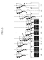
- FIG. 3 is an explanatory diagram explaining a packaging method of one embodiment according to the invention.
- FIG. 4 is a partially enlarged view of the method shown in FIG. 3 ;
- FIG. 5 is a plan view of a closing unit of the packaging machine shown in FIG. 1 ;
- FIG. 6 is a plan view of the closing unit of the packaging machine shown in FIG. 1 , explaining the operation of the closing unit;
- FIG. 7 is an enlarged front view of the closing unit and a temporary sealing unit of the packaging machine shown in FIG. 1 ;
- FIG. 8 is an enlarged front view of an airway securing unit of the packaging machine shown in FIG. 1 , explaining the airway securing unit;
- FIG. 9 is an explanatory diagram explaining the operation of the airway securing unit shown in FIG. 8 ;
- FIG. 10 is also an explanatory diagram explaining the operation of the airway securing unit shown in FIG. 8 ;
- FIG. 11 is an explanatory diagram explaining a conventional deaeration unit
- FIG. 12 is an explanatory diagram explaining the deaeration unit of the packaging machine shown in FIG. 1 ;
- FIG. 13 is an enlarged front view of a shaping press unit of the packaging machine shown in FIG. 1 ;
- FIG. 14 is an enlarged plan view of the shaping press unit shown in FIG. 13 ;
- FIG. 15 is an explanatory diagram explaining a temporary sealing unit of another embodiment.
- FIG. 16 is an explanatory diagram explaining a conventional temporary sealing unit of another embodiment.
- a packaging machine and a packaging method are realized both of which can prevent the packaging bag from being damaged or collapsed during storage in a piled state or transportation by more reliably deaerating even the imperforate bag which can prevent contamination of foreign substances such as insects without any small apertures or any aerating part.
- a packaging machine 1 of an embodiment as shown in FIGS. 1 and 2 fills with an article to be packaged a packaging bag A and eliminates air in the bag A by a deaeration nozzle 3 and heat-seals a mouth a.
- the packaging machine 1 has a closing unit 4 which holds a part of the packaging bag A in a vicinity of the mouth a into which the deaeration nozzle 3 is inserted, from a front and a back of the packaging bag A, thereby closing the packaging bag A.
- the closing unit 4 includes at least a part which holds the deaeration nozzle 3 and is formed of an elastic member 4 c .
- the packaging machine 1 of the embodiment further includes an airway securing unit 10 , a shaping press unit 20 , a temporary sealing unit 40 and a deaeration unit 50 which can carry out a reliable deaeration in a short time.
- the aforesaid units will be described in detail later.
- the packaging machine 1 of the embodiment is a rotary type gas filled packaging machine as shown in FIG. 1 or 2 and fills the packaging bag with an article such as rice, sugar, salt or pet food and then seals the packaging bag.
- a packaging method of the packaging machine 1 includes a bag supply process (1), a zippered bag opening process (2), a bag opening process (3), an article fill process (4), a gas charging process (4) to (6), a shaping, deaeration and temporary sealing process (7), a top seal process (8), a seal cooling process (9) and a product ejecting process.
- the packaging machine 1 includes a machine base 90 on which is provided a stand 92 rotatably supporting a vertical intermittent rotation shaft 93 , as shown in FIG. 1 or 2 .
- a disc-like rotating body 94 is mounted on the intermittent rotation shaft 93 .
- Ten pairs of grips 2 gripping or releasing the packaging bag A are mounted on the rotating body 94 so as to radially protrude at equiangular intervals. The number of grip pairs is equal to the number of steps.
- the paired grips 2 are configured to grip both sides of the bag A near an upper part of the bag A as shown in FIG. 4 respectively.
- a bag placer 96 has a well known structure that packaging bags A laid on a supply stand 97 in a pile are separated one by one from above by a adsorption unit provided with a suction disk ( 100 a , 100 b in FIG. 2 ) to be supplied to the paired grips 2 in a suspended state with a mouth side up.
- Reference numeral 49 designates filling funnels controlled by a drive mechanism (not shown) so that the filling funnels are moved upward and downward.
- Each funnel 49 includes a deaeration nozzle 3 and a gas charging nozzle 6 as shown in FIG. 4 .
- the packaging machine 1 of the embodiment is of the rotary type, the packaging machine of the invention should not be limited to the rotary type.
- a linear travel type packaging machine may be employed, instead.
- the linear travel type packaging machine includes a movable body moved horizontally along an annular passage having, for example, a linear part and semispherical parts on both ends of the linear part.
- a number of paired grips 2 are mounted on the movable body so as to switchable between a standing posture and a horizontal posture.
- Packaging bags A supplied at the bag supply step are supported on respective paired grips 2 , so that the bags A are intermittently stopped at the opening step, the filling step, the top seal step and the like so as to be filled with the article.
- the closing unit 4 is provided for holding a vicinity of the mouth a of the bag A inserted with a deaeration nozzle 3 and a gas charging nozzle 6 , from front and back of the bag A on the occasion of deaeration at the shaping, deaeration and temporary sealing step (7), thereby closing the vicinity of the mouth a of the bag A, as shown in FIG. 4 . Since the vicinity of the mouth a is closed by the closing unit 4 on the occasion of deaeration, more stable and more reliable deaeration is executable as compared with the case where the mouth a of the bag is open.
- the closing unit 4 has a pair of closing bars 4 a and 4 b as shown in FIG. 5 .
- the closing bar 4 a is adapted to be disposed at the front side of the bag A and the closing bar 4 b is adapted to be disposed at the back side of the bag A.
- the closing bars 4 a and 4 b are configured to be moved from the front and back of the bag A to the bag A side and to hold the bag A therebetween thereby to close the vicinity of the mouth a of the bag A.
- Each one of the paired closing bars 4 a and 4 b has a length larger than a width of the bag A in order to close the mouth a of the bag A.
- Each bar 4 a , 4 b includes a portion holding the deaeration nozzle 3 and formed of an elastic member 4 c.
- the bars 4 a and 4 b in the embodiment include middle portions surrounding the deaeration nozzle 3 and the gas charging nozzle 6 respectively when closing the bag A.
- the middle portions of the bars 4 a and 4 b are formed of sponges 4 c , which have both lengthwise sides formed of hard bodies 4 e that are pushed out inward (toward the bag A) by push springs 4 d respectively.
- the sponges 4 c are configured to closely adhere to outer surfaces of the deaeration nozzle 3 and the gas charging nozzle 6 when the bag A is closed, whereby the peripheries of the deaeration nozzle 3 and the gas charging nozzle 6 are also reliably closed, respectively, as shown in FIG. 6 .
- each elastic member 4 c should not be limited to the sponge but may be formed of any material that has a predetermined elasticity and closely adheres to outer surfaces of the nozzles.
- the airway securing unit 10 is provided for securing an airway for the deaeration nozzle 3 in the bag A on the occasion of deaeration. More specifically, when an upper surface of the article filling the bag A is excessively away from the distal end 3 a of the deaeration nozzle 3 , the bags (the front and the back) located between the surface of the article and the distal end 3 a of the nozzle 3 would adhere closely to each other, whereupon it would be difficult or impossible to carry out deaeration, as shown in FIG. 9 .
- the airway securing unit 10 is provided for preventing deaeration from becoming difficult or impossible to carry out.
- the airway securing unit 10 includes suckers 10 a and 10 b provided below the closing unit 4 (paired grips 2 ) for sucking the bag A from the front and the back of the bag A as shown in FIG. 4 or 10 , cylinders 11 a and 11 b for horizontally reciprocating the suckers 10 a and 10 b so that the suckers 10 a and 10 b adhere closely to or depart from the bag A as shown in FIG. 8 , a vacuum pump (not shown) for causing the suckers 10 a and 10 b to adsorb onto the opposed sides of the bag A and to separate the front and back of the bag A from each other thereby to secure an airway, an electromagnetic valve 12 and a regulator 13 for regulating suction pressure.
- suckers 10 a and 10 b provided below the closing unit 4 (paired grips 2 ) for sucking the bag A from the front and the back of the bag A as shown in FIG. 4 or 10
- cylinders 11 a and 11 b for horizontally reciprocating the suckers 10 a
- the suckers 10 a and 10 b adsorbing the front or the front and the back of the bag A are pulled by the cylinders 11 a and 11 b in directions such that the suckers 10 a and 10 b depart from the bag A, whereby the front and back of the bag A are separated from each other.
- the airway securing unit 10 is configured so that an airway for deaeration by the deaeration nozzle 3 can be secured by the above-described operation and deaeration can be executed stably.
- the shaping press unit 20 is provided for shaping the bag A filled with an article into such a shape that the bags can be prevented from being damaged or collapsed during storage in a piled state or transportation.
- the shaping press unit 20 includes a pair of pressing members 22 and 23 to either one of which a vibrator 21 is mounted as shown in FIG. 13 or 14 .
- the pressing members 22 and 23 are allowed to come close to each other and to depart from each other by operation of an actuator (a pneumatic cylinder). Vibration is applied by the vibrator 21 to the bag A filled with the article while the bag A is pressed at the front and rear sides thereof by the pressing members 22 and 23 respectively, so that the article is vertically stretched so as to be shaped into a certain thickness.
- Reference numeral 25 designates a base of a pressing unit 27 mounted via a plurality of vibration-proof rubber pieces 26 on the machine base 90 .
- a pair of right and left side plates 28 stand on the base 25 as shown in FIG. 14 .
- a support member 29 extends between the side plates 28 .
- a flat plate-shaped pressing member 22 is fixed via vibration-proof rubber 30 to the front side of the support member 29 so as to be directed vertically.
- the electrically driven vibrator 21 is fixed to the back side of the pressing member 21 .
- a rotating shaft 32 is horizontally supported on a pair of bearings 31 fixed to the base 25 .
- a swinging member 33 is rotatably supported on the rotating shaft 32 .
- the pressing member 23 is fixed to the swinging member 33 .
- the pressing members 22 and 23 form a front and rear pair and are disposed so that inner surfaces of both pressing members 22 and 23 face each other.
- a rotating shaft 35 is horizontally supported on a pair of bearings 34 fixed to the base 25 .
- the pneumatic cylinder 36 serving as an actuator has a head mounted to the rotating shaft 35 .
- the pneumatic cylinder 36 also has a rod 36 a with a distal end which is rotatably mounted on a back side of the swinging member 33 .
- a push unit 37 is provided for adjunctively pushing the bottom of the bag A upward in the occasion of the temporary heat sealing.
- the bag A filled with the article is placed between the pressing member 22 to which the vibrator 21 is mounted and the pressing member 23 which is allowed to come close to and depart from the pressing member 22 by the actuation of the pneumatic cylinder 36 .
- Vibration by the vibrator 21 is applied to the bag A while the bag A is pressed at the front and rear sides by the pressing members 22 and 23 , so that the article is vertically stretched so as to be shaped into a certain thickness.
- Air in the bag A is eliminated by the deaeration nozzle 3 simultaneously with the shaping by the shaping press unit 20 , whereby the article can be maintained in the shaped state with the predetermined thickness by stretching the same vertically and deaeration can be executed more reliably.
- the temporary sealing unit 40 is provided for maintaining the deaerated state and disposed over the closing unit 4 as shown in FIG. 4 or 8 .
- the temporary sealing unit 40 of the embodiment includes a pair of first and second sealing members 41 and 42 which hold the bag A therebetween and sealing the bag A.
- the first sealing member 41 includes two vertically disposed seal bars 41 a and 41 b one ( 41 a ) of which is comprised of a heating bar and the other ( 41 b ) of which is comprised of an elastic bar (for example, a rubber bar).
- the second sealing member 42 includes a seal bar 42 a disposed opposite the heating bar 41 a of the first sealing member 41 and a seal bar 42 b disposed opposite the elastic bar 41 b of the first sealing member 41 .
- the seal bar 42 a is comprised of an elastic bar and the seal bar 42 b is comprised of a heating bar.
- a temporary sealing unit 70 of another embodiment as shown in FIG. 15 includes a first sealing member 71 having a heating bar (an iron bar) 71 a and a second sealing member 72 having a heating bar (an iron bar) 72 a disposed opposite the heating bar 71 a of the first sealing member 71 .
- the aforementioned temporary sealing unit 40 is used.
- the temporary sealing unit 70 may be used when a bag has no folded portions.
- a conventional temporary sealing unit 80 as shown in FIG. 16 includes a first sealing member 81 having a heating bar (an iron bar) 81 a and a second sealing member 82 having an elastic bar (a rubber bar) 82 a disposed opposite the heating bar 81 a of the first sealing member 81 .
- the temporary sealing unit 40 includes the first sealing member 41 further including two vertically disposed seal bars 41 a and 41 b one ( 41 a ) of which is comprised of the heating bar and the other ( 41 b ) of which is comprised of the elastic bar (for example, a rubber bar).
- the temporary sealing unit 40 also includes the second sealing member 42 further including the seal bar 42 a disposed opposite the heating bar 41 a of the first sealing member 41 and comprised of the elastic bar and the seal bar 42 b disposed opposite the elastic bar 42 b of the first sealing member 41 and comprised of the heating bar. Accordingly, the part m is reliably held between the heating bar and the elastic bar, and the gusset bag A is sealed at the front and back thereof by the heating bar and the elastic bar. Consequently, no folded portions O and P are provided at the side of the elastic bar (the rubber bar) which is not sealed, and thus, even the Gusset bag A can reliably be sealed.
- the first sealing member 41 and the first closing bar 4 a are fixed to the first movable member 7 , which is horizontally reciprocable by a drive unit (not shown) thereby to contact with and depart from the bag A, whereby the first movable member 7 is configured to contact with and depart from the bag A gripped by the paired grips 2 .
- the second sealing member 42 and the second closing bar 4 b are fixed to the second movable member 8 , which is also horizontally reciprocable by a drive unit (not shown) thereby to contact and depart from the bag A, whereby the second movable member 8 is configured to contact with and depart from the front of the bag A gripped by the paired grips 2 .
- a deaeration unit 50 includes a high-pressure vacuum portion 51 and a low-pressure vacuum portion 52 as shown in FIG. 12 .
- the high-pressure or low-pressure portion 51 or 52 is configured to be capable of sucking air remaining in the bag A via filters 53 and 54 by the deaeration nozzle 3 .
- the high-pressure portion 51 includes a vacuum pump 55 , a first electromagnetic valve (SV) 56 , pressure instrumentation 67 and a vacuum controller 58 .
- the low-pressure vacuum portion 52 includes an electronic vacuum regulator 59 and a second electromagnetic valve (SV) 60 .
- a rapid deaeration is carried out by the high-pressure vacuum portion at an initial stage of deaeration and thereafter, the high-pressure vacuum is switched to the low-pressure vacuum.
- the packaging machine is controlled so that a reliable deaeration can be carried out in a short period of time.
- a suitable vacuum pressure different from one bag to another is settable on a touch panel (not shown) with the result that the vacuum pressure is adjustable and a deaeration progress can be adjusted and an ideal deaerated state can be provided in the storage of bags piled one upon another.
- a conventional deaeration unit 61 includes a vacuum pump 62 , an electromagnetic valve (SV) 63 , pressure instrumentation 64 , a vacuum controller 65 , a first filter 66 , a second filter 67 and a deaeration nozzle 3 .
- Low-pressure vacuum control is unstable and the deaeration unit 61 lacks reproducibility, with the result that a reliable deaeration cannot be carried out.
- the packaging method by the packaging machine 1 includes a filling step of filling with an article to be packaged a packaging bag supported in a suspended manner by paired grips 2 with the mouth a thereof on the top, a deaeration step of eliminating air in the packaging bag A by the deaeration nozzle 3 and a sealing step of heat-sealing the mouth a.
- the deaeration step is executed in a condition where a vicinity of the mouth a through which the deaeration nozzle 3 is inserted is held from the front and the back of the packaging bag A thereby to be closed, whereby the bag is deaerated.
- the packaging method of the invention by the packaging machine 1 has ten processes including a bag supply process (1), a zippered bag opening process (2), a bag opening process (3), an article fill process (4), a gas charging process (4) to (6), a shaping, deaeration and temporary sealing process (7), a top seal process (8), a seal cooling process (9) and a product ejecting process. Since the shaping, deaeration and temporary sealing process (7) is characteristic, this process (7) will be described in detail. Furthermore, the configuration of the packaging machine 1 has been described above and detailed description thereof will be eliminated.
- the packaging bag A is held by the paired grips 2 in the bag supply process (1) as shown in FIG. 3 .
- the zippered bag opening process (2) and the bag opening process (3) the bag A is suctioned from the front and the back thereof by a suction unit and the mouth a is closed, and thereafter, the filling funnels 49 are moved downward and distal ends of the deaeration nozzle 3 and the gas displacement nozzle 6 are inserted into the bag A.
- the bag A supported by the paired grips 2 is filled with a predetermined amount of article.
- the gas charging process (4) to (6) the bag A is filled with a gas for preservation of the article.
- the deaeration nozzle 3 is moved upward in the bag A so as to be located over the upper surface of the article.
- the vicinity of the mouth a in the bag A inserted with the deaeration nozzle 3 and the gas fill nozzle 6 is held from the front and the back thereof by the closing unit 4 thereby to be closed.
- the first closing bar 4 a is brought into contact with the bag A by horizontally moving the first moving body 7 from the front side of the bag A
- the second closing bar 4 b is brought into contact with the bag A by horizontally moving the second moving body 8 from the back side of the bag A, whereby the bag A is held between the first and second closing bars 4 a and 4 b from the front and the back thereof thereby to be closed.
- the middle portions of the closing bars 4 a and 4 b constituting the peripheries of the deaeration nozzle 3 and the gas charging nozzle 6 are formed of the elastic members (sponges) 4 c , respectively, the sponges 4 c closely adhere to outer surfaces of the deaeration nozzle 3 and the gas charging nozzle 6 with the result that the peripheries of the aeration nozzle 3 and the gas charging nozzle 6 are reliably be closed. Consequently, since the vicinity of the mouth a is closed, more stable and more reliable deaeration is executable as compared with the case where the mouth a of the bag is open.
- the surface and back sides of the bag A are pulled by the cylinders 11 a and 11 b in such directions that the suckers 10 a and 10 b depart from the bag A, while the suckers 10 a and 10 b adsorb the front and back sides of the bag A. Consequently, the surface and back sides of the bag A are separated from each other with the result that an airway for deaeration by the deaeration nozzle 3 can reliably be secured.
- Deaeration and shaping are simultaneously carried out in the above-described state. More specifically, the bag A filled with the article is placed between pressing members 22 and 23 . Vibration is applied to the bag A by the vibrator 21 while the bag A is pressed from the surface and back sides thereof by the pressing members 22 and 23 , whereby the article is vertically stretched to be shaped into the predetermined thickness.
- Air in the bag A is eliminated by the deaeration nozzle 3 simultaneously with the shaping by the shaping press unit 20 , whereby the article can be maintained in the shaped state with the predetermined thickness by stretching the same vertically and deaeration can be executed more reliably. Furthermore, a rapid deaeration is carried out by the high-pressure vacuum portion at an initial stage of deaeration and thereafter, the high-pressure vacuum is switched to the low-pressure vacuum. Consequently, an accurate deaeration is carried out in a short period of time.
- the deaeration nozzle 3 and the gas charging nozzle 6 are moved upward thereby to depart from the mouth a of the bag A and the mouth a is immediately sealed by the temporary sealing unit 40 . More specifically, the first sealing body 41 is brought into contact with the bag A by horizontally moving the first moving body 7 from the front side of the bag A, and the second sealing body 41 is brought into contact with the bag A by horizontally moving the second moving body 8 from the back side of the bag A, whereby the temporary sealing is carried out.
- one ( 41 a ) of the two vertically disposed seal bars 41 a and 41 b of the first sealing body 41 is comprised of the heating bar and the other ( 41 b ) is comprised of the elastic bar (rubber bar, for example).
- the seal bar 42 a of the second sealing body 42 disposed opposite the heating bar 41 a of the first seal body 41 is comprised of the elastic bar and the seal bar 42 b of the second sealing body 42 is comprised of the heating bar. Consequently, the bag A is reliably sealed.
- the vicinity of the mouth a of the packaging bag A is reliably closed by the closing unit 4 .
- the airway for deaeration is reliably secured by the airway securing unit 10 .
- Shaping is carried out by the shaping press unit 20 with deaeration being executed.
- High-pressure vacuum is employed at the initial stage of deaeration and thereafter, the high-pressure vacuum is switched to low-pressure vacuum, whereupon accurate deaeration is carried out in a short period of time.
- the temporary sealing unit 40 is provided which reliably seals even the Gusset bag.
- the top seal is applied to the bag in the top seal process (7) and the part to which the top seal has been applied is cooled in the cooling process (8). Furthermore, the bag A is ejected onto the conveyor in the product ejection process (9), whereby packaging by the packaging machine 1 of the invention is completed.
- the temporary sealing unit 40 is dedicated to temporary sealing in the above-described packaging machine 1 or packaging method. In the top seal process executed after the temporary sealing, the top seal is applied to the bag using another top seal unit.
- the packaging machine and the packaging method of the invention include the configuration and use of the temporary sealing unit 40 as the top sealing unit.
- the temporary sealing unit 40 is used to temporarily seal the Gusset bag in the above-described packaging machine and the packaging method
- the packaging machine and the packaging method of the invention include use of the temporary sealing unit 40 in temporary sealing or top sealing of bags other than the Gusset bag.
Landscapes
- Engineering & Computer Science (AREA)
- Mechanical Engineering (AREA)
- Chemical & Material Sciences (AREA)
- Dispersion Chemistry (AREA)
- Vacuum Packaging (AREA)
- Package Closures (AREA)
Applications Claiming Priority (1)
| Application Number | Priority Date | Filing Date | Title |
|---|---|---|---|
| PCT/JP2012/057855 WO2013145113A1 (ja) | 2012-03-27 | 2012-03-27 | 包装機およびその包装方法 |
Publications (2)
| Publication Number | Publication Date |
|---|---|
| US20140033649A1 US20140033649A1 (en) | 2014-02-06 |
| US9957069B2 true US9957069B2 (en) | 2018-05-01 |
Family
ID=49258482
Family Applications (1)
| Application Number | Title | Priority Date | Filing Date |
|---|---|---|---|
| US14/003,877 Active 2034-09-08 US9957069B2 (en) | 2012-03-27 | 2012-03-27 | Packaging machine and packaging method |
Country Status (7)
| Country | Link |
|---|---|
| US (1) | US9957069B2 (pl) |
| EP (1) | EP2832650B1 (pl) |
| JP (1) | JP6093922B2 (pl) |
| KR (1) | KR101906960B1 (pl) |
| CA (1) | CA2828282C (pl) |
| PL (1) | PL2832650T3 (pl) |
| WO (1) | WO2013145113A1 (pl) |
Cited By (3)
| Publication number | Priority date | Publication date | Assignee | Title |
|---|---|---|---|---|
| US20170036791A1 (en) * | 2015-08-04 | 2017-02-09 | Pinnacle Foods Group Llc | Shelf-stable pouch for fresh-packed fruits or vegetables |
| US11420779B2 (en) * | 2017-04-05 | 2022-08-23 | General Packer Co., Ltd. | Packaging method used in bag-feeding and packaging apparatus, and the bag-feeding and packaging apparatus |
| US20230066934A1 (en) * | 2020-04-23 | 2023-03-02 | Nippon Paper Industries Co., Ltd. | Method for packaging cellulosic polymer, method for transporting the same, and cellulosic polymer package |
Families Citing this family (23)
| Publication number | Priority date | Publication date | Assignee | Title |
|---|---|---|---|---|
| GB201315499D0 (en) * | 2013-08-30 | 2013-10-16 | British American Tobacco Co | A vending machine |
| ES2678995T3 (es) * | 2015-03-13 | 2018-08-21 | Ecolean Ab | Equipo y método para llenar un envase del tipo de bolsa |
| JP6507349B2 (ja) * | 2015-04-06 | 2019-05-08 | ゼネラルパッカー株式会社 | ガス充填包装機およびガス充填包装機における不活性ガス充填方法 |
| KR101960444B1 (ko) | 2016-04-20 | 2019-03-20 | 박화춘 | 배기부를 갖는 로터리형 자동포장장치 |
| CN108100349B (zh) * | 2016-11-25 | 2024-02-06 | 南京一擎机械制造有限公司 | 封口架装置 |
| CN107336870B (zh) * | 2017-08-11 | 2023-04-18 | 长春理工大学 | 旋转双工位钢球自动包装装置及方法 |
| CN109018554B (zh) * | 2018-07-01 | 2020-05-19 | 高邮亚普塑业有限公司 | 一种医用tpe粒料的制备系统 |
| CN108974464B (zh) * | 2018-07-04 | 2024-07-02 | 吴付利 | 一种用于产品装袋及热封的装置 |
| CN109775048A (zh) * | 2019-03-18 | 2019-05-21 | 浙江古川机械有限公司 | 给袋式包装机的加料方法及装置 |
| CN110406722A (zh) * | 2019-08-30 | 2019-11-05 | 无锡满意包装机械有限公司 | 全自动粉料热合抽气装置 |
| KR102453752B1 (ko) * | 2019-09-23 | 2022-10-14 | 이기철 | 외부공기 유입방지구가 형성되는 회전식 식품 진공포장기 |
| CN111792085A (zh) * | 2020-05-19 | 2020-10-20 | 芜湖飞元智能装备有限公司 | 一种用于食品的真空包装装置及其包装方法 |
| CN111717472A (zh) * | 2020-06-24 | 2020-09-29 | 萍乡市华顺环保化工填料有限公司 | 一种全自动真空包装机 |
| CN111806796B (zh) * | 2020-06-30 | 2021-08-31 | 长沙师范学院 | 一种用于包装的包装袋封口装置 |
| CN112896638B (zh) * | 2021-01-20 | 2022-06-14 | 江西东坚农业发展有限公司 | 一种称重式大米装袋设备 |
| KR102627803B1 (ko) * | 2021-04-06 | 2024-01-19 | 방의규 | 백 자동 포장 방법 |
| CN113212875B (zh) * | 2021-06-23 | 2022-06-28 | 厚德食品股份有限公司 | 一种自动给袋式蛋制品包装设备 |
| CN113353350B (zh) * | 2021-07-13 | 2025-03-25 | 朗锐包装技术(沧州)有限公司 | 一种跟随下料机构 |
| CN113734529A (zh) * | 2021-09-07 | 2021-12-03 | 芜湖万向新元智能科技有限公司 | 一种料袋自动封口机 |
| CN113942691B (zh) * | 2021-11-12 | 2022-12-13 | 漳州青牛科技有限公司 | 一种两面真空包装的装置 |
| CN117125302A (zh) * | 2023-09-14 | 2023-11-28 | 哈尔滨创博智能装备有限公司 | 一种套袋真空封口机 |
| CN117566177A (zh) * | 2024-01-17 | 2024-02-20 | 朗锐包装技术(沧州)有限公司 | 一种跟随式充氮下料集成机构 |
| CN117944968B (zh) * | 2024-03-26 | 2024-06-21 | 四川远方云天食品科技有限公司 | 一种火锅底料包装封口设备 |
Citations (12)
| Publication number | Priority date | Publication date | Assignee | Title |
|---|---|---|---|---|
| US3182432A (en) * | 1962-05-21 | 1965-05-11 | Bartelt Engineering Co Inc | Machine for packaging products in a controlled atmosphere |
| US4027456A (en) * | 1976-01-19 | 1977-06-07 | Fmc Corporation | Air-free pouch packaging method |
| JPS6299503U (pl) | 1985-12-11 | 1987-06-25 | ||
| JPH0834412A (ja) | 1994-07-20 | 1996-02-06 | Shinku Kagaku Kenkyusho | 急速減圧装置 |
| JPH10114307A (ja) | 1996-10-08 | 1998-05-06 | Kobayashi Kogu Seisakusho:Kk | 自動穀類袋詰装置 |
| JPH10181713A (ja) | 1996-12-24 | 1998-07-07 | Shinsei:Kk | 間歇回転形充填包装機における包装袋の真空方法とその真空装置 |
| JPH10230913A (ja) | 1997-02-14 | 1998-09-02 | Windmoeller & Hoelscher | 片側の開いた袋の充填及び閉鎖のための方法及び装置 |
| EP1378450A1 (en) | 2002-07-02 | 2004-01-07 | Interprise - Brussels S.A. | Method and apparatus for vacuum bagging a good |
| US20050276521A1 (en) * | 2004-05-27 | 2005-12-15 | Price Charles E | Packaging for particulate and granular materials |
| US20090223172A1 (en) * | 2005-09-07 | 2009-09-10 | General Packer Co., Ltd. | Method for Placing Inert Gas in Gas-Filling Packaging Machine |
| EP2103520A1 (de) | 2008-03-17 | 2009-09-23 | Haver & Boecker oHG | Behandlungseinrichtung und Verfahren zum Behandeln eines mit einem Schüttgut gefüllten offenen Sacks |
| JP2010126244A (ja) | 2008-12-01 | 2010-06-10 | General Packer Co Ltd | 包装方法 |
Family Cites Families (1)
| Publication number | Priority date | Publication date | Assignee | Title |
|---|---|---|---|---|
| JP4572381B2 (ja) * | 2004-07-29 | 2010-11-04 | ゼネラルパッカー株式会社 | 塊状被包装物の包装方法 |
-
2012
- 2012-03-27 PL PL12872823T patent/PL2832650T3/pl unknown
- 2012-03-27 EP EP12872823.5A patent/EP2832650B1/en active Active
- 2012-03-27 JP JP2014507083A patent/JP6093922B2/ja active Active
- 2012-03-27 CA CA2828282A patent/CA2828282C/en active Active
- 2012-03-27 KR KR1020147011207A patent/KR101906960B1/ko active Active
- 2012-03-27 WO PCT/JP2012/057855 patent/WO2013145113A1/ja not_active Ceased
- 2012-03-27 US US14/003,877 patent/US9957069B2/en active Active
Patent Citations (12)
| Publication number | Priority date | Publication date | Assignee | Title |
|---|---|---|---|---|
| US3182432A (en) * | 1962-05-21 | 1965-05-11 | Bartelt Engineering Co Inc | Machine for packaging products in a controlled atmosphere |
| US4027456A (en) * | 1976-01-19 | 1977-06-07 | Fmc Corporation | Air-free pouch packaging method |
| JPS6299503U (pl) | 1985-12-11 | 1987-06-25 | ||
| JPH0834412A (ja) | 1994-07-20 | 1996-02-06 | Shinku Kagaku Kenkyusho | 急速減圧装置 |
| JPH10114307A (ja) | 1996-10-08 | 1998-05-06 | Kobayashi Kogu Seisakusho:Kk | 自動穀類袋詰装置 |
| JPH10181713A (ja) | 1996-12-24 | 1998-07-07 | Shinsei:Kk | 間歇回転形充填包装機における包装袋の真空方法とその真空装置 |
| JPH10230913A (ja) | 1997-02-14 | 1998-09-02 | Windmoeller & Hoelscher | 片側の開いた袋の充填及び閉鎖のための方法及び装置 |
| EP1378450A1 (en) | 2002-07-02 | 2004-01-07 | Interprise - Brussels S.A. | Method and apparatus for vacuum bagging a good |
| US20050276521A1 (en) * | 2004-05-27 | 2005-12-15 | Price Charles E | Packaging for particulate and granular materials |
| US20090223172A1 (en) * | 2005-09-07 | 2009-09-10 | General Packer Co., Ltd. | Method for Placing Inert Gas in Gas-Filling Packaging Machine |
| EP2103520A1 (de) | 2008-03-17 | 2009-09-23 | Haver & Boecker oHG | Behandlungseinrichtung und Verfahren zum Behandeln eines mit einem Schüttgut gefüllten offenen Sacks |
| JP2010126244A (ja) | 2008-12-01 | 2010-06-10 | General Packer Co Ltd | 包装方法 |
Non-Patent Citations (6)
| Title |
|---|
| Communication Pursuant to Article 94(3) EPC for EP Patent App. No. 12872823.5 dated May 20, 2016. |
| International Search Report and Written Opinion for PCT Patent App. No. PCT/JP2012/057855 dated May 1, 2012. |
| Office Action for Japanese Patent App. No. 2014-507083 dated Nov. 16, 2015. |
| Office Action from Canadian Patent App. No. 2,828,282 (dated Dec. 27, 2017). |
| Search Report on the State of the Art for Polish App. No. P409490 dated Aug. 7, 2015. |
| Supplementary European Search Report for European Patent App. No. 12872823.5 dated Sep. 25, 2015. |
Cited By (4)
| Publication number | Priority date | Publication date | Assignee | Title |
|---|---|---|---|---|
| US20170036791A1 (en) * | 2015-08-04 | 2017-02-09 | Pinnacle Foods Group Llc | Shelf-stable pouch for fresh-packed fruits or vegetables |
| US10974855B2 (en) * | 2015-08-04 | 2021-04-13 | Conagra Foods Rdm, Inc. | Shelf-stable pouch for fresh-packed fruits or vegetables |
| US11420779B2 (en) * | 2017-04-05 | 2022-08-23 | General Packer Co., Ltd. | Packaging method used in bag-feeding and packaging apparatus, and the bag-feeding and packaging apparatus |
| US20230066934A1 (en) * | 2020-04-23 | 2023-03-02 | Nippon Paper Industries Co., Ltd. | Method for packaging cellulosic polymer, method for transporting the same, and cellulosic polymer package |
Also Published As
| Publication number | Publication date |
|---|---|
| EP2832650B1 (en) | 2017-03-22 |
| EP2832650A1 (en) | 2015-02-04 |
| JPWO2013145113A1 (ja) | 2015-08-03 |
| JP6093922B2 (ja) | 2017-03-15 |
| KR20140138106A (ko) | 2014-12-03 |
| CA2828282A1 (en) | 2013-09-27 |
| CA2828282C (en) | 2018-11-20 |
| US20140033649A1 (en) | 2014-02-06 |
| PL2832650T3 (pl) | 2017-09-29 |
| KR101906960B1 (ko) | 2018-10-11 |
| WO2013145113A1 (ja) | 2013-10-03 |
| EP2832650A4 (en) | 2015-10-28 |
Similar Documents
| Publication | Publication Date | Title |
|---|---|---|
| EP2832650B1 (en) | Packaging machine and packaging method | |
| KR102216457B1 (ko) | 포장기 | |
| CN206502056U (zh) | 大红袍棱角数控包装机 | |
| JP5266446B2 (ja) | 包装方法 | |
| KR20210034845A (ko) | 외부공기 유입방지구가 형성되는 회전식 식품 진공포장기 | |
| US10954017B2 (en) | Packaging machine and sealing method in packaging machine | |
| US2840964A (en) | Evacuating and sealing apparatus | |
| JP6713194B2 (ja) | 包装装置 | |
| JP5740581B2 (ja) | 給袋自動包装機 | |
| WO2018020784A1 (ja) | ロータリー式包装機 | |
| JP2008007139A (ja) | 圧縮充填包装方法 | |
| US20210300610A1 (en) | Packaging machine with bottom-supporting device | |
| JP3945865B2 (ja) | 包装袋の整形装置 | |
| JP3751603B2 (ja) | 飲料用被抽出材料の抽出バッグへの包装方法 | |
| JP3742052B2 (ja) | トレーを用いる包装方法 | |
| JP2007091306A (ja) | ロータリー式縦型充填機及び2ローター式縦型真空包装装置 | |
| JP6103665B1 (ja) | ガス置換包装機 | |
| JP6085836B2 (ja) | 包装機 | |
| JP6491021B2 (ja) | 袋詰め品押え装置及び方法 | |
| CN217171136U (zh) | 一种软包装袋热封机上袋机构 | |
| JP4639369B2 (ja) | 被包装物の圧縮充填方法 | |
| KR20190011676A (ko) | 주머니체 반송 처리 방법 및 주머니체 반송 처리 장치 | |
| JP2025184383A (ja) | ガス置換包装機 | |
| JPH0811807A (ja) | 自動袋詰め装置並びに泡除去装置 | |
| JPH0232926A (ja) | 包装方法 |
Legal Events
| Date | Code | Title | Description |
|---|---|---|---|
| AS | Assignment |
Owner name: GENERAL PACKER CO., LTD., JAPAN Free format text: ASSIGNMENT OF ASSIGNORS INTEREST;ASSIGNORS:ISHIKAWA, SHINJI;OZEKI, SHINYA;REEL/FRAME:031163/0677 Effective date: 20130827 |
|
| STCF | Information on status: patent grant |
Free format text: PATENTED CASE |
|
| MAFP | Maintenance fee payment |
Free format text: PAYMENT OF MAINTENANCE FEE, 4TH YR, SMALL ENTITY (ORIGINAL EVENT CODE: M2551); ENTITY STATUS OF PATENT OWNER: SMALL ENTITY Year of fee payment: 4 |
|
| MAFP | Maintenance fee payment |
Free format text: PAYMENT OF MAINTENANCE FEE, 8TH YR, SMALL ENTITY (ORIGINAL EVENT CODE: M2552); ENTITY STATUS OF PATENT OWNER: SMALL ENTITY Year of fee payment: 8 |