US99581A - mcelevey - Google Patents
mcelevey Download PDFInfo
- Publication number
- US99581A US99581A US99581DA US99581A US 99581 A US99581 A US 99581A US 99581D A US99581D A US 99581DA US 99581 A US99581 A US 99581A
- Authority
- US
- United States
- Prior art keywords
- grate
- recess
- plate
- open
- fire
- Prior art date
- Legal status (The legal status is an assumption and is not a legal conclusion. Google has not performed a legal analysis and makes no representation as to the accuracy of the status listed.)
- Expired - Lifetime
Links
Images
Classifications
-
- F—MECHANICAL ENGINEERING; LIGHTING; HEATING; WEAPONS; BLASTING
- F24—HEATING; RANGES; VENTILATING
- F24B—DOMESTIC STOVES OR RANGES FOR SOLID FUELS; IMPLEMENTS FOR USE IN CONNECTION WITH STOVES OR RANGES
- F24B1/00—Stoves or ranges
- F24B1/18—Stoves with open fires, e.g. fireplaces
- F24B1/191—Component parts; Accessories
- F24B1/193—Grates; Irons
Definitions
- pan-n1 can.
- Figure 2 is -a detail front view of the detachable open back.
- My invention has for its object to improve the construction ofgrates for fire-places and stoves, so that a draught may be introduced into the rear side of the fire, and introduced in such a way that it may be controlled as may be desired;
- 'My improvement may be connected with a fireplace or open stove, as may be desired,'but I will describe it as applied to a fire-place.
- A is a fire-place, the back part of which, in the rear of the grate, is recessed, as shown in fig.- 1, said recess B being extended upward, above the grate, as shown in the figure.
- 0 represents the ordinary basket-grate, the forward part of which is hung upon lugs, secured to the jambs, in the ordinary manner.
- the rear edge of the bottom part 'of the grate O rests upon lugs, formed upon the lower edge of the grate-back D, as shown in figs. 1 and 2.
- the grateback I) is "inade open or slotted, in a manner similar to an ordinary grate-bottom, and may he made straight or curved, as may be desired.
- the plate E is a thin metal or tile plate, extending from the upper edge of the grate-back D to the top of the recess B, as shown in fig. 1.
- the plate E may be made solid with the grate-back D, or in a separate piece, as may be desired or convenient, and is designed'to conduct the heat to the air in the upper part of the recess-B, and heat the said air before it is introduced into the fire to support combustion.
- the plate F is a metal plate, which extends up through the recess B, in the rear of the grate-back D, dividing said recess into two compartments.
- the plate F is attached or pivoted, at or near its lower edge, to lugs, pins, or supports,,attached to the sides of the recess B, in such positions that the lower part of said plate may rest against the lower part of the grate-back, so
- the upper part of the plate F may be left free, and its movementbe limited by the back of the recess B, and by the grate-back D, or its rearward movement may be limited by lugs or pins, attached to the sides of said recess.
- a rod, G To the upper part of the plate F, near one end, is attached one end of a rod, G, the. other end of which passes out to, andprqjects beyond the upper edge of the front of the grate C.
- the plate F may be adjusted to regulate the passage of air to the grate-back, or, by drawing the plate F close up against the said grate-back, entirely exclude the air.
- the rod G may be provided with a hook or catch to catch upon the upper bar of the grate-front, and thus secure the plate F in place, when adjusted. This catch may, ifdesired, be made adjustable, so that the plateF-may be secured in any desired position.
- the thin metal or tile plate E whether made solid with, or separate from the-open grate-back D, in combination with the said open grate-back D, and with the upwardly-extended recess B, substantially as herein shown and described, and for the purpose set forth.
- the metal plate F in combination with the recess B, open grate-back D, and plate E, substantially as herein shown and described, and finthepurpose set forth, whether said plate F be pivoted or stationary. 5.
- the combination of the rod G, with the pivoted plateF, open grate-back D, and grate O substantiah
Landscapes
- Engineering & Computer Science (AREA)
- Chemical & Material Sciences (AREA)
- Combustion & Propulsion (AREA)
- Mechanical Engineering (AREA)
- General Engineering & Computer Science (AREA)
- Baking, Grill, Roasting (AREA)
Description
G. H.McELEVEY.
Grate.
No. 99,581. Patented Feb. 8, 1870.
JWM
N.PETER9, PMOTO-UTHOGRAPHEI. WASHINGTON, Dv C.
pan-n1 can.
G. H. MCELEVEY, OF NEWCASTLE, PENNSYLVANIA.
Letters Patent No. 99,581, dated February 8, 1870.
Ihe Schedule referred to in these Letters Patent and making part of the same To all whom it may concern Beit known that I, G. H. MoEnnvEY, ofNewcastle, in the county of Lawrence, and State of Penn sylvania, have invented a. newand improved Grate; and I do hereby declare that the'following is a full,
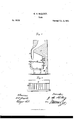
clear, and exact description thereof, which will enable others skilled in the art to make and use the same, reference being had to the accompanying drawings, forming part of this specification, in which- Figure 1.is a vertical longitudinal section of my improved grate, and-the fire-place with which it is connccted.
Figure 2 is -a detail front view of the detachable open back.
Similar letters of reference indicate corresponding parts.
My invention has for its object to improve the construction ofgrates for fire-places and stoves, so that a draught may be introduced into the rear side of the fire, and introduced in such a way that it may be controlled as may be desired; and
- It consists in the construction of various parts of the apparatus, as hereinafter more fully described.
'My improvement may be connected with a fireplace or open stove, as may be desired,'but I will describe it as applied to a fire-place.
A is a fire-place, the back part of which, in the rear of the grate, is recessed, as shown in fig.- 1, said recess B being extended upward, above the grate, as shown in the figure.
0 represents the ordinary basket-grate, the forward part of which is hung upon lugs, secured to the jambs, in the ordinary manner.
The rear edge of the bottom part 'of the grate O rests upon lugs, formed upon the lower edge of the grate-back D, as shown in figs. 1 and 2. The grateback I) is "inade open or slotted, in a manner similar to an ordinary grate-bottom, and may he made straight or curved, as may be desired.
E is a thin metal or tile plate, extending from the upper edge of the grate-back D to the top of the recess B, as shown in fig. 1. The plate E may be made solid with the grate-back D, or in a separate piece, as may be desired or convenient, and is designed'to conduct the heat to the air in the upper part of the recess-B, and heat the said air before it is introduced into the fire to support combustion.
F is a metal plate, which extends up through the recess B, in the rear of the grate-back D, dividing said recess into two compartments. The plate F is attached or pivoted, at or near its lower edge, to lugs, pins, or supports,,attached to the sides of the recess B, in such positions that the lower part of said plate may rest against the lower part of the grate-back, so
that the air will pass up through the rear compartment 'of the recess B, be heated in the upper part of said recess, and pass down to the firethrough its forward compartment, and through the open grate-back, acting as a hot blast to the fire.
The upper part of the plate F may be left free, and its movementbe limited by the back of the recess B, and by the grate-back D, or its rearward movement may be limited by lugs or pins, attached to the sides of said recess.
To the upper part of the plate F, near one end, is attached one end of a rod, G, the. other end of which passes out to, andprqjects beyond the upper edge of the front of the grate C.
By this construction, by means of the rod G, the
plate F may be adjusted to regulate the passage of air to the grate-back, or, by drawing the plate F close up against the said grate-back, entirely exclude the air. The rod G may be provided with a hook or catch to catch upon the upper bar of the grate-front, and thus secure the plate F in place, when adjusted. This catch may, ifdesired, be made adjustable, so that the plateF-may be secured in any desired position.
Havingthns described my invention,
1 claim as new, and desire to secure by Letters Patentl. The separate open grate-back D, in combination with an ordinary grate, and with the recess-B, formed in the rear of said grate, substantially as herein shown and described, and for the purpose set forth.
2. The recess B, formed in the rear of the grate, and extending above the said grate, in combination with the open grate-back D, substantially as herein shown and described, and for the purpose set forth.
3. The thin metal or tile plate E, whether made solid with, or separate from the-open grate-back D, in combination with the said open grate-back D, and with the upwardly-extended recess B, substantially as herein shown and described, and for the purpose set forth. 4. The metal plate F, in combination with the recess B, open grate-back D, and plate E, substantially as herein shown and described, and finthepurpose set forth, whether said plate F be pivoted or stationary. 5. The combination of the rod G, with the pivoted plateF, open grate-back D, and grate O, substantiah,
ly as herein shown and described, andfor the purpose set forth.
The above specification of my invention signed by me, this 16th day of November, 1869.
G. H. MOELEVEY.
WVitnesses J. N. PHILLIPS, E. F. TAIT.
Publications (1)
| Publication Number | Publication Date |
|---|---|
| US99581A true US99581A (en) | 1870-02-08 |
Family
ID=2169040
Family Applications (1)
| Application Number | Title | Priority Date | Filing Date |
|---|---|---|---|
| US99581D Expired - Lifetime US99581A (en) | mcelevey |
Country Status (1)
| Country | Link |
|---|---|
| US (1) | US99581A (en) |
Cited By (1)
| Publication number | Priority date | Publication date | Assignee | Title |
|---|---|---|---|---|
| US4058108A (en) * | 1975-09-08 | 1977-11-15 | Radiant Grate, Inc. | Grate |
-
0
- US US99581D patent/US99581A/en not_active Expired - Lifetime
Cited By (1)
| Publication number | Priority date | Publication date | Assignee | Title |
|---|---|---|---|---|
| US4058108A (en) * | 1975-09-08 | 1977-11-15 | Radiant Grate, Inc. | Grate |
Similar Documents
| Publication | Publication Date | Title |
|---|---|---|
| US90331A (en) | corse | |
| US82574A (en) | Williams | |
| US95972A (en) | Improvement in fire-place stoves | |
| US124325A (en) | Improvement in the grates and doors of open-grate or parlor stoves | |
| US140621A (en) | Improvement in fire-places | |
| US90719A (en) | Margaret armstrong | |
| US92049A (en) | Fire-place grate | |
| US171612A (en) | Improvement in fire-place heaters | |
| US101341A (en) | William e | |
| US138093A (en) | Improvement in cooking-stoves | |
| US83877A (en) | Benjamin nott | |
| US61790A (en) | Adams | |
| US95811A (en) | Julius gustav kluge | |
| US605713A (en) | Fireplace-heater | |
| US80476A (en) | William hailes | |
| US83798A (en) | Improvement in cooking-stoves | |
| US91992A (en) | Joseph b | |
| US89180A (en) | Base-burning stove | |
| US87688A (en) | Souri | |
| US142933A (en) | Improvement in reservoir cooking-stoves | |
| US89713A (en) | John vattee | |
| US81053A (en) | woodcock | |
| US107394A (en) | James h | |
| US97902A (en) | gj bbs | |
| US117696A (en) | Improvement in base-burning stoves |