US9975430B2 - Pointer instrument having a double pointer and an eccentrically arranged fastening column - Google Patents
Pointer instrument having a double pointer and an eccentrically arranged fastening column Download PDFInfo
- Publication number
- US9975430B2 US9975430B2 US15/028,673 US201415028673A US9975430B2 US 9975430 B2 US9975430 B2 US 9975430B2 US 201415028673 A US201415028673 A US 201415028673A US 9975430 B2 US9975430 B2 US 9975430B2
- Authority
- US
- United States
- Prior art keywords
- pointer
- ring segment
- instrument
- light
- pointer instrument
- Prior art date
- Legal status (The legal status is an assumption and is not a legal conclusion. Google has not performed a legal analysis and makes no representation as to the accuracy of the status listed.)
- Active, expires
Links
Images


Classifications
-
- B60K37/02—
-
- G—PHYSICS
- G01—MEASURING; TESTING
- G01D—MEASURING NOT SPECIALLY ADAPTED FOR A SPECIFIC VARIABLE; ARRANGEMENTS FOR MEASURING TWO OR MORE VARIABLES NOT COVERED IN A SINGLE OTHER SUBCLASS; TARIFF METERING APPARATUS; MEASURING OR TESTING NOT OTHERWISE PROVIDED FOR
- G01D13/00—Component parts of indicators for measuring arrangements not specially adapted for a specific variable
- G01D13/22—Pointers, e.g. settable pointer
-
- B—PERFORMING OPERATIONS; TRANSPORTING
- B60—VEHICLES IN GENERAL
- B60K—ARRANGEMENT OR MOUNTING OF PROPULSION UNITS OR OF TRANSMISSIONS IN VEHICLES; ARRANGEMENT OR MOUNTING OF PLURAL DIVERSE PRIME-MOVERS IN VEHICLES; AUXILIARY DRIVES FOR VEHICLES; INSTRUMENTATION OR DASHBOARDS FOR VEHICLES; ARRANGEMENTS IN CONNECTION WITH COOLING, AIR INTAKE, GAS EXHAUST OR FUEL SUPPLY OF PROPULSION UNITS IN VEHICLES
- B60K35/00—Instruments specially adapted for vehicles; Arrangement of instruments in or on vehicles
- B60K35/20—Output arrangements, i.e. from vehicle to user, associated with vehicle functions or specially adapted therefor
-
- B—PERFORMING OPERATIONS; TRANSPORTING
- B60—VEHICLES IN GENERAL
- B60K—ARRANGEMENT OR MOUNTING OF PROPULSION UNITS OR OF TRANSMISSIONS IN VEHICLES; ARRANGEMENT OR MOUNTING OF PLURAL DIVERSE PRIME-MOVERS IN VEHICLES; AUXILIARY DRIVES FOR VEHICLES; INSTRUMENTATION OR DASHBOARDS FOR VEHICLES; ARRANGEMENTS IN CONNECTION WITH COOLING, AIR INTAKE, GAS EXHAUST OR FUEL SUPPLY OF PROPULSION UNITS IN VEHICLES
- B60K35/00—Instruments specially adapted for vehicles; Arrangement of instruments in or on vehicles
- B60K35/60—Instruments characterised by their location or relative disposition in or on vehicles
-
- B60K2350/403—
-
- B60K2350/408—
-
- B—PERFORMING OPERATIONS; TRANSPORTING
- B60—VEHICLES IN GENERAL
- B60K—ARRANGEMENT OR MOUNTING OF PROPULSION UNITS OR OF TRANSMISSIONS IN VEHICLES; ARRANGEMENT OR MOUNTING OF PLURAL DIVERSE PRIME-MOVERS IN VEHICLES; AUXILIARY DRIVES FOR VEHICLES; INSTRUMENTATION OR DASHBOARDS FOR VEHICLES; ARRANGEMENTS IN CONNECTION WITH COOLING, AIR INTAKE, GAS EXHAUST OR FUEL SUPPLY OF PROPULSION UNITS IN VEHICLES
- B60K2360/00—Indexing scheme associated with groups B60K35/00 or B60K37/00 relating to details of instruments or dashboards
- B60K2360/151—Instrument output devices for configurable output
- B60K2360/1515—Reconfigurable dials
-
- B—PERFORMING OPERATIONS; TRANSPORTING
- B60—VEHICLES IN GENERAL
- B60K—ARRANGEMENT OR MOUNTING OF PROPULSION UNITS OR OF TRANSMISSIONS IN VEHICLES; ARRANGEMENT OR MOUNTING OF PLURAL DIVERSE PRIME-MOVERS IN VEHICLES; AUXILIARY DRIVES FOR VEHICLES; INSTRUMENTATION OR DASHBOARDS FOR VEHICLES; ARRANGEMENTS IN CONNECTION WITH COOLING, AIR INTAKE, GAS EXHAUST OR FUEL SUPPLY OF PROPULSION UNITS IN VEHICLES
- B60K2360/00—Indexing scheme associated with groups B60K35/00 or B60K37/00 relating to details of instruments or dashboards
- B60K2360/60—Structural details of dashboards or instruments
- B60K2360/68—Features of instruments
- B60K2360/698—Pointers of combined instruments
Definitions
- the invention relates to a pointer instrument, in particular in a motor vehicle, with a central indicating unit arranged on a fastening column.
- the fastening column is arranged outside of the center of the indicating unit, with an indicating surface concentrically surrounding the indicating unit, and with a centrally supported first pointer for visibly pivoting over the indicating surface.
- the indicating unit is arranged in front of the pointer from the viewpoint of the observer.
- the central indicating unit is a display for indicating a very wide variety of information, combined with an indicating surface surrounding the display.
- the annular indicating surface has a scale across which the pointer sweeps.
- the centrally supported pointer can be pivoted only through an angle range of approximately 300°. It is thus not possible for the entire indicating surface to be utilized for pointer-based presentation of information.
- An aspect of the invention is to make available a pointer instrument in which the entire indicating surface can be utilized for pointer-based presentation of information.
- a second pointer which has a recess for surrounding the fastening column, is arranged concentrically with respect to the first pointer.
- the indicating surface can be utilized to present information over an angle range of 360°. This is achieved by the recess of the second pointer.
- the visible pointer tip can also cover the angle range which, because of the arrangement of the fastening column for the display, would not be achievable with a normal pointer design.
- the recess is in this case the free area of the pointer which, with respect to the radius, is located at the height of the at least one web.
- the special pointer design with a recess entails low expenditure, such that the pointer instrument according to the invention can be produced relatively inexpensively.
- the recess is formed by a ring segment which is connected to a pointer bushing by a web.
- the ring segment has a greater distance from the center than the fastening column, as a result of which the ring segment can also be moved in the angle range in which the fastening column is located.
- the ring segment is connected via a web to the pointer bushing for driving the pointer.
- the recess extends from one side of the web to the other side and, therefore, through almost 360°.
- further webs can be provided, preferably one to two further webs.
- the arrangement of the webs serves to increase the stability of the pointer.
- the recesses are the free areas delimited by two webs.
- a high level of stability of the pointer is achieved with a ring segment that extends through 360°.
- Such a pointer has particular dimensional stability.
- the stability of such a pointer can be further increased by providing one to three webs in addition to the first web.
- the smooth running in the movement of the pointer is increased by the webs being arranged on that half of the ring segment directed away from the pointer tip. With such an arrangement, the position of the center of gravity can be actively influenced and ideally shifted to the area of the pointer bushing.
- the pointer tip is generally preferable for the pointer tip to be arranged symmetrically on the ring segment with respect to the webs. If the spatial conditions dictate a departure from a symmetrical arrangement, the pointer tip is to be arranged such that the imbalance caused is not too great.
- An imbalance caused as a result of an asymmetrical arrangement of the pointer tip can be compensated if corresponding areas of the ring segment are configured with other dimensions.
- all the areas of the ring segment have the same cross section and thus the same dimensions.
- these areas have a greater mass, which in turn serves to compensate for imbalances caused by the arrangement.
- a lower weight of the pointer is achieved by the fact that the ring segment extends through an angle range of 180°.
- a pointer of this kind has two webs for connecting the ring segment to the pointer bushing, wherein the webs are each arranged on the ends of the ring segment.
- Such a pointer is distinguished by a high level of stability.
- the ring segment extends through an angle range of 90°.
- Such a pointer runs particularly smoothly.
- One web is sufficient for such a pointer.
- the arrangement of two webs has proven advantageous in cases where high demands are placed on dimensional stability and strength.
- an enlarged recess in a pointer with a ring segment of 90° is achieved if the webs do not extend radially and thus rectilinearly, but instead are curved.
- the ring segment can also extend over angle ranges other than those mentioned above.
- the preferable web has a cross-sectional profile deviating from a rectangular or round profile, in particular if it has an L-shaped profile or T-shaped profile.
- the ring segment is arranged to be hidden behind the indicating unit from the viewpoint of the observer, it is ensured that only the pointer tip can be perceived by the observer.
- the pointer can be easily produced if the ring segment is formed in one piece with the pointer bushing, preferably from metal or plastic. While the production from metal permits a particularly stable design, the production from plastic permits pointers that are particularly light in weight.
- the pointer tip is formed as a separate component, connected to the ring segment.
- This permits the use of different materials for the pointer tip and for the rest of the pointer. In this way, the pointer tip and the rest of the pointer can be adapted optimally to their respective tasks.
- plastic in particular PC polycarbonate) or PMMA (polymethyl methacrylate), as an illuminatable material for the pointer tip, which can be done independently of the choice of material for the rest of the pointer.
- a short light-guiding path for illumination of the pointer tip is achieved by the fact that the pointer tip, in the area of the ring segment, has a coupling-in surface, that a coupling-out surface of a light-guiding element is arranged opposite the coupling-in surface, wherein the coupling-out surface extends along the trajectory of the coupling-in surface, and that the light-guiding element has at least one coupling-in surface for light from at least one light source, such that the light from the light source can be guided by the light-guiding element into the pointer tip in order to illuminate the latter.
- FIG. 1 is a pointer instrument from the viewpoint of an observer
- FIG. 2 is the pointer instrument according to FIG. 1 ;
- FIGS. 3 a - e are further embodiments of the pointers.
- FIG. 4 is a rear of the pointer instrument from FIG. 1 .
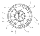
- FIG. 1 shows a pointer instrument 1 with an annular indicating surface 2 , for use in a motor vehicle.
- a display 3 is arranged as a central indicating unit, such that the indicating surface 2 concentrically surrounds the display 3 .
- a first, centrally supported pointer 4 is arranged for visible pivoting across the indicating surface 2 .
- the display 3 is arranged in front of the first pointer 4 from the viewpoint of the observer.
- a second pointer 5 is also arranged centrally behind the display 3 .
- the pointer tip 14 of the second pointer 5 is designed, analogously to the first pointer, for visibly pivoting across the indicating surface 2 .
- the indicating surface 2 has two scales 6 , 7 .
- the first scale 6 is from “0” to “25” and extends through 270° of the indicating surface 2 .
- the first pointer 4 is arranged such that it is pivotable across the area from “0” to “25”.
- the second scale 7 is from “H” to “L” and extends through almost 90° of the indicating surface 2 .
- the second pointer 5 is designed such that it is pivotable across this area.
- the indicating surface 2 is thus utilized across its entire extent for the presentation of information, since both pointers 4 , 5 together are pivotable through an angle range of 360°.
- FIG. 2 shows the pointer instrument 1 with the circular indicating surface 2 without display 3 . Only the fastening column 8 , with which the display is supported on a carrier of the indicating instrument 1 , is shown.
- the first pointer 4 is rectilinear and is mounted rotatably with its pointer bushing 10 at the center.
- the second pointer 5 has a pointer bushing 11 arranged inside the pointer bushing 10 of the first pointer 4 .
- a web 12 extends radially outward from the pointer bushing 11 as far as a ring segment 13 , which extends through 360°.
- a pointer tip 14 is secured on that side of the ring segment 13 lying opposite the web 12 .
- the center of gravity of the pointer 5 lies in the area of the pointer bushing 11 .
- two further webs 15 , 16 are arranged with respect to both sides of the first web 12 , symmetrically with respect to the web 12 .
- the two webs 15 , 16 form, with the ring segment 13 , a recess 17 , wherein the ring segment 13 and the two webs 15 , 16 are designed such that, when the second pointer 5 pivots across the second scale 7 , the fastening column 8 of the display is not touched.
- the first pointer 4 is likewise pivoted clockwise, such that an angle range of 360° of the indicating surface 2 is covered by the pointers in this configuration.
- FIGS. 3 a - e show the two pointers 4 , 5 and the fastening column 8 .
- the first pointer 4 is between “5” and “10” on the indicating surface 2
- the second pointer 5 is at “H”.
- the second pointer 5 consists of the pointer bushing 11 with the first web 12 , which in turn is connected to the ring segment 13 and to the pointer tip 14 secured thereon.
- the pointer 5 in FIG. 3 a corresponds to the pointer 5 in FIG. 2 .
- the pointer 5 in FIG. 3 b has only one web 12 .
- a pointer with a particularly simple structure of this kind has sufficient stability, for example through a suitable geometric configuration in terms of thickness and cross section or through the choice of material, preferably metal.
- the recess 17 has its greatest extent in this embodiment, permitting a range of pivoting of the second pointer 5 of almost 270° depending on the size of the fastening column 8 . In this way, the scale assigned to the second pointer 5 can be formed across a much greater angle range, which improves readability and/or permits a finer graduation of the scale.
- the ring segment 13 extends through an angle range of 180°.
- the two ends of the ring segment 13 are connected to the pointer bushing 11 by a respective web 12 , 15 .
- the pointer tip 14 is secured on the ring segment 13 at a 90° offset from the web 12 .
- the recess 17 is surrounded by the ring segment 13 and by the webs 12 , 15 .
- the ring segment 13 in FIG. 3 d extends through 90° and, at one end, is connected to the pointer bushing 11 by the web 12 .
- the pointer tip 14 is secured on the other end of the ring segment 13 .
- Web 12 and ring segment 13 thus form an open recess 17 .
- the open recess 17 thus allows the pointer 5 to pivot across an angle range greater than the angle range of the ring segment 13 .
- the pointer 5 in FIG. 3 e is a modification after FIG. 3 c , the webs 12 , 15 being curved outward. As a result of the curvature, the recess 17 is enlarged, which permits a greater range of pivoting of the pointer 5 .
- FIG. 4 shows the rear of the indicating surface 2 , the display 3 with its fastening column 8 , and the pointers 4 , 5 arranged in front of display 3 .
- the fastening column 8 is guided through the recess 17 of the pointer 5 .
- the recess 17 is formed by the webs 15 , 16 and the ring segment 13 .
- the pointer tip 14 is connected directly to the ring segment 13 . In this area, the pointer tip 14 has a coupling-in surface 18 for light.
- a coupling-out surface 19 of a light-guiding element 20 is arranged opposite the coupling-in surface 18 .
- the light-guiding element 20 extends with its coupling-out surface 19 along the trajectory of the coupling-in surface 18 of the pointer tip 14 .
- the light-guiding element 20 moreover has a coupling-in surface 21 for light from at least one light source 40 , such that the light from the light source can be guided by the light-guiding element 20 into the pointer tip 14 in order to illuminate the latter.
Landscapes
- Engineering & Computer Science (AREA)
- Chemical & Material Sciences (AREA)
- Combustion & Propulsion (AREA)
- Transportation (AREA)
- Mechanical Engineering (AREA)
- Physics & Mathematics (AREA)
- General Physics & Mathematics (AREA)
- Details Of Measuring Devices (AREA)
- Instrument Panels (AREA)
Applications Claiming Priority (7)
| Application Number | Priority Date | Filing Date | Title |
|---|---|---|---|
| DE102013220510.4 | 2013-10-11 | ||
| DE102013220510 | 2013-10-11 | ||
| DE102013220510 | 2013-10-11 | ||
| DE102014200367 | 2014-01-10 | ||
| DE201410200367 DE102014200367A1 (de) | 2013-10-11 | 2014-01-10 | Zeigerinstrument |
| DE102014200367.9 | 2014-10-01 | ||
| PCT/EP2014/071803 WO2015052327A1 (de) | 2013-10-11 | 2014-10-10 | Zeigerinstrument mit doppel-zeiger und excentrierter befestigungssäule |
Publications (2)
| Publication Number | Publication Date |
|---|---|
| US20160257200A1 US20160257200A1 (en) | 2016-09-08 |
| US9975430B2 true US9975430B2 (en) | 2018-05-22 |
Family
ID=52738196
Family Applications (1)
| Application Number | Title | Priority Date | Filing Date |
|---|---|---|---|
| US15/028,673 Active 2035-05-03 US9975430B2 (en) | 2013-10-11 | 2014-10-10 | Pointer instrument having a double pointer and an eccentrically arranged fastening column |
Country Status (5)
| Country | Link |
|---|---|
| US (1) | US9975430B2 (de) |
| EP (1) | EP3055653B1 (de) |
| JP (1) | JP6147425B2 (de) |
| DE (1) | DE102014200367A1 (de) |
| WO (1) | WO2015052327A1 (de) |
Citations (16)
| Publication number | Priority date | Publication date | Assignee | Title |
|---|---|---|---|---|
| DE207023C (de) | 1908-06-18 | 1909-02-17 | ||
| US3364748A (en) * | 1965-03-15 | 1968-01-23 | Honeywell Inc | Altitude indicating apparatus |
| US3997777A (en) * | 1975-12-18 | 1976-12-14 | Weston Instruments, Inc. | Indicator with hub lighting system and 360° concentric pointers |
| JPS5627611A (en) * | 1979-08-13 | 1981-03-18 | Miwa Denki Kk | Measuring instrument with fingers |
| DE19601270A1 (de) | 1996-01-16 | 1997-07-17 | Vdo Schindling | Für ein Kraftfahrzeug bestimmtes Zeigerinstrument |
| FR2850163A1 (fr) | 2003-01-22 | 2004-07-23 | Siemens Ag | Instrument a aiguille avec aiguille double |
| JP2004219210A (ja) | 2003-01-14 | 2004-08-05 | Yazaki Corp | 車両用表示装置 |
| DE102004052893A1 (de) * | 2004-11-02 | 2006-05-04 | Volkswagen Ag | Zeigerinstrument |
| DE60114129T2 (de) | 2000-07-31 | 2006-06-29 | Nippon Seiki Co. Ltd., Nagaoka | Beleuchtungsvorrichtung |
| US20070157869A1 (en) | 2006-01-11 | 2007-07-12 | Siemens Vdo Automotive Corporation | Instrument cluster display |
| EP1880890A1 (de) | 2006-07-20 | 2008-01-23 | Robert Bosch Gmbh | Anzeigevorrichtung |
| US20080202408A1 (en) | 2007-02-23 | 2008-08-28 | Continental Automotive Systems Us, Inc. | Illuminated instrument cluster |
| GB2470202A (en) | 2009-05-13 | 2010-11-17 | Visteon Global Tech Inc | Pointer display |
| DE102010001050A1 (de) * | 2010-01-20 | 2011-07-21 | Ford Global Technologies, LLC, Mich. | Skaleninstrument |
| US20120206251A1 (en) | 2011-02-16 | 2012-08-16 | Birman Vyacheslav B | Tell tale over cluster light guide |
| US9182254B2 (en) * | 2010-04-29 | 2015-11-10 | Sylvain Denise | Indicating device |
-
2014
- 2014-01-10 DE DE201410200367 patent/DE102014200367A1/de not_active Ceased
- 2014-10-10 JP JP2016521950A patent/JP6147425B2/ja not_active Expired - Fee Related
- 2014-10-10 US US15/028,673 patent/US9975430B2/en active Active
- 2014-10-10 WO PCT/EP2014/071803 patent/WO2015052327A1/de not_active Ceased
- 2014-10-10 EP EP14783830.4A patent/EP3055653B1/de active Active
Patent Citations (17)
| Publication number | Priority date | Publication date | Assignee | Title |
|---|---|---|---|---|
| DE207023C (de) | 1908-06-18 | 1909-02-17 | ||
| US3364748A (en) * | 1965-03-15 | 1968-01-23 | Honeywell Inc | Altitude indicating apparatus |
| US3997777A (en) * | 1975-12-18 | 1976-12-14 | Weston Instruments, Inc. | Indicator with hub lighting system and 360° concentric pointers |
| JPS5627611A (en) * | 1979-08-13 | 1981-03-18 | Miwa Denki Kk | Measuring instrument with fingers |
| DE19601270A1 (de) | 1996-01-16 | 1997-07-17 | Vdo Schindling | Für ein Kraftfahrzeug bestimmtes Zeigerinstrument |
| DE60114129T2 (de) | 2000-07-31 | 2006-06-29 | Nippon Seiki Co. Ltd., Nagaoka | Beleuchtungsvorrichtung |
| JP2004219210A (ja) | 2003-01-14 | 2004-08-05 | Yazaki Corp | 車両用表示装置 |
| FR2850163A1 (fr) | 2003-01-22 | 2004-07-23 | Siemens Ag | Instrument a aiguille avec aiguille double |
| DE10302386A1 (de) | 2003-01-22 | 2004-08-19 | Siemens Ag | Zeigerinstrument mit Doppelzeiger |
| DE102004052893A1 (de) * | 2004-11-02 | 2006-05-04 | Volkswagen Ag | Zeigerinstrument |
| US20070157869A1 (en) | 2006-01-11 | 2007-07-12 | Siemens Vdo Automotive Corporation | Instrument cluster display |
| EP1880890A1 (de) | 2006-07-20 | 2008-01-23 | Robert Bosch Gmbh | Anzeigevorrichtung |
| US20080202408A1 (en) | 2007-02-23 | 2008-08-28 | Continental Automotive Systems Us, Inc. | Illuminated instrument cluster |
| GB2470202A (en) | 2009-05-13 | 2010-11-17 | Visteon Global Tech Inc | Pointer display |
| DE102010001050A1 (de) * | 2010-01-20 | 2011-07-21 | Ford Global Technologies, LLC, Mich. | Skaleninstrument |
| US9182254B2 (en) * | 2010-04-29 | 2015-11-10 | Sylvain Denise | Indicating device |
| US20120206251A1 (en) | 2011-02-16 | 2012-08-16 | Birman Vyacheslav B | Tell tale over cluster light guide |
Also Published As
| Publication number | Publication date |
|---|---|
| JP6147425B2 (ja) | 2017-06-14 |
| JP2016535251A (ja) | 2016-11-10 |
| WO2015052327A1 (de) | 2015-04-16 |
| DE102014200367A1 (de) | 2015-04-16 |
| US20160257200A1 (en) | 2016-09-08 |
| EP3055653A1 (de) | 2016-08-17 |
| EP3055653B1 (de) | 2019-06-12 |
Similar Documents
| Publication | Publication Date | Title |
|---|---|---|
| CN102835005B (zh) | 仪表单元 | |
| US6817310B2 (en) | Dial plate, its manufacturing method, meter using the same, in-vehicle status indicator and meter using the same | |
| CN102414541A (zh) | 仪表照明装置 | |
| US20130055837A1 (en) | Instrumental unit | |
| EP2348291A2 (de) | Zeigerstruktur eines Instrumentenclusters | |
| EP2402720A1 (de) | Messgerät mit nadelanzeige | |
| CN100460828C (zh) | 车用显示设备 | |
| US9975430B2 (en) | Pointer instrument having a double pointer and an eccentrically arranged fastening column | |
| ATE391286T1 (de) | Scheibenzeiger | |
| CN105980192B (zh) | 用于机动车辆的显示装置 | |
| JP2009512855A (ja) | 表示変更式ダッシュパネル | |
| KR101784732B1 (ko) | 히든 포인터를 위한 자가 발광 디스플레이를 가지고 있는 얇은 게이지 | |
| WO2009104559A1 (ja) | 車両用表示装置 | |
| JP2013088351A (ja) | メータ装置 | |
| WO2007051097A3 (en) | Analog image information display | |
| CN102159923B (zh) | 包括用于超照明刻度的一部分的装置的背光刻度计 | |
| JP6717279B2 (ja) | 車両用指針計器 | |
| CN107068203B (zh) | 用于显示交通工具的至少一个状态参量的显示设备 | |
| JP6400185B2 (ja) | 車両用表示装置 | |
| EP3121053A2 (de) | Cluster-beleuchtung durch piezoelektrisches material | |
| CN203318178U (zh) | 汽车仪表悬浮式渐变光晕结构 | |
| JP6026135B2 (ja) | 指針ユニット | |
| JP2014038102A (ja) | インスツルメントクラスタゲージのためのレーダ効果装置及び方法 | |
| JP5050660B2 (ja) | 指針式計器 | |
| JP5496698B2 (ja) | 車両用指針計器 |
Legal Events
| Date | Code | Title | Description |
|---|---|---|---|
| STCF | Information on status: patent grant |
Free format text: PATENTED CASE |
|
| MAFP | Maintenance fee payment |
Free format text: PAYMENT OF MAINTENANCE FEE, 4TH YEAR, LARGE ENTITY (ORIGINAL EVENT CODE: M1551); ENTITY STATUS OF PATENT OWNER: LARGE ENTITY Year of fee payment: 4 |
|
| AS | Assignment |
Owner name: CONTINENTAL AUTOMOTIVE TECHNOLOGIES GMBH, GERMANY Free format text: ASSIGNMENT OF ASSIGNORS INTEREST;ASSIGNOR:CONTINENTAL AUTOMOTIVE GMBH;REEL/FRAME:070441/0899 Effective date: 20241211 |
|
| MAFP | Maintenance fee payment |
Free format text: PAYMENT OF MAINTENANCE FEE, 8TH YEAR, LARGE ENTITY (ORIGINAL EVENT CODE: M1552); ENTITY STATUS OF PATENT OWNER: LARGE ENTITY Year of fee payment: 8 |